DFR552 - Screwdriver MAKITA - Free user manual and instructions
Find the device manual for free DFR552 MAKITA in PDF.

User questions about DFR552 MAKITA
0 question about this device. Answer the ones you know or ask your own.
Ask a new question about this device
Download the instructions for your Screwdriver in PDF format for free! Find your manual DFR552 - MAKITA and take your electronic device back in hand. On this page are published all the documents necessary for the use of your device. DFR552 by MAKITA.
USER MANUAL DFR552 MAKITA
natural_image
Technical line drawings of two different types of firearms (no text or symbols present)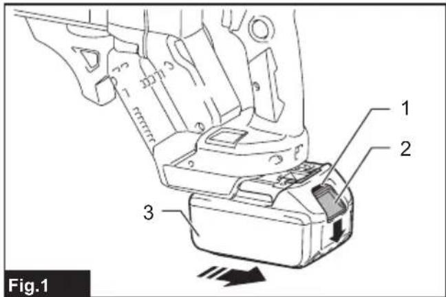
text_image
Fig.1 1 2 3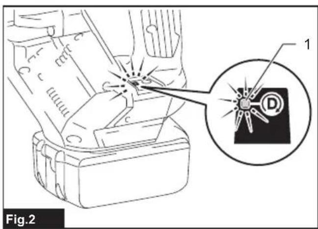
text_image
Fig.2 1 D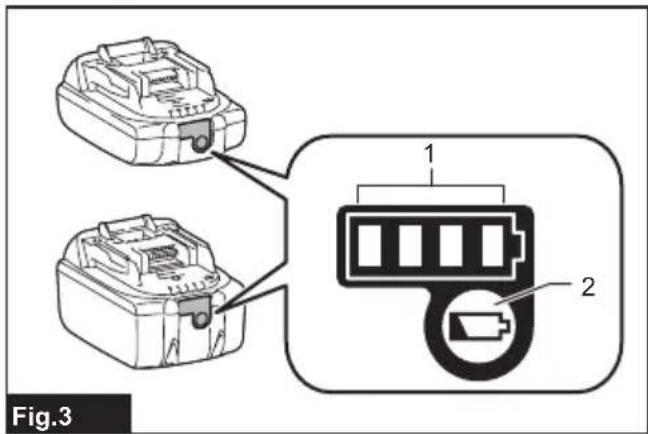
text_image
Fig.3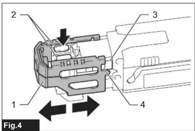
text_image
2 3 1 4 Fig.4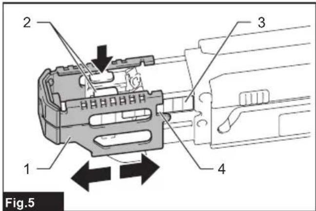
text_image
2 3 1 4 Fig.5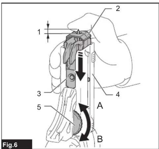
text_image
1 2 3 4 5 A B Fig.6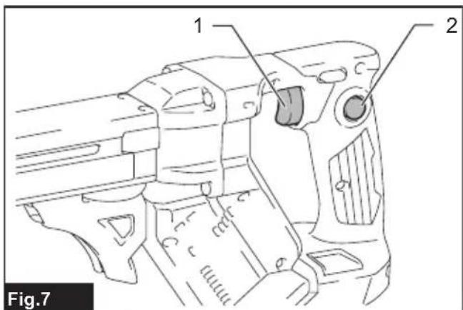
text_image
1 2 Fig.7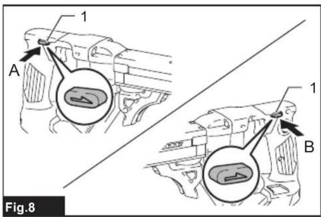
text_image
1 A 1 B Fig.8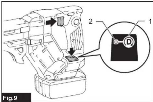
text_image
Fig.9 2 1 D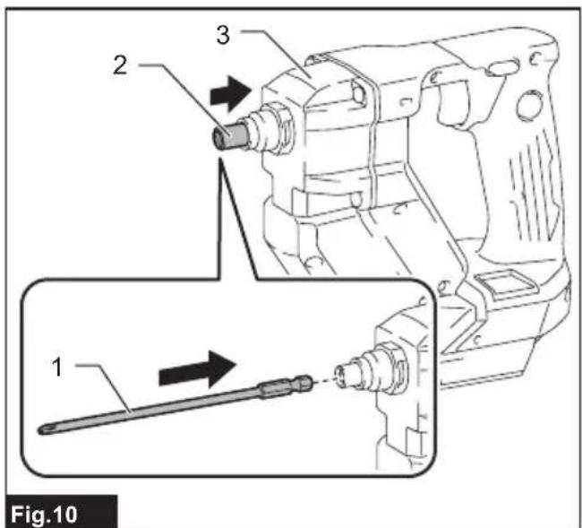
text_image
1 2 3 Fig.10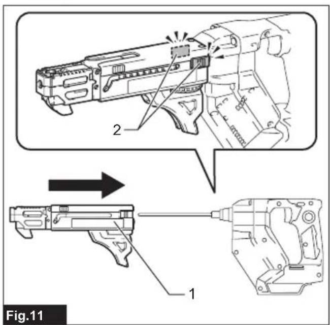
text_image
Fig.11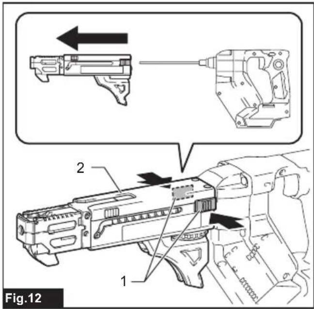
text_image
Fig.12 1 2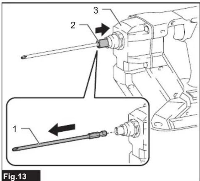
text_image
Fig.13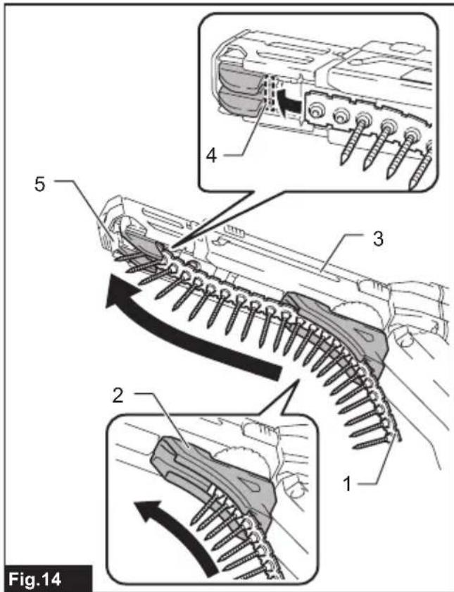
text_image
Fig.14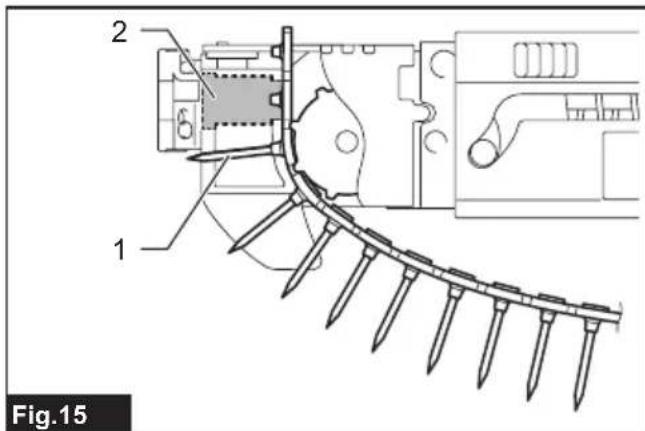
text_image
2 6 1 Fig.15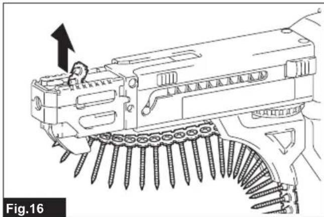
natural_image
Technical line drawing of a mechanical assembly with screws and a bracket, no visible text or symbols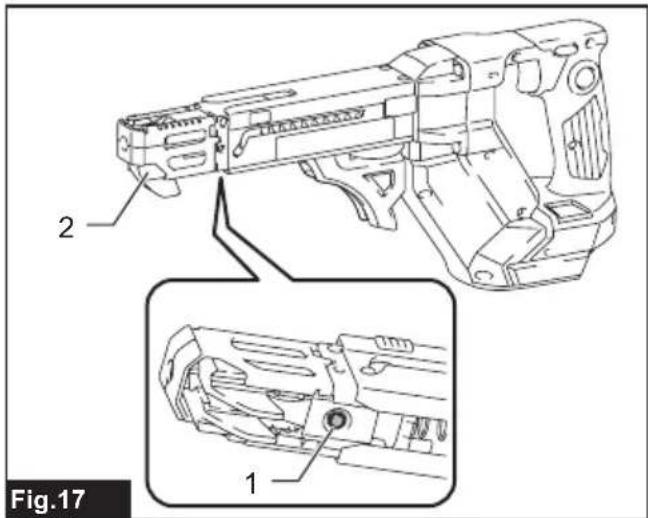
text_image
2 1 Fig.17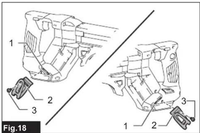
text_image
Fig.18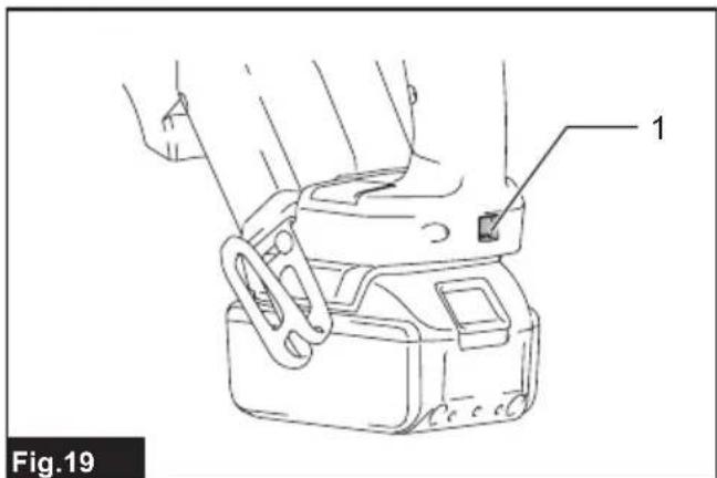
text_image
1 Fig.19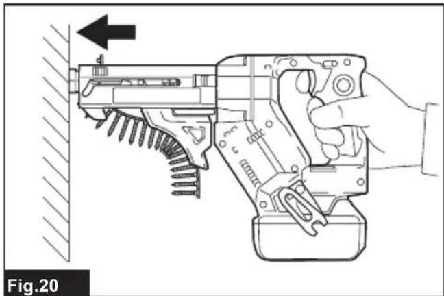
natural_image
Line drawing of a hand using a disassembled gun to handle a wall, showing mechanical components and tool path (no text or symbols)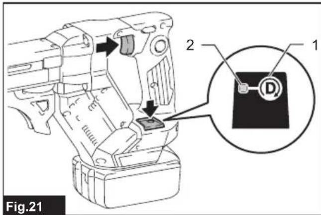
text_image
Fig.21 2 1 D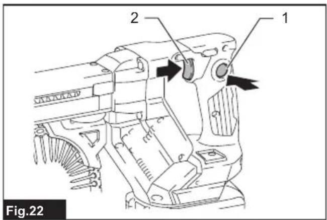
text_image
Fig.22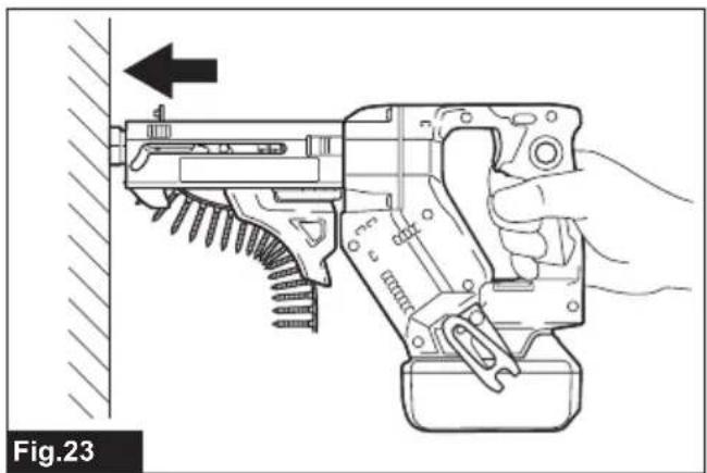
natural_image
Line drawing of a hand using a firearm to adjust a tool, showing mechanical components and a directional arrow (no text or symbols)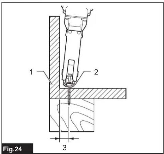
text_image
Fig.24 1 2 3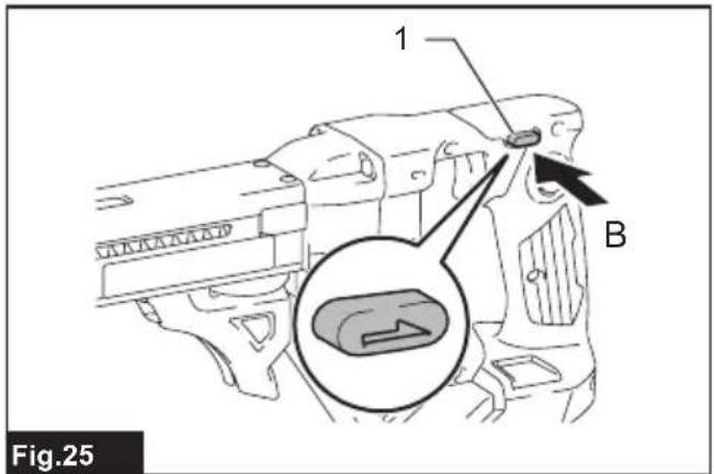
text_image
1 B Fig.25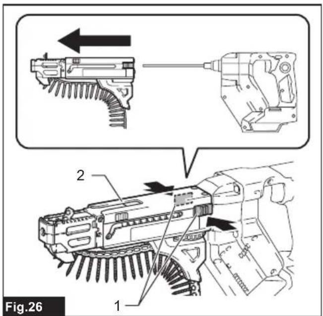
text_image
Fig.26 1 2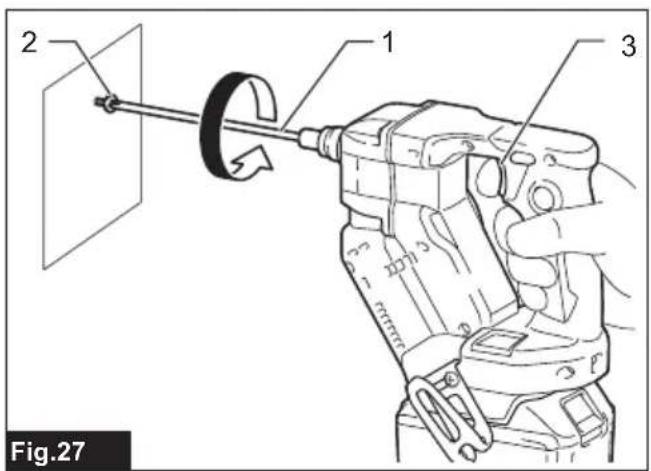
text_image
2 1 3 Fig.27SPECIFICATIONS
| Model: DFR452 DFR453 DFR551 DFR552 | ||||
| Screw strip | 3.5 mm × 20 mm - 4.2 mm × 41 mm | 3.5 mm × 25 mm - 4.2 mm × 55 mm | ||
| No load speed 0 - 6,000 min | ^-1 | 0 - 4,500 min^-1 | 0 - 6,000 min^-1 | 0 - 4,500 min^-1 |
| Overall length 360 mm 396 mm | ||||
| Rated voltage D.C. 18 V | ||||
| Net weight 1.9 - 2.2 kg | ||||
- Due to our continuing program of research and development, the specifications herein are subject to change without notice.
• Specifications may differ from country to country. - The weight may differ depending on the attachment(s), including the battery cartridge. The lightest and heaviest combinations, according to EPTA-Procedure 01/2014, are shown in the table.
Applicable battery cartridge and charger
| Battery cartridge BL1815N / BL1820B / BL1830B / BL1840B / BL1850B / BL1860B |
| Charger DC18RC / DC18RD / DC18RE / DC18SD / DC18SE / DC18SF /DC18SH / DC18WC |
- Some of the battery cartridges and chargers listed above may not be available depending on your region of residence.
WARNING: Only use the battery cartridges and chargers listed above. Use of any other battery cartridges and chargers may cause injury and/or fire.
Intended use
The tool is intended for screw driving in wood, metal and plastic.
Noise
The typical A-weighted noise level determined according to EN62841-2-2:
| Model Sound pressure | level (LpA) : (dB(A)) | Uncertainty (K) : (dB(A)) | |
| DFR452 | 78 | 3 | |
| DFR453 | 79 | 3 | |
| DFR551 | 77 | 3 | |
| DFR552 | 78 | 3 | |
The noise level under working may exceed 80 dB (A).
NOTE: The declared noise emission value(s) has been measured in accordance with a standard test method and may be used for comparing one tool with another.
NOTE: The declared noise emission value(s) may also be used in a preliminary assessment of exposure.
WARNING: Wear ear protection.
⚠ WARNING: The noise emission during actual use of the power tool can differ from the declared value(s) depending on the ways in which the tool is used especially what kind of workpiece is processed.
WARNING: Be sure to identify safety measures to protect the operator that are based on an estimation of exposure in the actual conditions of use (taking account of all parts of the operating cycle such as the times when the tool is switched off and when it is running idle in addition to the trigger time).
Vibration
The vibration total value (tri-axial vector sum) determined according to EN62841-2-2:
Work mode: screwdriving without impact
| Model Vibration emis-sion (ah): (m/s2) | Uncertainty (K): (m/s2) | |
| DFR452 2.5 m/s | 2or less | 1.5 m/s2 |
| DFR453 | ||
| DFR551 | ||
| DFR552 | ||
NOTE: The declared vibration total value(s) has been measured in accordance with a standard test method and may be used for comparing one tool with another.
NOTE: The declared vibration total value(s) may also be used in a preliminary assessment of exposure.
⚠ WARNING: The vibration emission during actual use of the power tool can differ from the declared value(s) depending on the ways in which the tool is used especially what kind of workpiece is processed.
⚠ WARNING: Be sure to identify safety measures to protect the operator that are based on an estimation of exposure in the actual conditions of use (taking account of all parts of the operating cycle such as the times when the tool is switched off and when it is running idle in addition to the trigger time).
Declarations of Conformity
For European countries only
The Declarations of conformity are included in Annex A to this instruction manual.
SAFETY WARNINGS
General power tool safety warnings
⚠ WARNING Read all safety warnings, instructions, illustrations and specifications provided with this power tool. Failure to follow all instructions listed below may result in electric shock, fire and/or serious injury.
Save all warnings and instructions for future reference.
The term "power tool" in the warnings refers to your mains-operated (corded) power tool or battery-operated (cordless) power tool.
Cordless screwdriver safety warnings
- Hold the power tool by insulated gripping surfaces, when performing an operation where the fastener may contact hidden wiring. Fasteners contacting a "live" wire may make exposed metal parts of the power tool "live" and could give the operator an electric shock.
- Always be sure you have a firm footing. Be sure no one is below when using the tool in high locations.
- Hold the tool firmly.
- Keep hands away from rotating parts.
- Do not touch the bit or the workpiece immediately after operation; they may be extremely hot and could burn your skin.
- Always secure workpiece in a vise or similar hold-down device.
- Make sure there are no electrical cables, water pipes, gas pipes etc. that could cause a hazard if damaged by use of the tool.
SAVE THESE INSTRUCTIONS.
⚠ WARNING: DO NOT let comfort or familiarity with product (gained from repeated use) replace strict adherence to safety rules for the subject product.
MISUSE or failure to follow the safety rules stated in this instruction manual may cause serious personal injury.
Important safety instructions for battery cartridge
- Before using battery cartridge, read all instructions and cautionary markings on (1) battery charger, (2) battery, and (3) product using battery.
- Do not disassemble or tamper with the battery cartridge. It may result in a fire, excessive heat, or explosion.
- If operating time has become excessively shorter, stop operating immediately. It may result in a risk of overheating, possible burns and even an explosion.
-
If electrolyte gets into your eyes, rinse them out with clear water and seek medical attention right away. It may result in loss of your eyesight.
-
Do not short the battery cartridge:
(1) Do not touch the terminals with any conductive material.
(2) Avoid storing battery cartridge in a container with other metal objects such as nails, coins, etc.
(3) Do not expose battery cartridge to water or rain.
A battery short can cause a large current flow, overheating, possible burns and even a breakdown.
-
Do not store and use the tool and battery cartridge in locations where the temperature may reach or exceed 50 °C (122 °F).
-
Do not incinerate the battery cartridge even if it is severely damaged or is completely worn out. The battery cartridge can explode in a fire.
-
Do not nail, cut, crush, throw, drop the battery cartridge, or hit against a hard object to the battery cartridge. Such conduct may result in a fire, excessive heat, or explosion.
-
Do not use a damaged battery.
-
The contained lithium-ion batteries are subject to the Dangerous Goods Legislation requirements.
For commercial transports e.g. by third parties, forwarding agents, special requirement on packaging and labeling must be observed.
For preparation of the item being shipped, consulting an expert for hazardous material is required. Please also observe possibly more detailed national regulations.
Tape or mask off open contacts and pack up the battery in such a manner that it cannot move around in the packaging.
- When disposing the battery cartridge, remove it from the tool and dispose of it in a safe place. Follow your local regulations relating to disposal of battery.
- Use the batteries only with the products specified by Makita. Installing the batteries to non-compliant products may result in a fire, excessive heat, explosion, or leak of electrolyte.
- If the tool is not used for a long period of time, the battery must be removed from the tool.
- During and after use, the battery cartridge may take on heat which can cause burns or low temperature burns. Pay attention to the handling of hot battery cartridges.
- Do not touch the terminal of the tool immediately after use as it may get hot enough to cause burns.
- Do not allow chips, dust, or soil stuck into the terminals, holes, and grooves of the battery cartridge. It may cause heating, catching fire, burst and malfunction of the tool or battery cartridge, resulting in burns or personal injury.
- Unless the tool supports the use near high-voltage electrical power lines, do not use the battery cartridge near high-voltage electrical power lines. It may result in a malfunction or breakdown of the tool or battery cartridge.
- Keep the battery away from children.
SAVE THESE INSTRUCTIONS.
CAUTION: Only use genuine Makita batteries.
Use of non-genuine Makita batteries, or batteries that have been altered, may result in the battery bursting causing fires, personal injury and damage. It will also void the Makita warranty for the Makita tool and charger.
Tips for maintaining maximum battery life
- Charge the battery cartridge before completely discharged. Always stop tool operation and charge the battery cartridge when you notice less tool power.
- Never recharge a fully charged battery cartridge. Overcharging shortens the battery service life.
- Charge the battery cartridge with room temperature at 10 °C - 40 °C (50 °F - 104 °F). Let a hot battery cartridge cool down before charging it.
- When not using the battery cartridge, remove it from the tool or the charger.
- Charge the battery cartridge if you do not use it for a long period (more than six months).
FUNCTIONAL DESCRIPTION
CAUTION: Always be sure that the tool is switched off and the battery cartridge is removed before adjusting or checking function on the tool.
Installing or removing battery cartridge
CAUTION: Always switch off the tool before installing or removing of the battery cartridge.
CAUTION: Hold the tool and the battery cartridge firmly when installing or removing battery cartridge. Failure to hold the tool and the battery cartridge firmly may cause them to slip off your hands and result in damage to the tool and battery cartridge and a personal injury.
To install the battery cartridge, align the tongue on the battery cartridge with the groove in the housing and slip it into place. Insert it all the way until it locks in place with a little click. If you can see the red indicator as shown in the figure, it is not locked completely.
To remove the battery cartridge, slide it from the tool while sliding the button on the front of the cartridge.
▶ Fig.1: 1. Red indicator 2. Button 3. Battery cartridge
CAUTION: Always install the battery cartridge fully until the red indicator cannot be seen. If not, it may accidentally fall out of the tool, causing injury to you or someone around you.
⚠️ CAUTION: Do not install the battery cartridge forcibly. If the cartridge does not slide in easily, it is not being inserted correctly.
Tool / battery protection system
The tool is equipped with a tool/battery protection system. This system automatically cuts off power to the motor to extend tool and battery life. The tool will automatically stop during operation if the tool or battery is placed under one of the following conditions:
Overload protection
When the tool/battery is operated in a manner that causes it to draw an abnormally high current, the tool stops automatically. In this situation, turn the tool off and stop the application that caused the tool to become overloaded. Then turn the tool on to restart.
Overheat protection
When the tool/battery is overheated, the tool stops automatically. In this situation, let the tool/battery cool before turning the tool on again.
Overdischarge protection
When the battery capacity is not enough, the tool stops automatically. In this case, remove the battery from the tool and charge the battery.
Protections against other causes
Protection system is also designed for other causes that could damage the tool and allows the tool to stop automatically. Take all the following steps to clear the causes, when the tool has been brought to a temporary halt or stop in operation.
- Turn the tool off, and then turn it on again to restart.
- Charge the battery(ies) or replace it/them with recharged battery(ies).
- Let the tool and battery(ies) cool down.
If no improvement can be found by restoring protection system, then contact your local Makita Service Center.
Alert indicator
The indicator lamp on the push drive mode selector raises an alert with flashing red lights when the tool works in the following operating conditions.
▶ Fig.2: 1. Indicator lamp
| Lamp status Causes Remedies | ||
| Fast flashing (approx. one-third second intervals) | Battery getting low | Charge the battery at your earliest opportunity. |
| Delayed flashing (approx. a second intervals) | Overheated | Let the tool cool down before turning it on again. |
NOTE: An over-discharge alert may appear depending on the battery status and operational conditions.
Indicating the remaining battery capacity
Only for battery cartridges with the indicator
Press the check button on the battery cartridge to indicate the remaining battery capacity. The indicator lamps light up for a few seconds.
▶ Fig.3: 1. Indicator lamps 2. Check button
| Indicator lamps Remaining | capacity | ||
| Lighted Off | Blinking | ||
| ### | 75% to 100% | ||
| ### | 50% to 75% | ||
| ### | 25% to 50% | ||
| ### | 0% to 25% | ||
| ### | Charge the battery. | ||
| ### | The battery may have malfunctioned. | ||
 | |||
NOTE: Depending on the conditions of use and the ambient temperature, the indication may differ slightly from the actual capacity.
NOTE: The first (far left) indicator lamp will blink when the battery protection system works.
Setting for desired screw lengths
For model DFR452 / DFR453
The tool provides 4 positive-lock screw length settings. Slide the stopper base out and in while depressing the levers on the top surface of the stopper base so the number for desired screw length (indicated on the label) appears in the reading window. See the following table for details on the numbers allocated to your desired screw lengths.
▶ Fig.4: 1. Stopper base 2. Levers 3. Label 4. Reading window
| Numbers indicated on the label | Screw length ranges |
| 20 20 mm (13/16") | |
| 25 25 mm - 28 | mm (1" - 1-1/8") |
| 32 28 mm - 35 | mm (1-1/8" - 1-3/8") |
| 41 35 mm - 41 | mm (1-3/8" - 1-5/8") |
For model DFR551 / DFR552
The tool provides 7 positive-lock screw length settings. Slide the stopper base out and in while depressing the levers on the top surface of the stopper base so the number for desired screw length (indicated on the label) appears in the reading window. See the following table for details on the numbers allocated to your desired screw lengths.
▶ Fig.5: 1. Stopper base 2. Levers 3. Label 4. Reading window
| Numbers indicated on the label | Screw length ranges |
| 25 25 mm (1") | |
| 30 25 mm - 30 | mm (1" - 1-3/16") |
| 35 30 mm - 35 | mm (1-3/16" - 1-3/8") |
| 40 35 mm - 40 | mm (1-3/8" - 1-9/16") |
| 45 40 mm - 45 | mm (1-9/16" - 1-3/4") |
| 50 45 mm - 50 | mm (1-3/4" - 2") |
| 55 50 mm - 55 | mm (2" - 2-3/16") |
Adjusting driving depths
Press the front face of the stopper base and hold the feeder box down into the casing as far as it will go.
While keeping it in that position, turn the adjusting dial so that the driver bit tip comes out approximately 6 mm from the front face of the stopper base.
Drive a trial screw. If the screw head stands above the workpiece surface, turn the adjusting dial in the A direction; if the screw head sits below the surface, turn the adjusting dial in the B direction.
▶ Fig.6: 1. Approx. 6 mm 2. Stopper base 3. Feeder box 4. Casing 5. Adjusting dial
Switch action
WARNING: Before installing the battery cartridge into the tool, always check to see that the switch trigger actuates properly and returns to the "OFF" position when released.
To start the tool, pull the switch trigger. Tool speed is increased by increasing pressure on the switch trigger. Release the switch trigger to stop.
For continuous operation, pull the switch trigger, push in the lock button and then release the trigger. To stop the tool from the locked position, pull the switch trigger fully, and then release it.
▶ Fig.7: 1. Switch trigger 2. Lock button
Reversing switch action
A CAUTION: Always check the direction of rotation before operation.
⚠️CAUTION: Use the reversing switch only after the tool comes to a complete stop. Changing the direction of rotation before the tool stops may damage the tool.
⚠CAUTION: When not operating the tool, always set the reversing switch lever to the neutral position.
This tool has a reversing switch to change the direction of rotation. Depress the reversing switch lever from the A side for clockwise rotation or from the B side for counterclockwise rotation.
When the reversing switch lever is in the neutral position, the switch trigger cannot be pulled.
▶ Fig.8: 1. Reversing switch lever
Push drive mode
In push drive mode, the driver bit only rotates by applying pressure onto the driving surface with the stopper base, allowing the tool to cut off power to the motor to save battery power at idle.
To select push drive mode, pull the switch trigger slightly, then release it and quickly press the mode select button. The indicator lamp on the push drive mode selector will then light up.
▶ Fig.9: 1. Mode select button 2. Indicator lamp
NOTE: Push drive mode will automatically be deactivated after eight hours with the switch trigger locked on and no further switch operation. To restart the tool, pull the switch trigger fully to release the lock button, and pull the trigger again.
Accidental re-start preventive function
Even if you install the battery cartridge while pulling the switch trigger, the tool does not start.
To start the tool, first release the switch trigger and then pull the switch trigger.
ASSEMBLY
CAUTION: Always be sure that the tool is switched off and the battery cartridge is removed before carrying out any work on the tool.
Installing and removing driver bit
CAUTION: Be careful not to touch the sharp edges of screws while reassembling the components and attachments.
CAUTION: Handle accessories and attachments with care. Always be sure to hold accessories and attachments body firmly when installing and removing. Otherwise the accessories and attachments may slip off from your hands and fall.
⚠️ CAUTION: Hold the casing when installing and removing attachments.
⚠️ CAUTION: Always switch off and remove the battery cartridge when changing the bit.
Installing driver bit
-
To install a driver bit, place it into the spindle hole as far as it will go while pushing and holding the spindle into the gear housing. Then release the spindle to secure the driver bit.
▶ Fig.10: 1. Driver bit 2. Spindle 3. Gear housing -
Push the casing into the gear housing while holding the body of the casing firmly until the release buttons on each side of the casing lock in place with a little click.
▶ Fig.11: 1. Casing 2. Release buttons
Removing driver bit
- Press and hold the release buttons on each side of the casing, and then pull the casing apart.
▶ Fig.12: 1. Release buttons 2. Casing - To remove the driver bit, pull it off while pushing and holding the spindle into the gear housing.
▶ Fig.13: 1. Driver bit 2. Spindle 3. Gear housing
Installing screw strip
⚠️ CAUTION: Always switch off and remove the battery cartridge when cutting the screw strip.
Insert a screw strip through the screw strip guide on the casing, and then insert it through the screw loading guide in the feeder box.
▶ Fig.14: 1. Screw strip 2. Screw strip guide 3. Casing 4. Screw loading guide 5. Feeder box
NOTICE: Make sure to set the first screw in the second row next to the driving position.
▶ Fig.15: 1. First screw 2. Driving position
Removing screw strip
⚠️CAUTION: Always remove the screw strip before removing the attachment.
To remove the screw strip, pull it upwards out of the feeder box.
▶ Fig.16
The screw strip can be pulled downwards out of the feeder box while pressing the reverse button on the feeder box.
▶ Fig.17: 1. Reverse button 2. Feeder box
Installing hook
WARNING: Use the hanging/mounting parts for their intended purposes only, e.g., hanging the tool on a tool belt between jobs or work intervals.
⚠ WARNING: Be careful not to overload the hook as too much force or irregular overburden may cause damages to the tool resulting in personal injury.
⚠️CAUTION: When installing the hook, always secure it with the screw firmly. If not, the hook may come off from the tool and result in the personal injury.
⚠️CAUTION: Make sure to hang the tool securely before releasing your hold. Insufficient or unbalanced hooking may cause falling off and you may be injured.
▶ Fig.18: 1. Groove 2. Hook 3. Screw
The hook is convenient for temporarily hanging the tool. This can be installed on either side of the tool. To install the hook, insert it into a groove in the tool housing on either side and then secure it with a screw. To remove, loosen the screw and then take it out.
Using hole
WARNING: Never use the hanging hole for unintended purpose, for instance, tethering the tool at high location. Bearing stress in a heavily loaded hole may cause damages to the hole, resulting in injuries to you or people around or below you.
Use the hanging hole at the bottom rear of the tool to hang the tool on a wall using a hanging cord or similar strings.
▶ Fig.19: 1. Hanging hole
OPERATION
Driving operation
NOTICE: Always check the driver bit carefully for wear before driving operations. Replace a worn driver bit or poor fastening may result.
NOTICE: Always hold the tool squarely against the driving surface. Holding it at an angle may damage the screw heads and cause wear on the driver bit. This may also lead to poor fastening.
NOTICE: Always keep the tool firmly against the driving surface until the driving is over. Failure to do so may cause insufficient fastening of screws.
NOTICE: Be careful not to drive a screw onto another screw already fastened.
NOTICE: Do not operate the tool without screws. It will damage the driving surface.
NOTICE: Do not apply oil or grease on the sliding surface of the feeder box.
Switch on the tool by pulling the switch trigger. Hold the tool squarely and firmly up against the driving surface. A screw will be automatically carried to the driving position and fastened.
▶ Fig.20
Driving operation in push drive mode
- Pull the switch trigger slightly and release it. Then quickly press the mode select button.
The indicator lamp on the push drive mode selector lights up, and push drive mode becomes activated.
▶ Fig.21: 1. Mode select button 2. Indicator lamp
- Depress the lock button while pulling the switch trigger, and then release the switch trigger.
▶ Fig.22: 1. Lock button 2. Switch trigger
NOTE: While selecting push drive mode and locking the trigger on, the motor does not rotate under no load to minimize power consumption.
- Hold the tool squarely against the driving surface and apply forward pressure to the tool.
The screw will be automatically carried to the driving position and driven at full speed.
▶ Fig.23
Driving in corner
CAUTION: Driving at a position closer than 15 mm to the wall or driving with the stopper base in contact with the wall may damage the screw heads and cause wear on the driver bit. This may also lead to poor fastening of screws and malfunction of the tool.
This tool can be used to drive at a position 15 mm away from the wall as shown in the figure.
▶ Fig.24: 1. Wall 2. Stopper base 3. 15 mm
Unfastening operation
⚠️CAUTION: Always check the direction of rotation before operation.
⚠️CAUTION: Use the reversing switch only after the tool comes to a complete stop. Changing the direction of rotation before the tool stops may damage the tool.
The tool allows you to change the direction of driver bit rotation with ease, either towards the right (clockwise) to tighten a screw or towards the left (counterclockwise) to loosen a screw.
- Depress the reversing switch lever from the B side for counterclockwise rotation.
▶ Fig.25: 1. Reversing switch lever -
Press and hold the release buttons on each side of the casing, and then pull the casing apart.
▶ Fig.26: 1. Release buttons 2. Casing -
Place the tip of the driver bit into the head of the screw to be loosened.
- Hold the tool firmly against the screw and squeeze the switch trigger to start.
▶ Fig.27: 1. Driver bit 2. Screw head 3. Switch trigger - Reset the casing back onto the gear housing until it locks in place after finishing operation.
MAINTENANCE
⚠️CAUTION: Always be sure that the tool is switched off and the battery cartridge is removed before attempting to perform inspection or maintenance.
NOTICE: Never use gasoline, benzine, thinner, alcohol or the like. Discoloration, deformation or cracks may result.
To maintain product SAFETY and RELIABILITY, repairs, any other maintenance or adjustment should be performed by Makita Authorized or Factory Service Centers, always using Makita replacement parts.
After use
Wipe off the tool using a dry cloth or cloth slightly moistened with soapy water at regular intervals.
OPTIONAL ACCESSORIES
CAUTION: These accessories or attachments are recommended for use with your Makita tool specified in this manual. The use of any other accessories or attachments might present a risk of injury to persons. Only use accessory or attachment for its stated purpose.
If you need any assistance for more details regarding these accessories, ask your local Makita Service Center.
- Drywall screw strip
- Phillips bit
- Square bit
- Pozidriv bit
- Casing
• Makita genuine battery and charger
NOTE: Some items in the list may be included in the tool package as standard accessories. They may differ from country to country.
SPÉCIFICATIONS
VEILIGHEIDSWAAR- SCHUWINGEN
▶ Fig.18: 1. Gleuf 2. Haak 3. Schroef
▶ Fig.27: 1. Schroefbit 2. Schroefkop
OPTIONELE ACCESSOIRES
▶ Fig.24: 1. Pared 2. Base de tope 3. 15 mm
▶ Fig.18: 1. Ranhura 2. Gancho 3. Parafuso