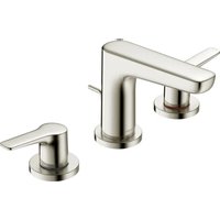
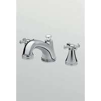
TLG03201U - Faucet TOTO - Free user manual and instructions
Find the device manual for free TLG03201U TOTO in PDF.


| Brand | TOTO |
| Model | TLG03201U |
| Product Type | Widespread faucet |
| Number of Handles | 2 |
| Mounting Type | 3-hole, widespread |
| Minimum Operating Pressure | 20 psi (138 kPa) dynamic |
| Maximum Operating Pressure | 80 psi (551 kPa) static |
| Ambient Temperature | 0 to 40 °C (32 to 104 °F) |
| Maximum Humidity | 90% RH |
| Maximum Flow Rate | 1.2 gallon/min (4.5 L/min) |
| Supply Connection | NPSM 1/2" |
| Material | Chrome-plated brass |
| Finish | Chrome |
| Drain Included | Yes |
| Included Parts | Faucet assembly, drain lift rod, 2 valve assemblies, 2 handle assemblies, aerator key, drain assembly, hex wrench (2 mm) |
| Warranty | 3 years for original purchaser |
| Care | Mild soap, warm water, soft cloth. Avoid abrasive cleaners, steel wool, harsh chemicals |
| Safety | Do not use below 0 °C (32 °F) |
| Supply | Cold and hot water |
| Installation Instructions Included | Yes |
Frequently Asked Questions - TLG03201U TOTO
User questions about TLG03201U TOTO
0 question about this device. Answer the ones you know or ask your own.
Ask a new question about this device
Download the instructions for your Faucet in PDF format for free! Find your manual TLG03201U - TOTO and take your electronic device back in hand. On this page are published all the documents necessary for the use of your device. TLG03201U by TOTO.
USER MANUAL TLG03201U TOTO
Installation and Owner's Manual
Wide Spread Lavatory Faucet
natural_image
Line drawing of a pair of bathroom fixtures (no text or symbols)GO TLG01201U
natural_image
Pure technical line drawing of a mechanical bracket or clamp (no text or symbols)GR TLG02201U
natural_image
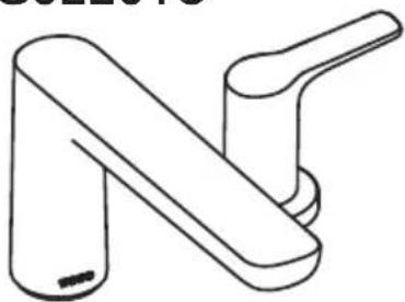
Line drawing of a double-ended faucet handle (no text or symbols)GS TLG03201U
| TABLE OF CONTENTS |
| Thanks for Choosing TOTO!......2 Tools You Will Need......3Warnings......2 Specifications......3Before Installation......2 Installation Procedure......4Care and Cleaning......2 Warranty......8Included Parts......3 Rough-In Dimensions......30 |
| THANK YOU FOR CHOOSING TOTO! |
| The mission of TOTO is to provide the world with healthy, hygienic and more comfortable lifestyles. We design every product with the balance of form and function as a guiding principle. Congratulations on your choice. |
| WARNINGS |
| For safe operation of the faucet, please observe the following:■ Operating Pressure:· Minimum Pressure......20 psi (138 kPa), dynamic· Maximum Pressure......80 psi (551 kPa), static■ Do not use the product at an ambient temperature below 32° F (0°C) |
| BEFORE INSTALLATION |
| ■ Observe all local plumbing codes.■ Before installing the faucet, be sure to thoroughly flush the supply pipes of dirt and debris.■ Make sure the water supply is shut off at the stop valve.■ Read these instructions carefully to ensure proper installation.■ TOTO reserves the right to update product design without notice. |
| CARE AND CLEANING |
| Your new faucet is designed for years of trouble-free performance. Keep it looking new by cleaning it periodically with mild soap, rinsing thoroughly with warm water and drying with a clean, soft cloth. Do not use abrasive cleaners, steel wool or harsh chemicals, as thes will dull the finish. Failure to follow these instructions may void your warranty |
INCLUDED PARTS
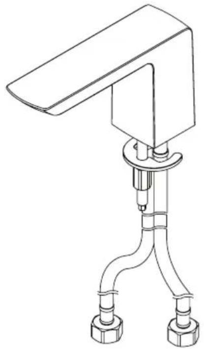
Check to make sure you have the following parts indicated below:
natural_image
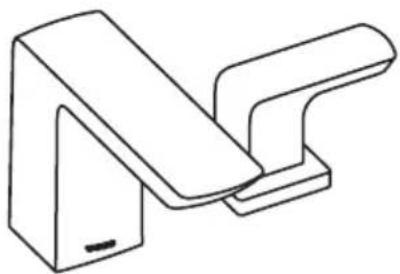
Technical line drawing of a mechanical device with two connectors and a central lever (no text or symbols)Spout Assembly
natural_image
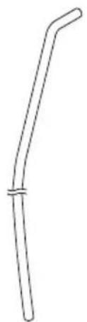
Simple line drawing of a bent tube or rod with a central bar (no text or symbols)Drain Lift Rod
natural_image
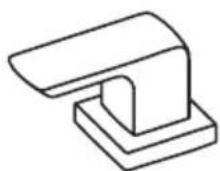
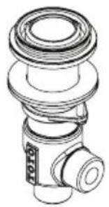
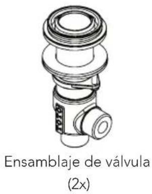
Technical line drawing of a mechanical component with no visible text or symbolsValve Assembly (2x)
natural_image
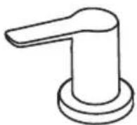
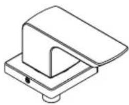
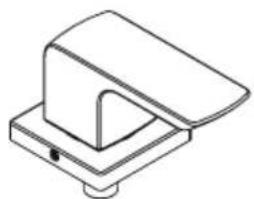
Simple line drawing of a mechanical component with a flanged top and base (no text or symbols)Handle Assembly (2x)
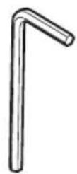
Hex Wrench (2 mm)

Aerator Key
TOOLS YOU WILL NEED
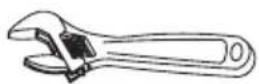
Adjustable Wrench
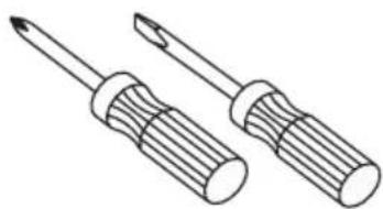
natural_image
Line drawing of two screwdrivers with threaded end caps (no text or symbols)Screwdrivers
SPECIFICATIONS
| Water Supply Pressure | Minimum required: 20 psi (138 kPa) (Flowing) |
| Maximum allowed: 80 psi (551 kPa) | |
| Water Supply Connection NPSM 1/2 | |
| Ambient Temperature 32~104°F (0~40°C) | |
| Humidity Max. 90% RH | |
| Flow Rate Maximum 1 | 2 gallon/min (4.5 L/min) |
INSTALLATION PROCEDURE
Valves
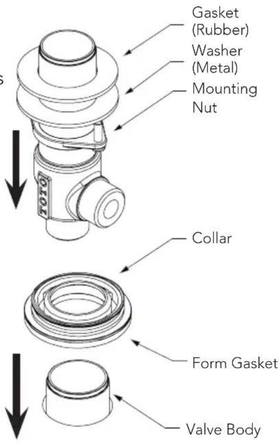
- Thread a mounting nut to the bottom of the valve. Place a washer and gasket as shown.
NOTE: the hot water valve has a red marking on side of body.
-
Pass the valve up through the installation hole. Insert the gasket and fasten the collar to the valve body until it stops.
-
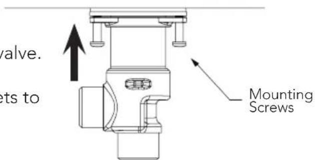
Fixate the valve by threading the mounting nut up the valve until hand tight. Tighten the retaining screws equally to secure.
Do not overtighten!
- Repeat steps 1-3 for remaining valve.
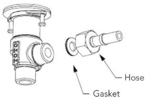
NOTE: Hoses to connect valve inlets to water supply lines not included.
Spout
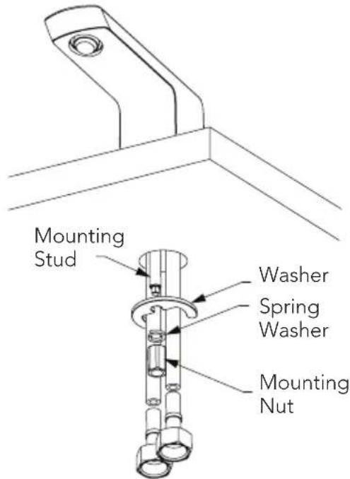
- Pass the supply hoses and mounting stud through the mounting hole until the spout comes to rest.


INSTALLATION PROCEDURE
- Orient the spout as needed. From below the mounting surface, place the crescent shaped gasket and washer over the mounting stud as shown.
Fasten the mounting nut to the stud to secure the spout.
Tighten with wrench as needed.
- Connect each hose to the side port of each valve. Tighten with wrench.
NOTE: If wrapping the hose(s) in a loop is needed, be careful not to crimp the hose at any point at this could restrict the water flow.
Handles
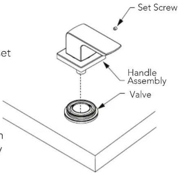
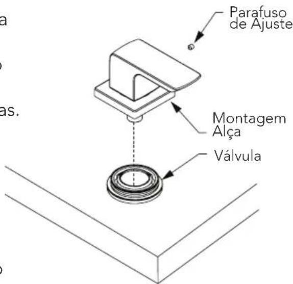
- Orient handle assembly and lower onto the exposed portion of valve until engaged. Fasten handle escutcheon to collar with provided set screw. Repeat for other handle assembly.
NOTE: If handles do not line up exactly as desired, remove handle from valve and reinstall one (1) notch over (on valve). Fine adjustment may be done by slightly rotating valve from underneath installed surface.
INSTALLATION PROCEDURE
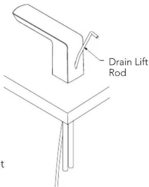
- Insert the drain lift rod through the opening in the spout.
Drain
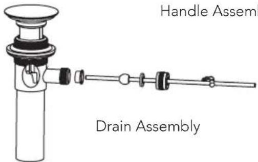
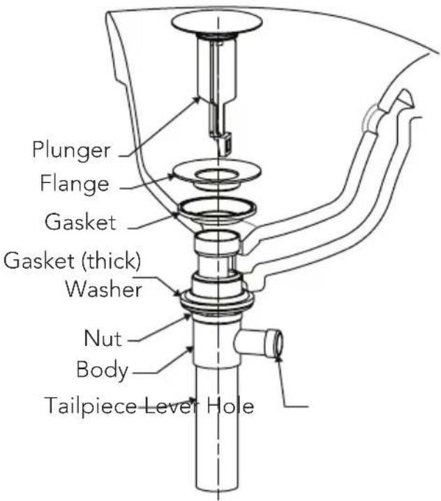
- Remove the plunger, flange and gasket from the drain assembly by unfastening the flange and pulling these parts from the drain.
Insert the drain body up through the drain hole from below the lavatory. If necessary, turn the nut and push the washer and gasket (thick) down to allow for clearance.
While holding the drain body in place, fasten the flange to the drain body from the top. Ensure that the gasket (flat) is between the flange and the lavatory as shown. Once the flange is fully seated, turn the nut below the lavatory up until a good seal is formed. Do not overtighten!
Reinsert the plunger if needed.
INSTALLATION PROCEDURE
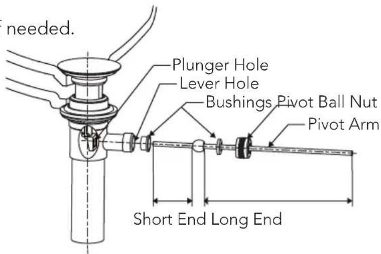
- Prepare the pivot arm by placing one bushing on each side of the pivot ball as shown. Insert the short end of the rod into the drain body and through the eyelet hole in the plunger.
Fasten the pivot ball nut to secure.
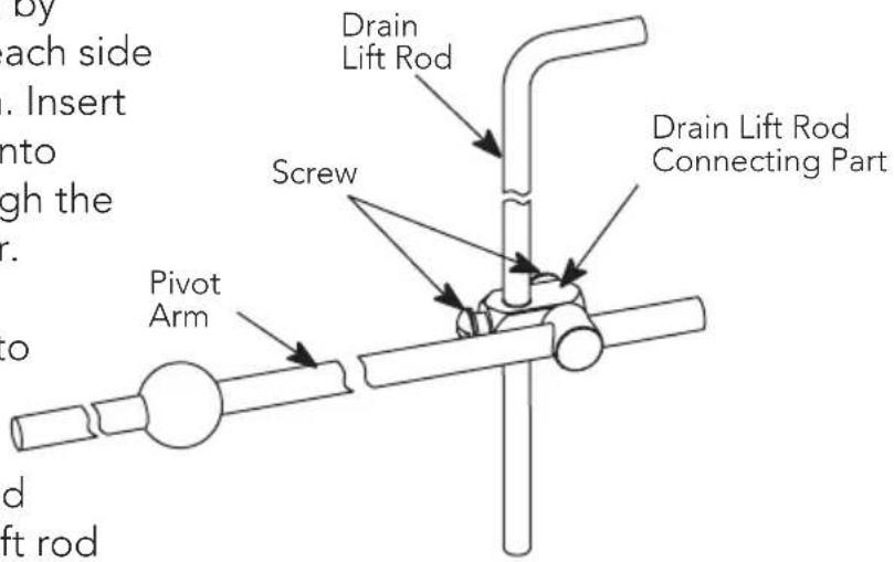
Insert the drain lift rod and pivot arm into the drain lift rod connecting part.
Tighten both rods with screwdriver.
WARRANTY
1. TOTO ever("Product") to be free from defects and soap dispens
materials and workmanship during normal use when properly installed and serviced, for a period of three (3) years from date of purchase. This limited warranty is extended only to the ORIGINAL PURCHASER of the Product and is not transferable to any third party, including but not limited to any subsequent purchaser or owner of the Product. This warranty applies only to TOTO Product purchased and installed in North, Central and South America.
- TOTO's obligations under this warranty are limited to repair, replacement or other appropriate adjustment, at TOTO's option, of the Product or parts found to be defective in normal use, provided that such Product was properly installed, used and serviced in accordance with instructions. TOTO reserves the right to make such inspections as may be necessary in order to determine the cause of the defect. TOTO will not charge for labor or parts in connection with warranty repairs or replacements. TOTO is not responsible for the cost of removal, return and/or reinstallation of the Product.
3. This warranty does not apply to the following items:
a. Damage or loss sustained in a natural calamity such as fire, earthquake, flood, thunder, electrical storm, etc.
b. Damage or loss resulting from any accident, unreasonable use, misuse, abuse, negligence, or improper care, cleaning, or maintenance of the Product.
c. Damage or loss resulting from sediments or foreign matter contained in a liquid soap system.
d. Damage or loss resulting from improper installation or from installation of the Product in a harsh and/or hazardous environment, or improper removal, repair or modification of the Product.
e. Damage or loss resulting from electrical surges or lightning strikes or other acts which are not the fault of TOTO or which the Product is not specified to tolerate.
f. Damage or loss resulting from normal and customary wear and tear, such as gloss reduction, scratching or fading over time due to use, cleaning practices or water or atmospheric conditions, including but not limited to, the use of bleach, alkali, acid cleaners, dry (powder) cleaners or any other abrasive cleaners or the use of metal or nylon scrubbers.
- In order for this limited warranty to be valid, proof of purchase is required. TOTO encourages warranty registration upon purchase to create a record of Product ownership at http://www.totousa.com is required. TOTO encourages registration upon purchase and failure to register will not diminish your limited warranty rights.
- THIS WARRANTY GIVES YOU SPECIFIC LEGAL RIGHTS. YOU MAY HAVE OTHER RIGHTS WHICH VARY FROM STATE TO STATE, PROVINCE TO PROVINCE OR COUNTRY TO COUNTRY.
- To obtain warranty repair service under this warranty, you must take the Product or deliver it prepaid to a TOTO service facility together with proof of purchase (original sales receipt) and a letter stating the problem, or contact a TOTO distributor or products service contractor, or write directly to TOTO U.S.A., INC., 1155 Southern Road, Morrow, GA 30260 (888) 295 8134 or (678) 466-1300, if outside the U.S.A. If, because of the size of the Product or nature of the defect, the Product cannot be returned to TOTO, receipt by TOTO of written notice of the defect together with proof of purchase (original sales receipt) shall constitute delivery. In such case, TOTO may choose to repair the Product at the purchaser's location or pay to transport the Product to a service facility.
THIS WRITTEN WARRANTY IS THE ONLY WARRANTY MADE BY TOTO. REPAIR, REPLACEMENT OR OTHER APPROPRIATE ADJUSTMENT AS PROVIDED UNDER THIS WARRANTY SHALL BE THE EXCLUSIVE REMEDY AVAILABLE TO THE ORIGINAL PURCHASER. TOTO SHALL NOT BE RESPONSIBLE FOR LOSS OF THE PRODUCT OR FOR OTHER INCIDENTAL, SPECIAL OR CONSEQUENTIAL DAMAGES OR EXPENSES INCURRED BY THE ORIGINAL PURCHASER, OR FOR LABOR OR OTHER COSTS DUE TO INSTALLATION OR REMOVAL, OR COSTS OF REPAIRS BY OTHERS, OR FOR ANY OTHER EXPENSE NOT SPECIFICALLY STATED ABOVE. IN NO EVENT WILL TOTO'S RESPONSIBILITY EXCEED THE PURCHASE PRICE OF THE PRODUCT. EXCEPT TO THE EXTENT PROHIBITED BY APPLICABLE LAW, ANY IMPLIED WARRANTIES, INCLUDING THAT OF MERCHANTABILITY OR FITNESS FOR USE OR FOR A PARTICULAR PURPOSE, ARE EXPRESSLY DISCLAIMED. SOME STATES DO NOT ALLOW LIMITATIONS ON HOW LONG AN IMPLIED WARRANTY LASTS, OR THE EXCLUSION OR LIMITATION OF INCIDENTAL OR CONSEQUENTIAL DAMAGES, SO THE ABOVE LIMITATION AND EXCLUSION MAY NOT APPLY TO YOU.
TABLA DE CONTENIDO
natural_image
Technical line drawing of a mechanical device with two flanged ends and a central lever (no text or symbols)natural_image
Simple line drawing of a bent tool or tube with a central handle (no text or symbols)Vara de Desagüe
natural_image
Isometric line drawing of a mechanical component with a flanged top and base (no text or symbols)Ensamblaje de Manija (2x)

Llave del
Aireador
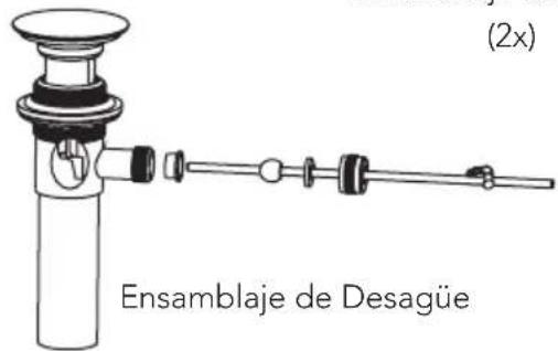
natural_image
Line drawing of two screwdrivers with different end caps (no text or symbols)Destornilladores
ESPECIFICACIONES
natural_image
Technical line drawing of a mechanical device with two connectors and a lever (no text or symbols)natural_image
Simple line drawing of a bent tube or rod with a central cap (no text or symbols)natural_image
Technical line drawing of a mechanical component with no visible text or symbolsnatural_image
Simple line drawing of a mechanical component with a flanged top and base (no text or symbols)natural_image
Line drawing of two screwdrivers with no text or symbolsTournevis
CARACTÉRISTIQUES
natural_image
Technical line drawing of a mechanical device with two flanged ends and a central support (no text or symbols)Conjunto do Bico
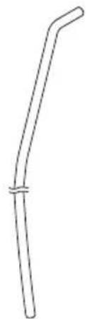
natural_image
Simple line drawing of a bent pipe or rod with a looped end (no text or symbols)natural_image
Technical line drawing of a mechanical component with no visible text or symbolsnatural_image
Simple line drawing of a mechanical component with a base and top (no text or symbols)Conjunto de Alças (2x)

Chave do
Aerador
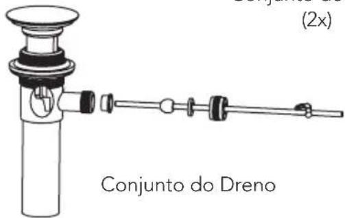
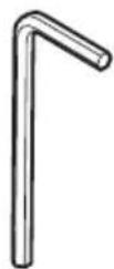
Chave
Sextavada
(2 mm)
natural_image
Line drawing of two screwdrivers with no text or symbolsChave de Fenda
ESPECIFICAÇÕES
natural_image
Technical line drawing of a mechanical valve or fitting component (no text or symbols visible)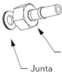
Mangueira
GO Widespread Lavatory Faucet
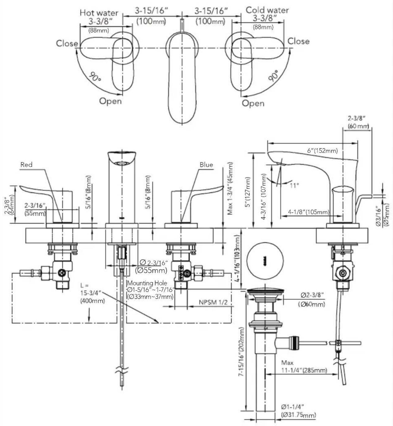
TLG01201
Note: The above dimensional unit is inches. The dimension in () is mm.
ROUGH-IN DIMENSIONS / BOSQUEJO ROBINETTERIE BRUTE / DIMENSÕES APROXIMADAS
GR Widespread Lavatory Faucet
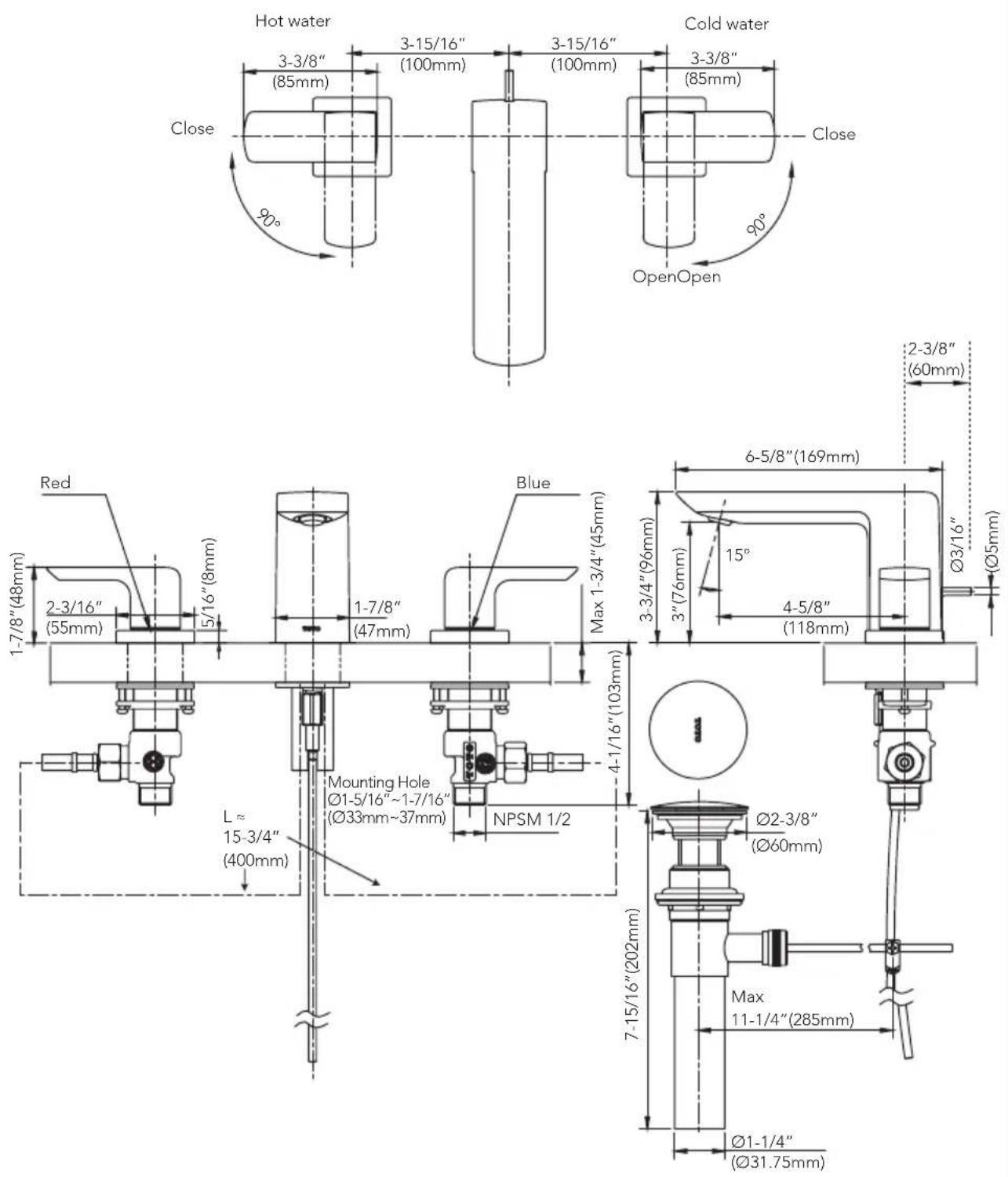
TLG02201
Note: The above dimensional unit is inches. The dimension in ( ) is mm.
ROUGH-IN DIMENSIONS / BOSQUEJO ROBINETTERIE BRUTE / DIMENSÕES APROXIMADAS
GS Widespread Lavatory Faucet
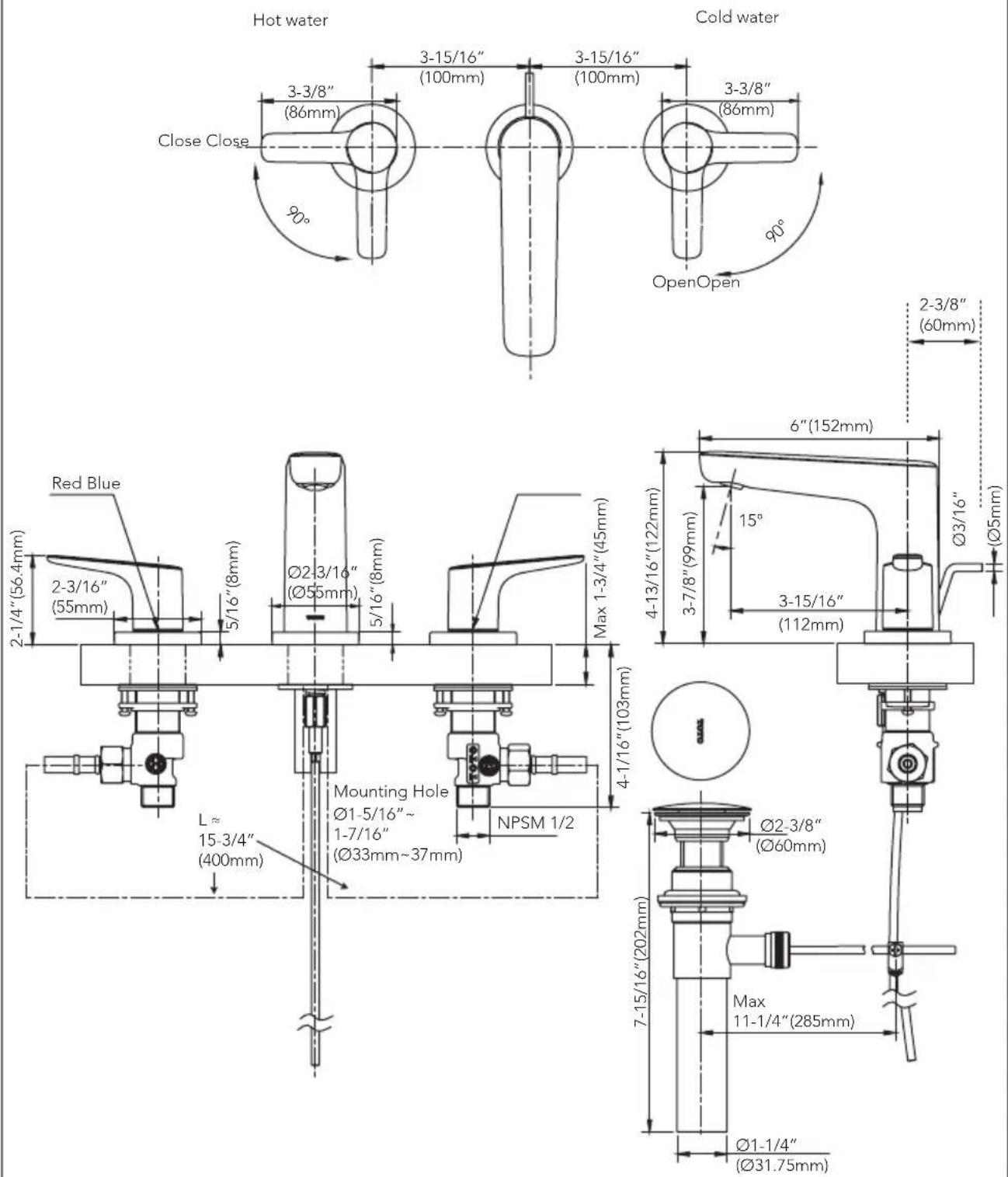
TLG03201
Note: The above dimensional unit is inches. The dimension in ( ) is mm.
NOTES
NOTES
NOTES
TOTO
TOTO U.S.A., Inc. 1155 Southern Road,
Morrow, Georgia 30260
Tel: 888-295-8134 Fax: 800-699-4889
www.totousa.com
0GU4275
Rev B


- INCLUDED PARTS
- TOOLS YOU WILL NEED
- INSTALLATION PROCEDURE
- Valves
- Spout
- Handles
- Drain
- WARRANTY
- TOTO ever("Product") to be free from defects and soap dispens
- This warranty does not apply to the following items:
- ESPECIFICACIONES
- CARACTÉRISTIQUES
- ESPECIFICAÇÕES
- TLG01201
- ROUGH-IN DIMENSIONS / BOSQUEJO ROBINETTERIE BRUTE / DIMENSÕES APROXIMADAS
- TLG02201
- TLG03201
- NOTES
- TOTO
Brand : TOTO
Model : TLG03201U
Category : Faucet