
LMSLN400AW1 - Fridge DAIKIN - Free user manual and instructions
Find the device manual for free LMSLN400AW1 DAIKIN in PDF.

User questions about LMSLN400AW1 DAIKIN
0 question about this device. Answer the ones you know or ask your own.
Ask a new question about this device
Download the instructions for your Fridge in PDF format for free! Find your manual LMSLN400AW1 - DAIKIN and take your electronic device back in hand. On this page are published all the documents necessary for the use of your device. LMSLN400AW1 by DAIKIN.
USER MANUAL LMSLN400AW1 DAIKIN
Monoblock System for Refrigeration
Installation & Operating Manual Monoblock for Refrigeration
natural_image
Illustration of a forklift and two stacked storage tanks with upward arrows indicating motion (no text or symbols)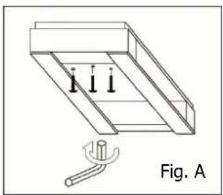
natural_image
Technical line drawing of a mechanical assembly with three vertical supports and a tool, labeled Fig. A (no text or symbols on the diagram itself)
AVVERTENZE
natural_image
Simple geometric diagram with a rectangle and two small squares, labeled 'E' at the bottom (no text or symbols within the diagram itself)| Mod. | A | B | C | E | F | G |
| LMSMD030-050-060-075-100/LMSLN100-120-170 767 310 535 485 845 40 | ||||||
| LMSMD102-120-122-130 / LMSLN172-200 767 310 535 785 845 40 | ||||||
| LMSMD150-200 / LMSLN300 860 400 670 760 1070 50 |
| Mod. | B | C | D | E | F | G |
| LMSMD030-050-060-075-100/LMSLN100-120-170 | 324 | 295 | 80 | 55 | 147,5 | 147,5 |
| LMSMD102-120-122-130 / LMSLN172-200 | 324 | 595 | 80 | 55 | 297,5 | 297,5 |
| LMSMD150-200 / LMSLN300 | 400 542 65 85 | 271 271 | ||||
- Safety recommendations
- Table of warning and attention plates
- Description of the unit
- Operation
-
Handling
-
Installation
6.1 Plates
6.2 Dimensions
6.3 Location
6.4 Free room
6.5 Installation
6.6 Safety devices
6.7 Cleaning
- Connecting the unit
7.1 Electric connection
- Electrical control
8.1 Control panel
8.2 Pushbuttons and signals on the electronic control panel
8.3 Istruction to display the parameters
- Checks, regulations and adjustments
9.1 Starting
-
Wiring
-
Maintenance and repairs
-
Routine maintenance
12.1 Periodical maintenance
12.2 Service operations to be carried out by qualified technicians or by the manufacturer
12.3 Troubleshooting
12.4 Alarms
-
How to order spare parts
-
How to dispose of the packing
-
How to dispose of the unit
Thank you for choosing Daikin.
Please read these instructions carefully. They provide details and advice on the correct method of installing, using and maintaining this unit, in order to obtain maximum reliability, efficiency and long life.
1 Safety recommendations
When installing and using the unit please follow the recommendations listed here below.
- Installation shall be carried out in strict compliance with the diagrams and instructions supplied by the manufacturer.
• Damages due to improper connections are excluded. - The electric system available where the unit is installed shall meet the relevant standards in force.
- Maintenance shall be effected by trained personnel or by the manufacturer according to the provisions supplied by EN378.
WARNING
Use safety gloves to protect your hands from possible cuts.
The user is strongly recommended to contact the manufacturer before attempting any intervention on the unit and any use not corresponding to the manufacturer's indications (in particular as for the field of application) and to enquire about the possible dangers and contra-indications connected with an improper use of the machine.
- The unit shall be used following these instructions and sticking to the destination of use indicated by the supplier. Any incorrect use can result in damages to the unit and represents a serious danger for people's health.
ATTENTION
The unit is not suitable for working in explosive environments.
Therefore the use of the unit in an explosion-dangerous atmosphere is absolutely forbidden.
ATTENTION
The unit is not suitable for working in salty environments. In such a case protect condenser and evaporator with appropriate means.
When maintenance involves operations on the refrigerating circuit, empty the system and let it reach the atmospheric pressure.

WARNING
Do not discharge the refrigerant in the atmosphere. It must be recovered by specialized technicians using suitable equipment.
• Quantity and quality of the refrigerant to be charged are indicated on the data plate.
- Do not use refrigerants of different kind (especially inflammable fluids, for example hydrocarbons) or air.
- Do not modify or alter the refrigerating circuit or its components (for example: welding on compressor body)
- The final user shall protect the system from external fire dangers.
2 Table of warning and attention plates
DAIKIN EUROPE N.V.
Zandroordeimat 300,8-8400 Ostende, Belgium
CE
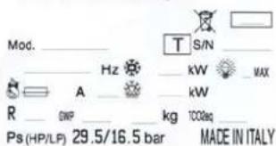
 | Refrigerant |
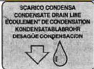 | Condensate drain line |
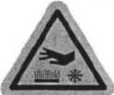 | Attention: hot or cold parts |
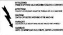 | Attention: switch off before operating on the unit. |
 | Attention: danger of electrocution |
 | Connect this cable to a circuit breaker, never to the main line directly. |
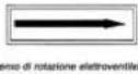 | Direction of rotation |
 | Colours of supply cable wires |
 | Attention - important : clean the condenser periodically by blowing air from the inside outwards.Stop the unit before cleaning. |
3 Description of the unit
The LMS series includes air-cooled condensing units built on the basis of the single-block principle. They consist of:
- a condensing unit placed outside the cold room;
- an evaporator installed inside the room;
- an electric control panel placed on the condensing unit;
4 Operation
LMS single blocks are compression units where cold is produced by vaporizing a liquid refrigerant (HFC type) at low pressure in a heat exchanger (evaporator). The resulting vapour is brought again into the liquid state by mechanical compression at a higher pressure, followed by cooling in another heat exchanger (condenser).
The compressor is hermetic, with reciprocating motion, supplied with single-phase or three-phase power. Defrost takes place automatically in pre-set cycles, by means of heaters; manual defrost is also possible.
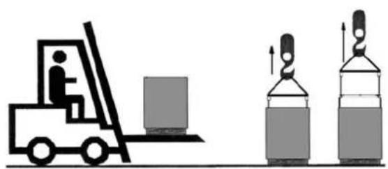
5 Handling
The unit can be handled by lifting and transport means.
UNSCREW THE FIXING SCREWS TO REMOVE CRATING FROM THE UNIT. (fig. A).
natural_image
Illustration of a forklift and two gas cylinders (no text or symbols)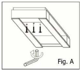
natural_image
Technical line drawing of a mechanical assembly with three vertical pins and a base, labeled Fig. A (no text or symbols on the diagram itself)WARNING
Make sure that no one is in transit in the operating area of the lifting/transport means to prevent any possible accidents to people.
If the unit is in a wooden case or crate, sling the packing properly before handling it.
Lifting speed shall be such as not to make the packed unit oscillate dangerously and possibly fall.
6 Installation
6.1 Plates
The unit is supplied with warning and attention plates as listed in the relevant table.
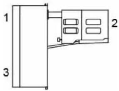
6.2 Dimensions
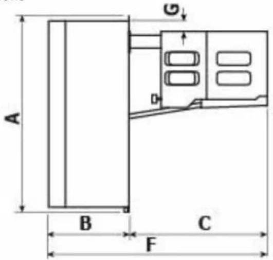
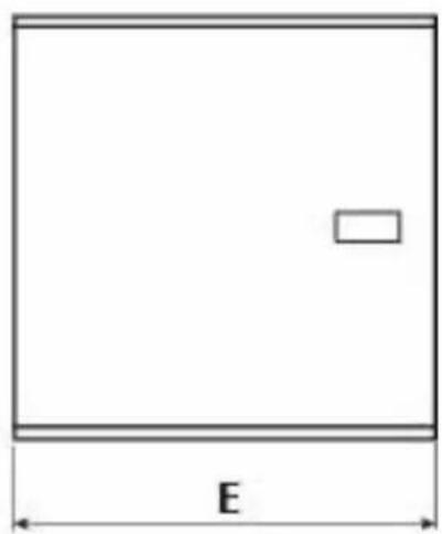
natural_image
Simple geometric diagram of a rectangle with a small rectangle inside and labeled dimension 'E' (no text or symbols beyond the label)| Mod. | A | B | C | E | F | G |
| LMSMD030-050-060-075-100/LMSLN100-120-170 767 310 535 485 845 40 | ||||||
| LMSMD102-120-122-130 / LMSLN172-200 767 310 535 785 845 40 | ||||||
| LMSMD150-200 / LMSLN300 860 400 670 760 1070 50 |
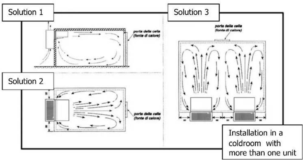
6.3 Location
To obtain optimal operation of the unit act as follows:
A) Place the unit in a well ventilated room, far from heat sources.
B) Limit the number of door openings.
C) Make sure that the unit has good air supply and discharge.
D) Fit a drain line to the defrost water drain connection in the lower part of the unit.
Note: LMS units are equipped with automatic evaporation of defrost water; drain is just a precaution in case of troubles.
When installing the unit leave enough free room to allow opening, correct use and easy maintenance in safe conditions.
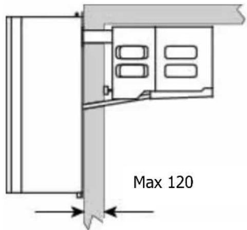
6.5 Installation
Straddle version:
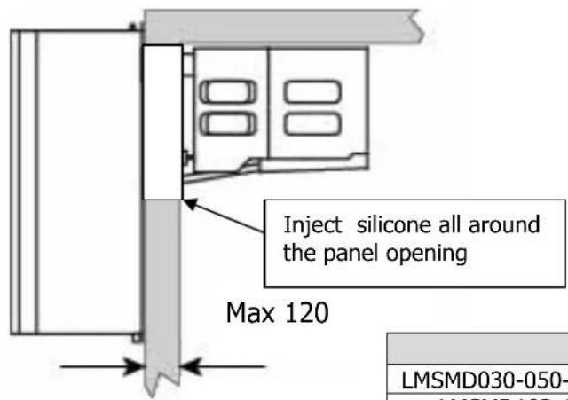
Before mounting the unit prepare the cuts in the cold room wall as shown in the picture. Fix the unit in place with the appropriate screws. Position the unit on the cold room, connect the evaporator drain tray spigot and the hole prepared in the cold room wall using the supplied pipe with pre-inserted heater (for low temperature units only). Fill the hole in the wall with insulating material, polyurethane or silicone, and mount the hole cover.
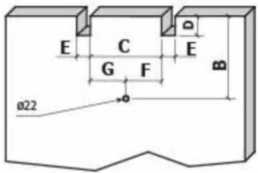
| Mod. | B | C | D | E | F | G |
| LMSMD030-050-060-075-100/LMSLN100-120-170 324 295 80 55 147,5 147,5 | ||||||
| LMSMD102-120-122-130 / LMSLN172-200 324 595 80 55 297,5 | 297,5 | |||||
| LMSMD150-200 / LMSLN300 400 542 65 85 271 | 271 |
Thru-wall version (optional):
A) Prepare a opening with suitable dimensions in the cold room wall (see picture).
B) Position the unit onto the cold room wall inserting the evaporator section in the opening.
C) Fix the unit using the screws supplied.
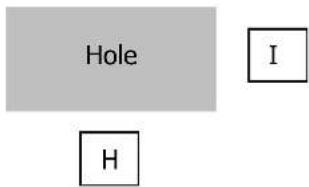
| Mod. H I | ||
| LMSMD030-050-060-075-100/LMSLN100-120-170 | 425 | 335 |
| LMSMD102-120-122-130 / LMSLN172-200 | 725 | 335 |
| LMSMD150-200 / LMSLN300 | 725 | 475 |
ATTENTION
Check that the unit and its devices have suffered no damages during transport. Pay special attention to the components
secured to the electric panel door and to the refrigerating circuit pipes. Mount the unit as shown in the drawings; make sure that the electric connections are carried out properly.
6.6 Safety devices
The following mechanical safety devices are supplied:
- Fixed upper and side protections for evaporator and condensing unit, secured by locking screws.
- External fan protections placed on the evaporating and condensing units, secured with screws.
The following electrical safety devices are supplied:
a. Protection of fans (belonging to motors) against high power absorption; with automatic reset.
b. High pressure switch (only for special components) to protect against excessive pressure; with automatic reset.
WARNING
Above devices have been developed to safeguard the operator's safety.
6.7 Cleaning
Clean the unit carefully. Remove any dust, foreign substances and dirt possibly deposited during handling. Use detergents and degreasers.

ATTENTION
Solvents are not allowed.
7 Connecting the unit

ATTENTION
Before connecting the unit make sure that mains voltage and frequency correspond to the values shown in the data plate. Voltage tolerance: +/- 10% compared to nominal value.
7.1 Electric connection
Connect the unit after checking the panel components.

ATTENTION
Connection to the electric line shall be effected applying a suitable safety device (a circuit breaker or a ground fault interrupter) selected by the installer on the basis of the line involved and of the absorption indicated on the unit plate.
If a cold room includes more units, each unit shall be provided with its own safety device. Connect the unit paying attention to the colours of the supply cable wires:
| a) 230V/1/50-60Hz 3 wires Yellow/Green = Ground | |||||||
| B | r | o | w | n | = | P | |
| b) 230V/3/50-60Hz 4 wires Grey = Phase | |||||||
| Yellow/Green = Ground | |||||||
| Brown = Phase | |||||||
| B | l | a | c | k | = | P | |
| c) 400/3/50 Hz | 5 wires Blue = Neutral |
| Yellow/Green = Ground |
| B | r | o | w | n | = | P |
| B | l | a | c | k | = | P |
| G | r | e | y | = | P | h |
8 Electrical control
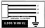
8.1 Control panel
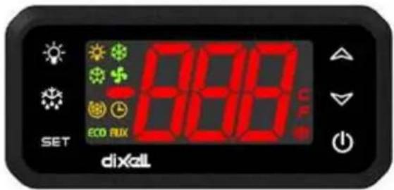
Electronic control unit: it can adjust the cold room temperature and control all the functions of the refrigerating system.
8.2 Pushbuttons and signals on the electronic control panel
| SET | SET | To display target set point; in programming mode it selects a parameter or confirm an operation |
| Def |  | To start a manual defrost |
| Up | [22YA] | (UP): To see the max. stored temperature; in programming mode it browses the parameter codes or increases the displayed value. |
| Down | [5K2K] | To see the min stored temperature; in programming mode it browses the parameter codes or decreases the displayed value. |
| ON/OFF |  | To switch the instrument off |
| Light |  | To switch on or off the coldroom light |
Meaning of the led's
A number of points is located on the display whose meaning is described in the following table.
 | Compressor LedFixed on Compressor enabledFlashing Anti-short cycle delay enabled |
 | Defrost Led (De-frosting)Fixed on: Defrost enabledFlashing: Drip time in progress |
 | Fan LedFixed on: Fans enabledFlashing Fans delay after defrost in progress |
8.3 Instruction to display the parameters
HOW TO SEE THE SET POINT:
Push and immediately release the SET key: the display will show the Set point value;
Push and immediately release the SET key or wait for 5 seconds to display the probe value again
HOW TO CHANGE THE SET POINT
Push the SET key for more than 2 seconds to change the Set point value;
The value of the set point will be displayed and the "°C" or "°F" LED starts blinking;
To change the Set value push the o or n arrows within 10s.
To memorise the new set point value push the SET key again or wait 10s.
HOW TO START A MANUAL DEFROST
Push the DEF key for more than 2 seconds and a manual defrost will start.
COLDROOM LIGHT:
The coldroom light is switched on when the key (LIGHT) is pressed.
ON/OFF function:
When the ON/OFF key is pressed, the equipment is set to stand-by and displays OFF. In this configuration the unit is not active. To set the equipment to ON press the key again.
WARNING
The unit is powered even when OFF continues to be displayed on the control unit.
9 Checks, regulations and adjustments
Before turning the unit on, check that:
- locking screws are tight
- electrical connections have been carried out correctly.
In the event that the unit has been opened:
- no tools were left inside
- assembly is correct
- there are no gas leaks
- front cover is secured correctly
9.1 Starting
Before starting the unit act as follows:
- Connect the unit to the mains. The luminous switch lights up
- If the unit has a preheating cycle, leave it in this condition for at least 3 hours.
- If the unit has a voltage monitor, leave it in this condition for at least 7 minutes to have the counting phase carried out
- Switch on the control by pressing key 0/1.
- Set the required cold room temperature.

ATTENTION
Medium temperature range: +5 -5°C
Low temperature range : -18 -25°C

ATTENTION
24 hours after starting check evaporator state. If ice has formed, defrost frequency should be increased. In low temperature units the evaporator condition should be checked every week during the first month of operation.
10. Wiring
A wiring diagram, specific for the units of the LMS series, is enclosed with these use and maintenance instructions.
11. Maintenance and repairs
Suitable maintenance is crucial for obtaining longer life, perfect working conditions and high efficiency of the unit as well as for ensuring the safety features provided by the manufacturer.
12 Routine maintenance
Good operation of the unit requires the condenser to be cleaned periodically (frequency of cleaning depends on the environment where the unit is installed).
Turn off the unit and clean it by blowing air from the inside outwards. Should no air jet be available, use a long-haired brush and work on the outside of the condenser.
In case of water-cooled condensers have the unit cleaned by a plumber with special descaling agents.
WARNING
Use safety gloves to protect your hands from possible cuts.
WARNING
Disconnect the unit before working on it.
12.1 Periodical maintenance
Periodically check wear condition of electrical contacts and remote switches; if necessary replace them.
12.2 Service operations to be carried out by qualified technicians or by the manufacturer
Following operations shall be carried out by qualified technicians or by the manufacturer exclusively. Under no circumstances the user is allowed to:
- replace electrical components
• work on the electric equipment
• repair mechanical parts
• work on the refrigerating system - work on the control panel, ON/OFF and emergency switches
• work on protection and safety devices.
12.3 Troubleshooting
During operation following troubles may occur:
1 Compressor stops. The unit is equipped with an overtemperature device which stops the compressor every time the max. allowable temperature of motor windings is exceeded. Possible causes are:
- insufficient ventilation of the room where the unit is installed;
- anomaly in mains voltage;
- faulty operation of condenser fan.
Device reset is automatic.
2 Ice forms on the evaporator preventing air from flowing regularly.
Possible causes are:
- the door is opened too frequently;
- faulty operation of evaporator fan;
- faulty solenoid valve (in models with hot gas defrost);
- faulty defrost heater (in models with electric defrost);
- faulty defrost process. In this case some measures can be taken:
increase defrost termination temperature by some degrees, increase number of defrosts.
ATTENTION
Do not use either hot water or any pointed, cutting, metal objects to remove ice blocks.
3. Display does not light up. Check:
- if there is power to the unit;
- if mains cable is connected properly;
- fuses inside the electric panel
Unsatisfactory efficiency of the unit:
If no defects are found in the unit check that: cold room doors are perfectly tight dispersion; the cold room is used wisely; no unfrozen liquids or foodstuffs are placed in the low temperature room; the evaporator is ice-free.
We recommend installation of the machines far from the doors especially when the cold room is expected to be opened many times a day.

WARNING:
Removal of protections during machine operation is absolutely forbidden. They have been developed to safeguard the operator's safety.
12.4 Alarms
| Label | Failure | Cause | Problem resolution |
| P1 | Environment probe (Pb1) | values outside the operation rangefailed / shortcircuited / open probe | check the type of probe (NTC)check the wiring of probesreplace the probe |
| P2 | End of de-frosting probe (Pb2) | values outside the operation rangefailed / shortcircuited / open probe | check the type of probe (NTC)check the wiring of probesreplace the probe |
| CA | HIGH/LOW pressure alarm | Overcoming of the High/Low pressure value, read by the corresponding pressure switches (it is over the highest allowed differential value). | Check the pressure switch efficiency.Check if the condenser is clean or if the condenser fan is correctly working. |
| dA | Door open | check if the coldroom has the door open, its seal, introduction of hot product etc. |
13 How to order spare parts
When ordering spare parts make reference to the number written on the unit plate.
WARNING
Worn parts should be replaced only by qualified personnel or by the manufacturer.
14 How to dispose of the packing
Wooden, plastic, polystyrene packing shall be disposed of according to the regulations in force in the country where the unit is used.
15 How to dispose of the unit
Do not discharge scrapped components in the environment. They should be disposed of by companies dealing with special waste collection and recovery, according to the regulations in force in the country where the unit is used.
WARNING
Do not discharge the refrigerant in the atmosphere. It sh companies dealing with special waste collection and recovery.
INDEX
natural_image
Illustration of a forklift and two gas cylinders (no text or symbols)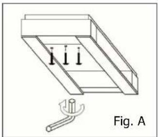
natural_image
Technical line drawing of a mechanical assembly with three vertical supports and a tool, labeled Fig. A (no text or symbols on the diagram itself)AVERTISSEMENTS

natural_image
Simple geometric diagram with a rectangle and dimension label 'E' (no text or symbols within the shape)| Mod. | A | B | C | E | F | G |
| LMSMD030-050-060-075-100/LMSLN100-120-170 767 310 535 485 845 40 | ||||||
| LMSMD102-120-122-130 / LMSLN172-200 767 310 535 785 845 40 | ||||||
| LMSMD150-200 / LMSLN300 860 400 670 760 1070 50 |
6.3 Mise en place de la machine
natural_image
Illustration of a forklift and two stacked storage tanks with upward arrows indicating motion (no text or symbols)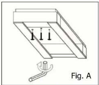
natural_image
Technical line drawing of a mechanical assembly with three downward arrows and a tool, labeled Fig. A (no text or symbols on the diagram itself)
HINWEISE
natural_image
Simple geometric diagram of a rectangle with a small rectangle inside and labeled dimension 'E' (no text or symbols beyond the label)| Mod. | A | B | C | E | F | G |
| LMSMD030-050-060-075-100/LMSLN100-120-170 767 310 535 485 845 40 | ||||||
| LMSMD102-120-122-130 / LMSLN172-200 767 310 535 785 845 40 | ||||||
| LMSMD150-200 / LMSLN300 860 400 670 760 1070 50 |
| Mod. | B | C | D | E | F | G |
| LMSMD030-050-060-075-100/LMSLN100-120-170 324 295 80 55 147,5 147,5 | ||||||
| LMSMD102-120-122-130 / LMSLN172-200 | 324 595 80 55 | 297,5 | 297,5 | |||
| LMSMD150-200 / LMSLN300 | 400 542 65 85 | 271 271 |

HINWEIS
natural_image
Illustration of a forklift and two stacked cylindrical tanks with upward arrows indicating motion (no text or symbols)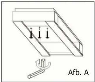
natural_image
Technical line drawing of a mechanical assembly with three vertical supports and a base, labeled 'Afb. A' (no text or symbols on the diagram itself)WAARSCHUWING

natural_image
Simple geometric diagram of a rectangle with a small rectangle inside and labeled dimension 'E' (no text or symbols beyond the label)| Mod. | A | B | C | E | F | G |
| LMSMD030-050-060-075-100/LMSLN100-120-170 767 310 535 485 845 40 | ||||||
| LMSMD102-120-122-130 / LMSLN172-200 767 310 535 785 845 40 | ||||||
| LMSMD150-200 / LMSLN300 860 400 670 760 1070 50 |
6.3 Locatie
| Mod. | B | C | D | E | F | G |
| LMSMD030-050-060-075-100/LMSLN100-120-170 324 295 80 55 147,5 147,5 | ||||||
| LMSMD102-120-122-130 / LMSLN172-200 324 595 80 55 297,5 | 297,5 | |||||
| LMSMD150-200 / LMSLN300 400 542 65 85 271 | 271 |
geel/groen = aarding
bruin = fase
b) 230V/3/50-60Hz
4 draden
grijs = fase
geel/groen = aarding
bruin = fase
zwart = fase
c) 400/3/50 Hz
5 draden
blauw = neutraal
geel/groen = aarding
bruin = fase
zwart = fase
grijs = fase
WAARSCHUWING
- Monoblock System for Refrigeration
- AVVERTENZE
- Safety recommendations
- WARNING
- ATTENTION
- Table of warning and attention plates
- Description of the unit
- Operation
- Handling
- Installation
- Plates
- Dimensions
- Location
- Installation
- Straddle version:
- Thru-wall version (optional):
- Safety devices
- Cleaning
- Connecting the unit
- Electric connection
- Electrical control
- Control panel
- Pushbuttons and signals on the electronic control panel
- Meaning of the led's
- Instruction to display the parameters
- HOW TO SEE THE SET POINT:
- HOW TO CHANGE THE SET POINT
- HOW TO START A MANUAL DEFROST
- COLDROOM LIGHT:
- ON/OFF function:
- Checks, regulations and adjustments
- Starting
- Wiring
- Maintenance and repairs
- Routine maintenance
- Periodical maintenance
- Service operations to be carried out by qualified technicians or by the manufacturer
- Troubleshooting
- Display does not light up. Check:
- Unsatisfactory efficiency of the unit:
- WARNING:
- Alarms
- How to order spare parts
- How to dispose of the packing
- How to dispose of the unit
- INDEX
- AVERTISSEMENTS
- Mise en place de la machine
- HINWEISE
- HINWEIS
- WAARSCHUWING
- Locatie
Brand : DAIKIN
Model : LMSLN400AW1
Category : Fridge