
LMCMD060AV3 - Fridge DAIKIN - Free user manual and instructions
Find the device manual for free LMCMD060AV3 DAIKIN in PDF.

| Product type | Monobloc refrigeration unit (refrigerator) |
| Brand | Daikin |
| Model | LMCMD060AV3 |
| Dimensions (L x H x D) | 357 x 719 x 250 mm (external part) |
| Additional dimensions | Evaporator: 332 x 506 x 28 mm ; Remote panel: 620 x 545 x 60 mm |
| Power supply | Single phase 230V / 50-60Hz or three-phase 400V / 50Hz |
| Refrigerant | R134a or R452A |
| Medium temperature regulation range | +5°C to -5°C |
| Low temperature regulation range | -18°C to -25°C |
| Main functions | Refrigeration compression, automatic defrost, electronic control, remote control panel |
| Routine maintenance | Cleaning the condenser with an air jet from inside to outside, machine stopped |
| Safety | Thermal protections, high pressure switch, door micro-switch, safety instructions |
| Spare parts | Order with the serial number on the nameplate |
| Repairability | Interventions reserved for qualified professionals |
| General information | Installation with free spaces, condensation water drainage, compressor preheating before startup |
Frequently Asked Questions - LMCMD060AV3 DAIKIN
User questions about LMCMD060AV3 DAIKIN
0 question about this device. Answer the ones you know or ask your own.
Ask a new question about this device
Download the instructions for your Fridge in PDF format for free! Find your manual LMCMD060AV3 - DAIKIN and take your electronic device back in hand. On this page are published all the documents necessary for the use of your device. LMCMD060AV3 by DAIKIN.
USER MANUAL LMCMD060AV3 DAIKIN
Monoblock System for Refrigeration
Installation & Operating Manual Monoblock for Refrigeration
- Safety recommendations
- Table of warning and attention plates
- Description of the unit
- Operation
-
Handling
-
Installation
6.1 Plates
6.2 Dimensions
6.3 Location
6.4 Free room
6.5 Installation
6.6 Fitting the remote panel
6.7 Safety devices
6.8 Cleaning
7 Connecting the unit
7.1 Electric connection
7.2 Connection to water system
- Electric controls
8.1 Control panel
- Checks, regulations and adjustments
9.1 Starting
9.2 How to Lock / Unlock the keyboard
-
Wiring
-
Maintenance and repairs
12 Routine maintenance
12.1 Periodical maintenance
12.2 Service operations to be carried out by qualified technicians or by the manufacturer
12.3 Troubleshooting
12.4 Alarms
13 How to order spare parts
14 How to dispose of the packing
15 How to dispose of the unit
Thank you for choosing Daikin.
Please read these instructions carefully. They provide details and advice on the correct method of installing, using and maintaining this unit, in order to obtain maximum reliability, efficiency and long life.
1 Safety recommendations
When installing and using the unit please follow the recommendations listed here below.
- Installation shall be carried out in strict compliance with the diagrams and instructions supplied by the manufacturer.
- Damages due to improper connections are excluded.
The electric system available where the unit is installed shall meet the relevant standards in force. - Maintenance shall be effected by trained personnel or by the manufacturer according to the provisions supplied by EN378.
WARNING
Use safety gloves to protect your hands from possible cuts.
The user is strongly recommended to contact the manufacturer before attempting any intervention on the unit and any use not corresponding to the manufacturer's indications (in particular as for the field of application) and to enquire about the possible dangers and contra-indications connected with an improper use of the machine.
- The unit shall be used following these instructions and sticking to the destination of use indicated by the supplier. Any incorrect use can result in damages to the unit and represents a serious danger for people's health.
ATTENTION
The unit is not suitable for working in explosive environments.
Therefore the use of the unit in an explosion-dangerous atmosphere is absolutely forbidden.

ATTENTION
The unit is not suitable for working in salty environments. In such a case protect condenser and evaporator with appropriate means.
When maintenance involves operations on the refrigerating circuit, empty the system and let it reach the atmospheric pressure.
WARNING
Do not discharge the refrigerant in the atmosphere. It must be recovered by specialized technicians using suitable equipment.
Quantity and quality of the refrigerant to be charged are indicated on the data plate.
- Do not use refrigerants of different kind (especially inflammable fluids, for example hydrocarbons) or air.
- Do not modify or alter the refrigerating circuit or its components (for example: welding on compressor body)
The final user shall protect the system from external fire dangers.
2 Table of warning and attention plates
DAIKIN EUROPE N.V.
| R134a R452A | Refrigerant |
| SCARICO CONDENSA CONDENSATE DRAIN LINE ECCULEMENT DE CONDENSATION KONDENSATABLABROHR DESAGUE CONDENSACION | Condensate drain line |
| Attention: hot or cold parts | |
| Attention: switch off before operating on the unit. | |
| ATTENZONI PERICOLE | Attention: danger of electrocution |
| Connect this cable to a circuit breaker, never to the main line directly. | |
| Direction of rotation | |
| Colours of supply cable wires | |
| Attention - important : clean the condenser periodically by blowing air from the inside outwards. Stop the unit before cleaning. | |
| Room light cable | |
| Microdoor cable | |
| Door heater cable | |
3 Description of the unit
The LMC series includes air-cooled or water-cooled (optional) condensing units built on the basis of the single-block principle. They consist of:
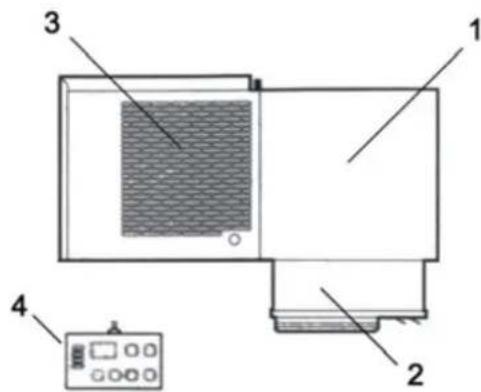
- a condensing unit placed outside the cold room;
- an evaporator placed in an insulated box and installed outside the cold room;
- an electric control panel placed on the condensing unit;
- a wall-mounted remote control panel.
4 Operation
LMC single blocks are compression units where cold is produced by vaporizing a liquid refrigerant (HFC type) at low pressure in a heat exchanger (evaporator). The resulting vapour is brought again into the liquid state by mechanical compression at a higher pressure, followed by cooling in another heat exchanger (condenser). The compressor is hermetic, with reciprocating motion, supplied with single-phase or three-phase power. Defrost takes place automatically in pre-set cycles; manual defrost is also possible.
5 Handling
The unit can be handled by lifting and transport means.
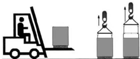

WARNING
Make sure that no one is in transit in the operating area of the lifting/transport means to prevent any possible accidents to people.

If the unit is in a wooden case or crate, sling the packing properly before handling it.
Lifting speed shall be such as not to make the packed unit oscillate dar possibly fall.
6 Installation
6.1 Plates
The unit is supplied with warning and attention plates as listed in the relevant table.
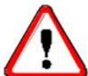
6.2 Dimensions
| Mod. A B C D E F G H I L M X Y | |||||||||||||||
| LMCMD050 / LMCLN100 | 378 | 250 | 784 | 307 | 120 | 27 | 301 | 525 | 60 | 430 | 350 | 306 | 355 | ||
| LMCMD060-075 / LMCLN170 | 357 | 250 | 719 | 340 | 122 | 28 | 332 | 506 | 60 | 620 | 545 | 337 | 550 | ||
| LMCMD100-120-122 / LMCLN200 | 390 | 250 | 809 | 360 | 122 | 28 | 332 | 540 | 60 | 820 | 745 | 337 | 750 | ||
| LMCMD150-200 / LMCLN300 | 427 | 250 | 929 | 410 | 122 | 98 | 452 | 645 | 60 | 820 | 745 | 456 | 750 | ||
| LMCMD300 | 542 | 250 | 1046 | 520 | 122 | 98 | 452 | 785 | 60 | 1075 | 1000 | 458 | 1005 | ||
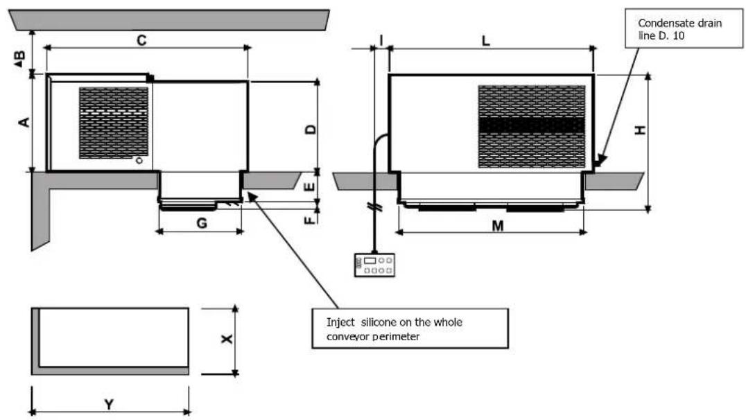
6.3 Location
To obtain optimal operation of the unit act as follows:
A) Place the unit in a well ventilated room, far from heat sources.
B) Limit the number of door openings.
C) Make sure that the unit has good air supply and discharge.
D) Fit a drain line to the defrost water drain connection in the lower part of the unit.
Note: LMC units are equipped with automatic evaporation of defrost water; drain is just a precaution in case of troubles.
6.4 Free room
When installing the unit leave enough free room to allow opening, correct use and easy maintenance in safe conditions.
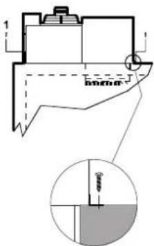
6.5 Installation
A) Prepare a opening with suitable dimensions in the cold room wall (see pictures above). Position the unit onto the cold room wall inserting the evaporator section in the opening.
B) Fix the unit using the screws supplied.
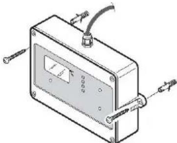
6.6 Fitting the remote panel:
Fix the back plate to the wall using the pre-drilled holes; be careful the panel is kept in a vertical position. Fit the connecting cable between panel and unit making sure not to bundle it with other cables.
ATTENTION
Check that the unit and its devices have suffered no damages during transport. Pay special attention to the components secured to the electric panel door and to the refrigerating circuit pipes. Mount the unit as shown in the drawings; make sure that the electric connections are carried out properly.
6.7 Safety devices
The following mechanical safety devices are supplied:
- Fixed upper and side protections for evaporator and condensing unit, secured by locking screws.
- External fan protections placed on the evaporating and condensing units, secured with screws.
The following electrical safety devices are supplied:
a. Protection of fans (belonging to motors) against high power absorption; with automatic reset.
b. High pressure switch (only for special components) to protect against excessive pressure; with automatic reset.
WARNING
Above devices have been developed to safeguard the operator's safety.
6.8 Cleaning
Clean the unit carefully. Remove any dust, foreign substances and dirt possibly deposited during handling. Use detergents and degreasers.

ATTENTION
Solvents are not allowed.
7 Connecting the unit
ATTENTION
Before connecting the unit make sure that mains voltage and frequency correspond to the values shown in the data plate. Voltage tolerance: +/- 10% compared to nominal value.
7.1 Electric connection
Connect the unit after checking the panel components.

ATTENTION
Connection to the electric line shall be effected applying a suitable safety device (a circuit breaker or a ground fault interrupter) selected by the installer on the basis of the line involved and of the absorption indicated on the unit plate.
If a cold room includes more units, each unit shall be provided with its own safety device.
Connect the unit paying attention to the colours of the supply cable wires:
a) 230V / 1 / 50 - 60Hz 3 wires
Blue = Neutral
Yellow/Green = Ground
Brown = Phase
b) 230V / 3 / 50 - 60Hz 4 wires
Grey = Phase
Yellow/Green = Ground
Brown = Phase
Black = Phase
c) 400 / 3 / 50Hz 5 wires
Blue = Neutral
Yellow/Green = Ground
| B | r | o | w | n | = | I | ||
| B | I | a | c | k | = | P | ||
| G | r | e | y | = | P | H |
We advise to install a microswitch (not supplied) on the cold room door which will
-
switch on the light in the cold room, stop the unit and
-
override the temperature alarm (for about one hour after door closing)
every time the door is opened.
The necessary cable is available with the unit. Connect it keeping in mind the following:
microswitch closed = door closed.
ATTENTION
Above microswitch is not supplied with the unit. If the microdoor cable is disconnected or damaged, the same conditions will occur as in case of open door and connected microdoor.
"LN" RANGE units (LN = low temperature) are supplied with a cable for door heater connection, to be made using a fuse suitable for the door heater used.
The unit is also equipped with a cable for cold room lamp connection (lamp voltage should be 230V and lamp max capacity 100 Watts).
ATTENTION
Do not connect microdoor, cold room light or door heater cables to the 230V line. Each cable is equipped with a plate showing how it should be connected.

WARNING
Any defective electrical part should be replaced by trained personnel exclusively. The electric connection should be effected by qualified personnel.
7.2 Connection to water system (water condenser)
This connection is only necessary if the unit has a water-cooled condenser. It is effected by following the indications of the tags positioned by the INLET and OUTLET pipes. Connection pipes should never be smaller in diameter than those on the unit. A minimum water pressure of 1 bar is required for correct operation of the unit.
8 Electric controls
8.1 Control panel

SET: SET POINT display: By pressing and releasing this key the set point is displayed.
SET POINT change: By pressing the key for 3s the set point value is displayed and the set point change mode is entered: the SET led blinks. In order to change the value use the and keys.
Then, the new value can be stored either by pressing the "SET" key (the instrument restores temperature display) or by waiting the programming exit timeout (15s).

UP : In the programming mode or in the "Function Menu" it browses the parameter codes or increases the value of the variable displayed. Keep pressed for a faster change.
Manual defrost: by pressing it for 5s the defrost cycle will start

DOWN : In programming mode or in "Function Menu" it browses the parameter codes or decreases the value of the variable displayed. Keep pressed for a faster change.

LIGHT: It switches on and off the light.

ON/OFF : It activates and deactivates the card stand-by.
A series of light points on keyboard is used to monitor the loads controlled by the instrument. Each LED function is described in the following table:
LED
MODE
F U
N
T
0


ON Compressor enabled
BLINKING Anti-short cycle delay enabled


ON Fan enabled
BLINKING Drain enabled


ON Defrost enabled
BLINKING Drain time in progress


ON ALARM signal
In "Pr2" indicates the parameter is also present in "Pr1""

ON Auxiliary exit ON

ON The set point is displayed
BLINKING The set point is displayed and it is modifiable

ON The instrument is on standby
9 Checks, regulations and adjustments
Before turning the unit on, check that:
- locking screws are tight
- electrical connections have been carried out correctly.
In the event that the unit has been opened:
- no tools were left inside
- assembly is correct
- there are no gas leaks
- front cover is secured correctly
9.1 Starting
Before on, by the main switch, the machine, make sure that the unit is provided with compressor preheating system. In this case, to execute the preheating, maintain connected to the main supply the unit without on the unit through the main switch. In this way only the compressor crankcase heater is on.
Leave the machine in this condition for a few hours; the duration of this preheating phase depends on the temperature of the place where the unit is mounted: with high external temperature maintain this phase for at least 3 hours, with lower temperature the preheating-time is around 8 ÷ 10 hours.
At the end of the preheating, set the main switch in the "start" position or press the "ON/OFF" button of the remote control panel.
N.B. If the instrument does not start, control if the unit is provided with a voltage monitor, in this case you have to wait for the counting end of this device (about 6 minutes
- Set the required cold room temperature.

ATTENTION
Medium temperature range: +5 / -5^
Low temperature range : -18 / -25°C
SET POINT change: By pressing the key for 3s the set point value is displayed and the set point change mode is entered: the SET led blinks. In order to change the value use the UP and DOWN keys.
Then, the new value can be stored either by pressing the "SET" key (the instrument restores temperature display) or by waiting the programming exit timeout (15s).
Now the unit is operating and does not require any further programming. The refrigerating cycle is fully automatic according to the factory-set parameters, which can be modified by authorised personnel only.
ATTENTION
24 hours after starting check evaporator state. If ice has formed, defrost frequency should be increased. In low temperature units the evaporator condition should be checked every week during the first month of operation.
9.2 How to Lock / Unlock the keyboard
Lock
- Keep pressed for more than 3'' the keys.
- The (POF) message will be displayed and the keyboard will be locked. At this point it will be possible only to see the set point or the Max o Min temperature stored.
- If a key is pressed more than 3'' the (POF) message will be displayed.
Unlock
- Keep pressed together for more 3'' the and keys, till the (Pon) message will be displayed.
10. Wiring
A wiring diagram, specific for the units of the LMC series, is enclosed with these use and maintenance instructions.
11. Maintenance and repairs
Suitable maintenance is crucial for obtaining longer life, perfect working conditions and high efficiency of the unit as well as for ensuring the safety features provided by the manufacturer.
12 Routine maintenance
Good operation of the unit requires the condenser to be cleaned periodically (frequency of cleaning depends on the environment where the unit is installed).
Turn off the unit and clean it by blowing air from the inside outwards. Should no air jet be available, use a long-haired brush and work on the outside of the condenser.
In case of water-cooled condensers have the unit cleaned by a plumber with special descaling agents.
WARNING
Use safety gloves to protect your hands from possible cuts.

WARNING
Disconnect the unit before working on it.
12.1 Periodical maintenance
Periodically check wear condition of electrical contacts and remote switches; if necessary replace them.
12.2 Service operations to be carried out by qualified technicians or by the manufacturer
Following operations shall be carried out by qualified technicians or by the manufacturer exclusively. Under no circumstances the user is allowed to:
- replace electrical components
- work on the electric equipment
- repair mechanical parts
- work on the refrigerating system
- work on the control panel, ON/OFF and emergency switches
- work on protection and safety devices.
12.3 Troubleshooting
During operation following troubles may occur:
-
Compressor stops. The unit is equipped with an overtemperature device which stops the compressor every time the max. allowable temperature of motor windings is exceeded. Possible causes are:
-
insufficient ventilation of the room where the unit is installed;
-
anomaly in mains voltage;
-faulty operation of condenser fan.
device reset is automatic. -
Ice forms on the evaporator preventing air from flowing regularly.
Possible causes are:
- the door is opened too frequently;
-faulty operation of evaporator fan; - faulty solenoid valve (in models with hot gas defrost);
- faulty defrost heater (in models with electric defrost);
-faulty defrost process.
In this case some measures can be taken:
increase defrost termination temperature by some degrees, increase number of defrosts.
ATTENTION
Do not use either hot water or any pointed, cutting, metal objects to remove ice blocks.
-
Display does not light up. Check:
-
if there is power to the unit;
- if mains cable is connected properly;
-
fuses inside the electric panel
-
Unit does not start operating when pressing ON/OFF key (the display is turned on): check microdoor connection keeping in mind that the switch contact must be closed when the door is closed.
Unsatisfactory efficiency of the unit:
If no defects are found in the unit check that: cold room doors are perfectly tight; there is no cold dispersion; the cold room is used wisely; no unfrozen liquids or foodstuffs are placed in the low temperature room; the evaporator is ice-free. We recommend installation of the machines far from the doors especially when the cold room is expected to be opened many times a day.

WARNING:
Removal of protections during machine operation is absolutely forbidden. They have been developed to safeguard the operator's safety.
12.4 Alarms
"EE" Flashing : Data failure Alarm output ON; Other outputs unchanged
"P1" Flashing : Thermostat probe failure; Alarm output ON; Compressor output according to parameters "Con" and "CoF"
"P2" Alternating with room temperature : Evaporator probe failure; Alarm output ON; Other outputs unchanged, Time controlled end defrost
"HA" Alternating with room temperature : Maximum temperature alarm Alarm output ON; Other outputs unchanged
"LA" Alternating with room temperature : Minimum temperature alarm Alarm output ON; Other outputs unchanged
"dA" Alternating with room temperature : Open door alarm Alarm output ON; Outlets according to the parameter "odc"
"PAL" Alternating with room temperature : Pressure switch alarm Alarm output ON; All outputs OFF
"noL" Fixed or lighting Comunication alarm keyboard - mainboard All the outlets OFF
All the signals different from the ones specified in this manual indicate a serious damage to the electronic control panel.
When an alarm condition occurs, the alarm signal is displayed till this condition does not disappear. It is possible to inhibit the alarm output deactivation by setting the "tbA" parameter at "n"; in this case the alarm output remains active till the alarm condition lasts.
Probe alarm "P1" starts 30 seconds after the fault in the related probe; it stops automatically 30 seconds after the probe restarts normal operation. Check connections before replacing the probe.
The "HA" and "LA" temperature alarms automatically stop as soon as the thermostat temperature returns to normal values, at defrost starting or at door opening.
The "dA" open door alarm stops automatically at the door closing.
The "PAL" pressure switch alarm can be restarted manually, by switching off the instrument or by putting it on Standby.
13 How to order spare parts
When ordering spare parts make reference to the number written on the unit plate.

WARNING
Worn parts should be replaced only by qualified personnel or by the manufacturer.
14 How to dispose of the packing
Wooden, plastic, polystyrene packing shall be disposed of according to the regulations in force in the country where the unit is used.
15 How to dispose of the unit
Do not discharge scrapped components in the environment. They should be disposed of by companies dealing with special waste collection and recovery, according to the regulations in force in the country where the unit is used.

WARNING
Do not discharge the refrigerant in the atmosphere. It should be disposed of by companies dealing with special waste collection and recovery.
INDEX
G e I b / G B r a u n =
B) 230V / 3 / 50 - 60Hz vier Leiter Grau = Phase
G e I b / G B r a u n = S C h w a r z
L E U C H T E N D D a s G e
- Monoblock System for Refrigeration
- Safety recommendations
- WARNING
- ATTENTION
- Table of warning and attention plates
- DAIKIN EUROPE N.V.
- Description of the unit
- Operation
- Handling
- Installation
- Plates
- Dimensions
- Location
- Free room
- Installation
- Fitting the remote panel:
- Safety devices
- Cleaning
- Connecting the unit
- Electric connection
- Connection to water system (water condenser)
- Electric controls
- Control panel
- Checks, regulations and adjustments
- Starting
- How to Lock / Unlock the keyboard
- Lock
- Unlock
- Wiring
- Maintenance and repairs
- Routine maintenance
- Periodical maintenance
- Service operations to be carried out by qualified technicians or by the manufacturer
- Troubleshooting
- Do not use either hot water or any pointed, cutting, metal objects to remove ice blocks.
- Unsatisfactory efficiency of the unit:
- WARNING:
- Alarms
- How to order spare parts
- How to dispose of the packing
- How to dispose of the unit
- INDEX
Brand : DAIKIN
Model : LMCMD060AV3
Category : Fridge