
FWI06AAT - Air Conditioning DAIKIN - Free user manual and instructions
Find the device manual for free FWI06AAT DAIKIN in PDF.

| Product type | Hydronic cassette fan coil unit |
| Brand | Daikin |
| Model | FWI06AAT |
| Category | Air conditioning |
| Power supply | 230 V - 50 Hz - single-phase |
| Total cooling capacity (max) | 8.27 kW (max speed) |
| Heating capacity (max) | 9.74 kW (max speed) |
| Nominal air flow (max) | 1916 m³/h |
| Sound power level (max) | 57 dB(A) |
| Motor type | EC permanent magnet with inverter |
| Hydraulic connection | 2 pipes (model ATN) |
| Maximum working pressure | 10 bar |
| Water temperature range | 5 °C to 80 °C |
| Air temperature range | 5 °C to 43 °C |
| Condensate pump lift height | 900 mm max |
| Air filter | Washable polypropylene |
| Compatible front panels | FPAN06 (ABS) or FCND02A (design with Coandă effect) |
| Minimum false ceiling dimensions | Min. space 360 mm between ceiling and false ceiling |
| Max opening in false ceiling | 820 x 820 mm |
| Weight (estimated) | 30 kg |
| Routine maintenance | Monthly cleaning of air filter |
| Safety | Water level float with alarm |
| Warranty | According to Daikin conditions |
Frequently Asked Questions - FWI06AAT DAIKIN
User questions about FWI06AAT DAIKIN
0 question about this device. Answer the ones you know or ask your own.
Ask a new question about this device
Download the instructions for your Air Conditioning in PDF format for free! Find your manual FWI06AAT - DAIKIN and take your electronic device back in hand. On this page are published all the documents necessary for the use of your device. FWI06AAT by DAIKIN.
USER MANUAL FWI06AAT DAIKIN
Installation, use and maintenance manual
Cassette fan coils with EC motor - 3 - 10 kW
natural_image
Interior view of a ceiling-mounted air conditioner unit with ventilation grilles and cooling fans (no text or symbols visible)CE
| 1 | Safety declaration of conformityEU - Sicherheit-KonformitätserklungUE - Declaration de conformité de sécuritéEU - Conformiteitsverklaring veilighold | UE - Declaración de conformidad sobre seguridadEU - Dichiarazione di conformità in materia di sicurezzaEE - Adjuvant oyuadporvom, yes nyr omplueraUE - Declanación de conformidade relativa à segurança | EC - Заправление о соответствии требованиям по безопасностиEU - Säkkentreds-overensstemeneserklaringEU - Konformitodesdakratlon för säkerhet | EU - Samwarenklarking för sikkerhetEU - Turvalisuuden vaalmustemenukaisusvakuutusEU - Bezpečnostni protoblésni o stodě | EU - Izjena u sukladnosti za sigurnostEU - Biztonsiga megfelektiogly nyfikkozatUE - Deklaracja zgodnosci z vymogami bezpieczneistwaUE - Declarajte de conformitate de sigurnaz | EU - Varnosta ijava o skladnostiEU - Ohtuse vastausdevaklaraisonEC - Декларация за съответствие за безопасност | EC - декларация за съответствие за безопасностES - Drošbas altifiblas deklariacjaEU - Vyhlasenie o zhode BezpečnostAB - Giovenlik uygunlak beyani | |||||||||||||||||||||||||||||||||||||||||||||||||||||||||||||||||||||||||||||||||||||||||||||||
| Daikin Europe N.V. | ||||||||||||||||||||||||||||||||||||||||||||||||||||||||||||||||||||||||||||||||||||||||||||||||||||||
| 01 | declara under its sole responsibility that the products to which this declaration relates:02 83 erklärt a allergie Verantwortung, dass die Produkte, auf die sich diese Erklärung bezien:03 déclare susa sa seuire responsabilité que los produits visés par la presente déclaration:04 verkaart hieroj op ogen verantwoortelijkheid det o producton waaroo daza verklaking botrkising hoet:05 declara seja su trúica responsabilcéd que los productos a los que referencia está ecedaración:06 dichiera sola la propria responsabilità che i prodotti a cale il fallela osyeta dichiarazione:07 späluöje jõdo, tis utrolozmirj, tis späluöje jõdn na piovedro cro omlalo ovoplatra i mepubolo fäjuor;08 declara lub sua exclusiva responsabilisso que os produsts a que esta oecrlação se riferre: | 09 00 09 10 11 12 13 14 15 16 17 18 19 20 21 22 23 24 25 26 27 28 29 30 31 32 33 34 35 36 37 38 39 40 41 42 43 44 45 46 47 48 49 50 51 52 53 54 55 56 57 58 59 60 61 62 63 64 65 66 67 68 69 70 71 72 73 74 75 76 77 78 79 80 81 82 83 84 85 86 87 88 89 90 91 92 93 94 95 96 97 98 99 100 101 102 103 104 105 106 107 108 109 110 111 112 113 114 115 116 117 118 119 120 121 122 123 124 125 126 127 128 129 130 131 132 133 134 135 136 137 138 139 140 141 142 143 144 145 146 147 148 149 150 151 152 153 154 155 156 157 158 159 160 161 162 163 164 165 166 167 168 169 170 171 172 173 174 175 176 177 178 179 180 181 182 183 184 185 186 187 188 189 190 191 192 193 194 195 196 197 198 199 200 201 202 203 204 205 206 207 208 209 210 211 212 213 214 215 216 217 218 219 220 221 222 223 224 225 226 227 228 229 230 231 232 233 234 235 236 237 238 239 240 241 242 243 244 245 246 247 248 249 250 251 252 253 254 255 256 257 258 259 260 261 262 263 264 265 266 267 268 269 270 271 272 273 274 275 276 277 278 279 280 281 282 283 284 285 286 287 288 289 290 291 292 293 294 295 296 297 298 299 300 301 302 303 304 305 306 307 308 309 310 311 312 313 314 315 316 317 318 319 320 321 322 323 324 325 326 327 328 329 330 331 332 333 334 335 336 337 338 339 340 341 342 343 344 345 346 347 348 349 350 351 352 353 354 355 356 357 358 359 360 361 362 363 364 365 366 367 368 369 370 371 372 373 374 375 376 377 378 379 380 381 382 383 384 385 386 387 388 389 390 391 392 393 394 395 396 397 398 399 400 401 402 403 404 405 406 407 408 409 410 411 412 413 414 415 416 417 418 419 420 421 422 423 424 425 426 427 428 429 430 431 432 433 434 435 436 437 438 439 440 441 442 443 444 445 446 447 448 449 450 451 452 453 454 455 456 457 458 459 460 461 462 463 464 465 466 467 468 469 470 471 472 473 474 475 476 477 478 479 480 481 482 483 484 485 486 487 488 489 490 491 492 493 494 495 496 497 498 499 500 501 502 503 504 505 506 507 508 509 510 511 512 513 514 515 516 517 518 519 520 521 522 523 524 525 526 527 528 529 530 531 532 533 534 535 536 537 538 539 540 541 542 543 544 545 546 547 548 549 550 551 552 553 554 555 556 557 558 559 560 561 562 563 564 565 566 567 568 569 570 571 572 573 574 575 576 577 578 579 580 581 582 583 584 585 586 587 588 589 590 591 592 593 594 595 596 597 598 599 600 601 602 603 604 605 606 607 608 609 610 611 612 613 614 615 616 617 618 619 620 621 622 623 624 625 626 627 628 629 630 631 632 633 634 635 636 637 638 639 640 641 642 643 644 645 646 647 648 649 650 651 652 653 654 655 656 657 658 659 660 661 662 663 664 665 666 667 668 669 670 671 672 673 674 675 676 677 678 679 680 681 682 683 684 685 686 687 688 689 690 691 692 693 694 695 696 697 698 699 700 701 702 703 704 705 706 707 708 709 710 711 712 713 714 715 716 717 718 719 720 721 722 723 724 725 726 727 728 729 730 731 732 733 734 735 736 737 738 739 740 741 742 743 744 745 746 747 748 749 750 751 752 753 754 755 756 757 758 759 760 761 762 763 764 765 766 767 768 769 770 771 772 773 774 775 776 777 778 779 780 781 782 783 784 785 786 787 788 789 790 791 792 793 794 795 796 797 798 799 800 801 802 803 804 805 806 807 808 809 810 811 812 813 814 815 816 817 818 819 820 821 822 823 824 825 826 827 828 829 830 831 832 833 834 835 836 837 838 839 840 841 842 843 844 845 846 847 848 849 850 851 852 853 854 855 856 857 858 859 860 861 862 863 864 865 866 867 868 869 870 871 872 873 874 875 876 877 878 879 880 881 882 883 884 885 886 887 888 889 890 891 892 893 894 895 896 897 898 899 900 901 902 903 904 905 906 907 908 909 910 911 912 913 914 915 916 917 918 919 920 921 922 923 924 925 926 927 928 929 930 931 932 933 934 935 936 937 938 939 940 941 942 943 944 945 946 947 948 949 950 951 952 953 954 955 956 957 958 959 960 961 962 963 964 965 966 967 968 969 970 971 972 973 974 975 976 977 978 979 980 981 982 983 984 985 986 987 988 989 990 991 992 993 994 995 996 997 998 999 1000 | ||||||||||||||||||||||||||||||||||||||||||||||||||||||||||||||||||||||||||||||||||||||||||||||||||||
| MWI00AAT*6V3***, FW01AAT*6V3***, FW01AAT*6V3***, FW01AAT*6V3***, FW01AAT*6V3***, FW01AAT*6V3***, FW01AAT*6V3***, FW01AAT*6V3***, FW01AAT*6V3***, FW01AAT*6V3***, FW01BAAF*6V3***, FW01BAAF*6V3***, FW01BAAF*6V3***, FW01BAAF*6V3***, FW01BAAF*6V3***, FW01BAAF*6V3***, FW01BAAF*6V3***, FW01BAAF*6V3***, FW01BAAF*6V4*6V4*6V4*6V4*6V4*6V4*6V4*6V4*6V4*6V4*6V4*6V4*6V4*6V4*6V4*6V4*6V4*6V4*6V4*6V4*6V4*6V4*6V4*6V4*6V4*6V5*6V5*6V5*6V5*6V5*6V5*6V5*6V5*6V5*6V5*6V5*6V5*6V5*6V5*6V5*6V5*6V5*6V5*6V5*6V5*6V5*6V5*6V5*6V5*6V5*6V6*6V6*6V6*6V6*6V6*6V6*6V6*6V6*6V6*6V6*6V6*6V6*6V6*6V6*6V6*6V6*6V6*6V6*6V6*6V6*6V6*6V6*6V6*6V6*6V6*6V7*6V7*6V7*6V7*6V7*6V7*6V7*6V7*6V7*6V7*6V7*6V7*6V7*6V7*6V7*6V7*6V7*6V7*6V7*6V7*6V7*6V7*6V7*6V7*6V7*6V8*6V8*6V8*6V8*6V8*6V8*6V8*6V8*6V8*6V8*6V8*6V8*6V8*6V8*6V8*6V8*6V8*6V8*6V8*6V8*6V8*6V8*6V8*6V8*6V8*6V9*6V9*6V9*6V9*6V9*6V9*6V9*6V9*6V9*6V9*6V9*6V9*6V9*6V9*6V9*6V9*6V9*6V9*6V9*6V9*6V9*6V9*6V9*6V9*6V10*6V10*6V10*6V10*6V10*6V10*6V10*6V10*6V10*6V10*6V10*6V10*6V10*6V10*6V10*6V10*6V10*6V10*6V10*6V10*6V11*6V11*6V11*6V11*6V11*6V11*6V11*6V11*6V11*6V11*6V11*6V11*6V11*6V11*6V11*6V11*6V11*6V11*6V11*6V11*6V12*6V12*6V12*6V12*6V12*6V12*6V12*6V12*6V12*6V12*6V12*6V12*6V12*6V12*6V12*6V12*6V12*6V12*6V12*6V13*6V13*6V13*6V13*6V13*6V13*6V13*6V13*6V13*6V13*6V13*6V13*6V13*6V13*6V13*6V13*6V13*6V13*6V13*6V13*6V14*6V14*6V14*6V14*6V14*6V14*6V14*6V14*6V14*6V14*6V14*6V14*6V14*6V14*6V14*6V15*6V15*6V15*6V15*6V15*6V15*6V15*6V15*6V15*6V15*6V15*6V15*6V15*6V15*6V15*6V15*6V15*6V15*6V15*6V15*6V16*6V16*6V16*6V16*6V16*6V16*6V16*6V16*6V16*6V16*6V16*6V16*6V16*6V16*6V16*6V16*6V16*6V16*6V16*6V16*6V17*6V17*6V17*6V17*6V17*6V17*6V17*6V17*6V17*6V17*6V17*6V17*6V17*6V17*6V17*6V17*6V17*6V17* | ||||||||||||||||||||||||||||||||||||||||||||||||||||||||||||||||||||||||||||||||||||||||||||||||||||||
DAIKIN
| EU-Ecodesign declaration of conformityEU-Okodesign-KonformitätsberkänzungUE-Declaration de conformité en matière d'écoconceptionEU-Conformitätsverkieranding ecologisch ontwerpUE-Déclaration de conformidad sobre diseño ecologico | UE-Dichiarazione di conformità alla progettazione eocompatibileEE-Δήλωση συγμερωνος γα τον εκολογικό υδούδογούUE-Declaración de conformidade relativa à concezione ecológicaEC-Заменение о соответствии требованиям Директивы по экологизации (Ecodesign)EU-Oversensstemmiseserklarizing miljavenligt design | EU-Konformitätsdeklaration för EcodesignEU-Samsvarservkiering för ekodesignEU-Ekseusumittitelun vastimustenmukaisuusvakuutusEU-Prohlåšení o shodé ekologiké konstrukceEU-Izjava o sukladnosti za za ekololski dizajn | EU-Ökodizijn megfelelőágiy nyllatkozatUE- Deklaracja zgodnosci z wymogami dotyczącymi ekoprojektuUE- Declaratie de conformitate EcodesignEU-Izjava o oskladnosti z zahtevami za okoljsko primerno zasnovoEU- Okotisaini vastavusdeklaratsion | EC-Декарация з съответствие с окоржаньEX-Ékodizaine atitikties deklaracijaES-Ékodizaina atitiblisbas deklaracijaEU-Vyhlasenie o zhode EcodesignAB-Eko-tasann uyguntluk beyani |
| Daikin Europe N.V. | ||||
| 01###declares under la soe responsibility that the products to which this declaration relates:02###enfaret auf seine allerierte Verantwortung, dass die Produkte, auf die sich diese Erklaming besticht:03###declear sous sa seule responsabile que les produits visits par la presente declaration:04###declara sous unie responsabilidad que los productos a nos que hace referencia a declaración:05###dichara sobra a propria responsabilita che i prodori cui questa dicharazione s riferisce:07###činklava je smokcenskent met celičiny sim no moločina oro crista onoipora ni mopulca tejkyom:08###declara sob sua exclusiva responsabilitacion que os productos a que esta declaração se referenc: | 09###savestler, notorteničniho kroči some stratečenstvoč, lira kožanje, kučkopnju otoracchi naćaststaniče savestlerke:10###enfaret som ensansvarig, al studytet, som er omfatarl af domne olkating:11###elseri i egensica av hnučansvarig alt de produkten com beruns av denna deklaration galler:12###chelykou vskovogendih bid de produkten eigeneri av derme deklarazionen, inoverateri:13###linotasa ykomnesvana nada nasultanan, erla štalin inoltilisen skattamati tuistelt:14###prohaštu na svou vyrhadi odpovednost, že produkty, terých se provišedni lyká:15lizavuje pod islikčivov vlastnom odgovornoskou da su proziudosti na kove se ora izjava odnos:16###teljes felelosiege tudablan kijlenil, hogy a meritelek, mayekre e nyliakozat vonalhozik: | 17###deklarja ne višanas gyelupračna odgoviewiczhošić, že urządzenia, kočnych na deklaracija dotyczy:18###dkrđat je proprie rasundano cel produsane la care se roferá asostali declaratje:19###z vno odgovornoto izavila, da so naprave, na katere se izava rurata:20###z vno odgovornoto izavila, da so naprave, na katere se izava rurata:21###z prasparojas oslo onovskost, ve trogynire, as kontrun a mcheck načaspeupaju:22###dkrstifine savo ataskomyte svo deklaruya, kad produtica, su kurias si deklaracija susijusi:23#ar píru atlobu aplicina, ka turónák miněte izstkódujmi, uz kuriem allacas si deklaridja:24###vyhlasuje na vlastu zopovednost, že výrobky, na kone sa ovahuje tolo výrnaserle:25##tanaman kondi oramluruču atnola bu oldřhin lititi oduču intönter beyan eder: | ||
| FWI02AAT*6V3***, FWI03AAT*6V3***, FWI04AAT*6V3***, FWI06AAT*6V3***, FWI07AAT*6V3***, FWI02AAF*6V3***, FWI03AAF*6V3***, FWI04AAF*6V3***, FWI06AAF*6V3***, FWI07AAF*6V3***,FWI08AAF*6V3***, | ||||
| *= , 0, 1, 2, 3, ..., 9, A, B, C, ..., Z | ||||
| 01are in conformity with the following directive(s) or regulation(s): as amended:02logenderi Richtillaten oder Vorschriften in der jeweils gülligen Fassung entspruchter:03sellorent a los a los direktives/salesnaya), et a los a los réglementatio(s), telles ac/amenées:04in crossenerstrucción zijn met de voogenje schrijdicj (proj/ordsetition), zuidas vanijog:05estar en conformidad zon (a) seguinte(s) direktiva(s) o replamento(s), sur la forma emmandato:06sono conformi con le seguellen direktive o regulamenti, e successive modifiere:07čiva opčuvopu je mynic oksultišnet(s) ošnityc(ú) kan kovaovpů/opčiš, čimus (portoričný/po/av):08estao em conformidade com (a) seguinte(s) direktiva(s) su regulamenti(s), conforme amentado: | 09ontavaert prečisvanemn ykumintyrtus kveči cyprvtva iemi normativnisk dovanetska a počirstoyouči pečanjuk:10sveholder bestimmelseirne folgende direktiveri eller bestimmelse(n), sont tilljet:11polytler föjande direkti eller regievan, med tilljo:12er i layamersomnadas med folgende direktivari eller forstovirt), med forstate erdinger:13noudalval surounenia direktivasi bil márárykla daoličina nu ne oval mutustura:14sou ve snoda s năledujícim sinim ornii a pleodysy v platnien zmint:15u sladu sa silidecan(m) direktivornjama) il propison(/ma), kako e izvajenjene arandranima:16negfalenek az alabi tiányeljeknek nagy egyeb szablăytodizislok/nyak, a kleglzislenek megtelekben: | 17soernaja wymogi nastopoučych dystelyk lub rozporzadžeri, z părzejczym zmianami:18sunt in conformitate cu utătizarele direktive sau regulamenta, cu amendamentele respecifie:19veladu z nadajda djektroz-amīt all predpisom(√), kot e blo spramerjeno vt:20vasladu (jegmiete direktivimo noudalaio vvi nende muudatat tõnbatala:21otramapri hši crepomela spromesya) ir pertamenti(√), stowome coxonkyes:22allinka bolau nuotylas direktivas ara reglamentos i r jedaktijas:23abitl biski disiktilan va regulanti ar projuniten:24su vž chode s nasiedovnučnýj smermbou(amī) s predpisonyt ipl doplnené:25dejagtiadigj pejkite apagatid direktiledire fiere vyesy oretmeligayvetmeliklere uygun oddigurni beyan eder: | ||
| Ecodesign: Directive 2009/125/ECCommission regulations:Airconditioning (EU) 2016/2281 | ||||
| 01and comply with the following standard(s) or other normative document(s):02und demi folgenden Standard(s) oder anösten Normen entprichtientensochen:03sorti en conformitate avec la ou les normesi standart ou daule(s) document(s) normal(s):04en volciter aan de voigernde normen(s) of anderlei normale(s) document(s):25y cumplen zon (a)’s seguinte(s) normas(s) u otroai document(s) normatis(s) normatis(s):06e respecta e norma o document normate (portali di seguito:07xa triva odopwava ut triota occlusivati(s), sprova(u) i trota occlusivati(s) kovaovarnovi(s) typopoi(s):08e concurrent (a) seguinte normas(s) ou autres documentos normatos operatives: | 09ontavaert prečisvanemn ykumintyrtus kveči cyprvtva iemi normativnisk dovanetska:10og overhader folgende standard(s) eller andre normative documenten:11polytler föjande standarder) eller andra normerade document:12og samvealer med folgende standarderii eller andreikaner normgevende documenten:13a noudahara seruvenen standarden lai nuizen normatisilon asakikryjen vastimiskala:14sau ve snoda s năledujícim normani natc i jynimi normantini documentany:15u okadu su slijedem standardom (ma) il drugim normatismin dokumentornjam:16es megfelenek az alabi szanviny(ox)nak vagy egyeb tiaryedi dokumentum(ox)nak: | 17ispelnija ymogy nastopuljogo norma osz innych dokumentów normalsizyjnych:18is so conformate umitarianor standarde sau aller documente normatex:19u usuzupa najlednim standardom al drugim zaveupučim dokumenton:20bote vissao jergmiele (jergmiele) standardle (standardite), vol nuile normobilkumentile (normdocumentole):21a chotafetner sa cnegkiet strategiptyjki etir cypr y repatriatej drywni(√):22falitinka tolesius standardus aba klus normius documentus:23an ablit bišili standarden na oliem normatiylejem documenten:24a su v zdrce s nasiedovnučnýj (jnmov/air) aleto hvm(√) normalivnýj (dokumentorn):25ve agól deri standardis standarda reya djer normalí' bez egyeb belgakere uydgūruni beyan eder: | ||
| EN 1397EN 16583, | ||||
| 01(*)Official approved combinations(s) can be found in the procud catalogues):02Official geninnigte Kombinationen sind im Productikologics(s) aufgarlnet:03Luo se est combinazione eificativei approuved(s) officiollement (gurrieta) data (catalogues) do procuits:04medial bedeigh eigenvolence (z) risso og viaden in de produzioni (produgies):05Lejci constructivi (oldiennese obprendnis) pude a passan en contramin en los cataloges o catalogo de productos:06Le combunzaficialmente aponerale sono portrate nel catalogi del prodson:07OIO ovivizi (g) mal (g) (g) (g) (g) (g) (g) (g) (g) (g) (g) (g) (g) (g) (g) (g) (g) (g) (g) (g) (g) (g) (g) (g) (g) (g) (g) (g) (g) (g) (g) (g) (g) (g) (g) | 09(*)Однушально-изобретные соценики кожно наїна в атапогах охележи».10(Hofficult godlandia kombinator(s) kan ses i productikatalogi-katalogemni:11(Hofficult godlandia komontorone finns i productikatalogna:12(Hofficult godlandia komontorone finns i productikatalogni:13Vislatsleni, hynaklery, vystendni na torkella tobeikaleklosa:14(Hoffinalne schivalene kombinatorie je moředí naletz v katalogu producia):15Sluzano celodnijo komontadijo je maga se nadu i sjařídanjom jikalagouzimai proizvoda:16(A hivatalosan (prvinagyott ozszellitásion) a termelkatalogusjak ban taitihalok: | 17(*)Oficlatrie zawierzone kombinaje zawieraja katalogi produktów.18(*)Combivalia apocosta oficial adi fil glaate lii catalagula da produse.19(*)Jedno odboveno nomoracić se costoprevy katalogi izdikev.20Ametitua neva kreditekubistrate, bozane costoprosodygilet.21(*)Cepasdarı odopwavere camdeknem uxtar za ce navopri s togymontente artanuw.22(*)Oficlatia pavitinta kombinajčia (-as) galte nači produkto katalogi (-use).23*Ratolja ospstrutlas kombinajčia noradita tibdatymu katalogos.24(*)Oficlatie schvalente(i) kombinacije (nájtele v kovaločnýj výrhčkov.25(*)Resmi onaki kombinierular crin katalogaranda bulabilití: | ||
| 01(*)Official approved combinations(s) can be found in the procud catalogues):02Official geninnigte Kombinationen sind im Productikologics(s) aufgarlnet:03Lou se est combinazione eificativei approuved(s) officiollement (gurrieta) data (catalogues) do procuits:04medial bedeigh eigenvolence (z) risso og viaden in de produzioni (produgies):05Lejci constructivi (oldiennese obprendnis) pude a passan en contramin en los cataloges o catalogo de productos:06Le combrunzaficialmente aponerale sono portrate nel catalogi del prodson:07OIO ovivizi (g) mal (g) (g) (g) (g) (g) (g) (g) (g) (g) (g) (g) (g) (g) (g) (g) (g) (g) (g) (g) (g) (g) (g) (g) | 09(*)Однушально-изобретные соценики кожно наїна в атапогах охаляви.10(Hofficult godlandia kombinator(s) kan ses i productikatalogi-katalogemni:11(Hofficult godlandia komontorone finns i productikatalogna:12(Hofficult godlandia komontorone finns i productikatalogni:13Vislatsleni, hyniklery, vystendni na torkella tobeikala kataloges.14(Hoffinalne schivalene kombinaje je moředí naletz v katalogu producia):15Sluzano celodnijo komontadijo je maga se nadu i sjařídanjom jikalagouzimai proizvoda:16(A hivatalosan (prvinagyott ozszellitásion) a termelkatalogusjak ban taitihalok: | 17(*)Oficlatrie zavierzone kombinaje zawieraja katalogi produktów.18(*)Combivalia apocosta oficial adi fil glaate lii catalagula da produse.19(*)Jedno odboveno nomoracić se costoprevy katalogi izdikev.20Ametitua neva kreditekubistrate, bozane costoprosodygilet.21(*)Cepasdarie ocopwavere camdeknem uxtar za ce navopri s togymontente artanuw.22(*)Oficlatia pavitinta kombinajčia (-as) galte nači produkto katalogi (-use).23*Ratolja ospstrutlas kombinajčia noradita tibdatymu katalogos.24(*)Oficlatie schvalente(i) kombinabije (nájtele v kovaločnýj výrhčkov.25(*)Resmi onaki kombinierular crin katalogaranda bulabilití: | ||
DAIKIN Hiromitsu Iwasaki Director Ostend, 3rd of April 2023 DAIKIN EUROPE N.V. Zandvoordestraat 300, B-8400 Oostende, Belgium
| EU – RoHS declaration of conformityEU – RoHS-KonformittelserklarungUE – Declaration de conformité RoHSEU – Conformittelserklaring RoHS | UE – Declaración de conformidad RoHSUE – Dichiarazione di conformità RoHSEE – Διλυωση συμόρφωτούς για τον περιοργισή της χρήμης οφερίπων επικήδυσων συστών (RoHS) | UE – Declaração de conformidade relativa à restrição de utilização de determinadas substâncias perigosasEC – Заявление о соответствии требованиями Директивы RoHS | EU – RoHS-overensstemmelseserklaringEU – Konformittelseklaration for RoHSEU – Samsvarserklaring for RoHSEU – RoHS-vaatimusstenmukalsuusvakutus | EU – Prohlášení o shodé RoHSEU – Igzava o sukladnosti za ograničenje opasnih ivari (RoHS)EU – RoHS megfelelősegi nyilatkozatUE – Deklaracja zgodności z dyrektywą RoHS | UE – Declaratie de conformitate RoHSEU – Igzava o skladnosti z direktivo RoHSEU – RoHS vastavusdeklaratsioonEC – Декларация за съответствие с Директивата за ограничаване на опасните вещества | ES – PMNA altitiklies deklaracijaES – RoHS atbilsilbas deklaracijaEU – Vynåsenie o zhode RoHSAS – RoHS uyguntluk beyani |
| Daikin N.V. | ||||||
| 01 ⬤ declares under its sole responsibility that the producza to onich this declaration relates:02 ⬤ erkávi auf seine alerige Verantwortung, class die Produkte, auf die sich diese Erklärung bezieht03 ⬤ déclate sous sa saule responsabilité que las produits visás par la présente déclaration:04 ⬤ verlaatarHerbij co eigen exclusivo verantwoordelijkheid dat ce producton waarco deze verklaring barroking heeft:05 ⬤ déclate bajo su única responsabilidad que los productos a os que hace referencia la declaración:06 ⬤ dichiela sotto la propria responsabilità che i proccoli cui questa dichiaracone si elister:07 ⬤ δύλωσει αν στοσεικει της ευβένη εια τα προϊόντα στα επικει ανοφελεστοι η εροσεικεί δύλωσει:08 ⬤ déclate sob sua exclusiva responsabilidade que os produtos a que esta declaração se referen: | 09 ⬤ запанзет, исключительно под свою ответственность, что иделям, к которых относится настоящее заявление:10 ⬤ erkaner som emersavatlig, at uskytes, som er omfabetet af orne erklaring:11 ⬤ deklarateri regenisop av huxudansvarg at da producitar som berds av osma deklaration gällar:12 ⬤ erkaner af fil Editendig answer for at produstere som anaros av osme deklarasonen, innatiaran at:13 ⬤ ilmoizaa yeshnomaa! ornale vastailean, atta témán limotlutschen tankoftiram at turtæt:14 ⬤ prohlášuje na svou výhrach odpośreost, że produkty, terych se prohlášení lyva:15 ⬤ izavluje pod sklučtu vlastom odgovornočiu da su proizvozi na koje se ova izjava odnos:16 ⬤ teljas feličedalga tuzsztban kijalieli, hogy a termelak, melyakte e nyitalkozat vonatkozik: | 17 ⬤ deklaruje na własną wyłączna odpowiedzialnost, że urządzenia, których ta deklaracja dołyczy:18 ⬤ declará je prorite raspundare cė produsela la care se referė aceste deklaraje:19 ⬤ z voš odgovornošte izgavla, da so neptave, na katane se izgava nanała:20 ⬤ kinintab oira tārākil vastatusa, cf čekaslova deklaratsiosni ali kululvad lotod:21 ⬤ garapovra na casa ctnebov oct, ve preduktete, za kojiće ce cnace tazni peirapašn:22 ⬤ isikidine savo absakonyche suo deklaruja, kad produktai, su kuriais ši deklaracija susjusi:23 ⬤ ar plinu abibicbu apiecha, ka turmak minėne zestadljumi, uz kurmin attecas ši deklarajja:24 ⬤ vyhasuje na vlastni zodpośreost, że výroksy, na dorė sa oztahuje toto vyhlásenie:25 ⬤ tanamer kendi sorunivutju allorca bu bidirinn ilgil ovoju unnieri beyan ader. | ||||
| FWI02AAT*6V3***, FWI03AAT*6V3***, FWI04AAT*6V3***, FWI06AAT*6V3***, FWI07AAT*6V3***, FWI08AAT*6V3***, FWI02AAF*6V3***, FWI03AAF*6V3***, FWI04AAF*6V3***, FWI06AAF*6V3***, FWI07AAF*6V3***,FWI08AAF*6V3***, | ||||||
| *= , 0, 1, 2, 3, ..., 9, A, B, C, ..., Z | ||||||
| 01 are in conformity with the following directive(s) or regulations(s), as amended:02 folgenden Rothinkeln oder Vorschriften in our jeweis gültigen Fassung entsprucham:03 sadstigt à la ou aux directives(e) suivante(s) et à la ou aux réglementation(s), lettes ou amendées:04 in reversemlemning ažr met de folgenden child(men) of verdieringen(s), etc. gewy(s);05 esłan en conformidade con a(s) sigulante(s) directives(a) o regulamenti(s), en su forma emmencada:06 sono conformi con le seguenti directives o regulamenti, e successive modifiche:07 izvo ocyjuvwa ut myns ovcolu(n) (x) objva(s) cu ovowozu(b)(x) orix (pomotoru)(y)(x);08 esłao em conformidade con a(s) segurie(s) directives(a) ou regulamenti(s), conforme emerciado: | 09 steechecket требованиями у loansnytых nije директив или нормативных документов в действующей расажчик:10 overtoholder bestammelseme i fagenda direktivo(+) aller bestimmelse(+) som bifijat:11 uppyter foljorde direktiv eller regelwerk, med dlagg:12 er lovenersstemnese med falgerne direktivo/er eller korsofliyer, med lonateke endringer:13 noudatalzavi seuraava direktive/à la maládykslá selaisina sur un ovat nuallattima:14 stool ve stehöe s nasledujti m směnicem e predipisy v platrem zéně:15 u situá, sa siljedomini direktivo(arna) li procosom(na), kako je zamíjeneno amandranima:16 meglelelehek az aobo irinyelvek(nex vegy egyeb szazályozasov(nak), a kupészletsnek meglelelder: | 17 spemiaja wymogi naslepujących dyrektyw lub rozsprázkovi, z późniejszymi zmiarami:18 sunt in conformitate cu umidovaniele directives sau regulamenta, cu amendamentale perspective:19 v skladu z nasedejo direktivo/anti, ali predisson(i), kot je bio spermenerno v:20 vastavaci ajrgniste direktivo nõuteleve võ nende muudeud nõuteleve:21 otpocapri si chiegharia yprosteha(y) a parliamentini, c tenente koenevki:22 atokinia boltau nuodyras drekyvas aoba reglamentus ir x y radiclas:23 atbst slādīm direkti/ām va regulām ar groutjūmeni:24 su u zhoie s naslednotiv(n) imertinojumi i a predpisom(ni) copinenė:25 degisnerldig gekilyo aspagidak direkti/direcfollare vėya ynetmotilgejynetmeltioklora uygum alduguru bayan ader. | ||||
| RoHS (#) 2011/65/EU (*) | ||||||
| 01 following the provisions of:02 gemäß den Bestimmungen in:03 conformément aux disposizioni de:04 volgers ce beaplingen van:05 siguiendo las disposiciones ce:06 secondo e disposizioni di:07 údrávoca je tu přepălăgas tývo:08 segundo as disposlósce do:09 a contrabelstям с поліндивник | 10 under iagttageise af:11 enligt bestimmelsema för:12 I herhoic ili besistemmelene i:13 noudatalen sāsnöksia:14 za coorzeni ustanoveni:15 prema ochrebama:16 kvételi a(z):17 zgodnie z postanovovianiam:18 urmánc prevedaler: | EN IEC 63000,EN | ||||
| 01 Note* as set out in <A>02 Hinweis* wie in <A> aufgeschrit.Iel que defini dans <A>03 Remarque* zoals vermieli in <A>04 Bemerk* como se estabiece en <A> | 06 Nota* delineato nel <A>07 Enjuivom* timus oskrópljou oto <A>08 Nota* tal como estabelecido em <A>09 Примечание* как yasano a <A>10 Bemerk* som artiart <A> | 11 Information* enligt <A>12 Merk* som del fremvommeri <A>13 Huom* joka on esletty asskljasa <A>14 Poznámka* jak byo uvedeno v <A>15 Napomena* kako je izdzentru v <A> | 16 Megiegyzes* a(z) alapján:17 Uwaga* zgodnie z dokumentacija <A>18 Nota* espa cum este stabilit in <A>19 Opomba* kol je dobčeno v <A>20 Márkus* regu on niidatud documentis <A> | 21 Забелекка* kaneto e kuolinčeno v <A>22 Pastaba* kapri nusalyte <A>23 Piedizes* kā norašti <A>24 Poznámka* alo bobu uvedene v <A>25 Nol* <A> da belirlidji go. | ||
Restriction of Certain Hazardous Substances in electrical and electronic equipment
| 2PW9562-14KCH | DAIKIN | Hiromitsu IwasakiDirectorOstend, 3rd of April 2023 | DAIKIN EUROPE N.V.Zandvoordestraat 300, B-8400 Oostende, Belgium |
UKCA – Safety declaration of conformity
Daikin Europe N.V.
declares under its sole responsibility that the products to which this declaration relates:
FWI02AAT*6V3***, FWI03AAT*6V3***, FWI04AAT*6V3***, FWI06AAT*6V3***, FWI07AAT*6V3***, FWI08AAT*6V3***, FWI02AAF*6V3***, FWI03AAF*6V3***, FWI04AAF*6V3***, FWI06AAF*6V3***, FWI07AAF*6V3***, FWI08AAF*6V3***,
^*= , 0, 1, 2, 3, ..., 9, A, B, C, ..., Z
are in conformity with the following directive(s) or regulation(s), provided that the products are used in accordance with our instructions:
as amended,
S.I. 2008/1597: Supply of Machinery (Safety) Regulations 2008 ^* S.I. 2016/1091: Electromagnetic Compatibility Regulations 2016 ^ S.I. 2016/1101: Electrical Equipment (Safety) Regulations 2016
following the provisions of:
BS EN60335-1: 2012 + A11: 2014 + A13: 2017 + A1: 2019 + A14: 2019 + A2: 2019 + A15: 2021, BS EN60335-2-40: 2003 + A11: 2004 + A12: 2005 + A1: 2006 + A13: 2012 + A2: 2009, BS EN 55014-1: 2017 + A11: 2020, BS EN 55014-2: 2015, BS EN IEC 61000-3-2: 2019, BS EN 61000-3-3: 2013 + A1: 2019,
* as set out in and judged positively by according to the Certificate
** Daikin Europe N.V. is authorised to compile the Technical Construction File.
| — |
| — |
| — |

UKCA – Ecodesign declaration of conformity
Daikin Europe N.V.
declares under its sole responsibility that the products to which this declaration relates:
FWI02AAT*6V3***, FWI03AAT*6V3***, FWI04AAT*6V3***, FWI06AAT*6V3***, FWI07AAT*6V3***, FWI08AAT*6V3***, FWI02AAF*6V3***, FWI03AAF*6V3***, FWI04AAF*6V3***, FWI06AAF*6V3***, FWI07AAF*6V3***, FWI08AAF*6V3***,
^* = , 0, 1, 2, 3, ..., 9, A, B, C, ..., Z
are in conformity with the following directive(s) or regulation(s), as amended:
S.I. 2020/1528 The Ecodesign for Energy-Related Products and Energy Information (Amendment) (EU Exit) Regulations 2020,
Commission regulations:
Airconditioning (EU) 2016/2281
and comply with the following standard(s) or other normative document(s):
BS EN 1397 BS EN 16583
* Official approved combination(s) can be found in the product catalogue(s).

UKCA – RoHS declaration of conformity
Daikin Europe N.V.
declares under its sole responsibility that the products to which this declaration relates:
FWI02AAT*6V3***, FWI03AAT*6V3***, FWI04AAT*6V3***, FWI06AAT*6V3***, FWI07AAT*6V3***, FWI08AAT*6V3***, FWI02AAF*6V3***, FWI03AAF*6V3***, FWI04AAF*6V3***, FWI06AAF*6V3***, FWI07AAF*6V3***, FWI08AAF*6V3***,
^* = , , 0, 1, 2, 3, ..., 9, A, B, C, ..., Z
are in conformity with the following directive(s) or regulation(s), as amended:
SI 2012/3032 Restriction of the Use of Certain Hazardous Substances in Electrical and Electronic Equipment Regulations 2012 (*)
following the provisions of: BS EN IEC 63000,
Note* As set out in .
DAIKIN
natural_image
Close-up of a white ventilation grille with uniform horizontal slats (no text or symbols visible)natural_image
Close-up of a white and black ceiling-mounted air conditioner unit with a mesh grille (no text or symbols visible)ACCESSORI
natural_image
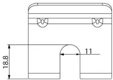
Technical drawing of a mechanical component with concentric curved layers and mounting brackets (no text or symbols)1 Cavallotto ferma sonda
Comando dedicato (FWEC10 - FWECSA - FWEC3A)
line
| Condition | Value [%] | |---|---| | set | 20 | | set+0.5°C | 20 | | set+3°C | MAX |» Riscaldamento
line
| Temperature | Value (%) | | :--- | :--- | | set-3°C | MAX | | set-0.5°C | 20 | | set | 20 |natural_image
Technical line drawing of a mechanical assembly with no visible text or symbols»Fig.3

natural_image
Pure technical diagram of a mechanical assembly with no text, numbers, or symbolsnatural_image
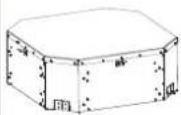
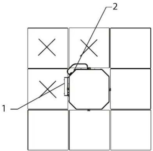
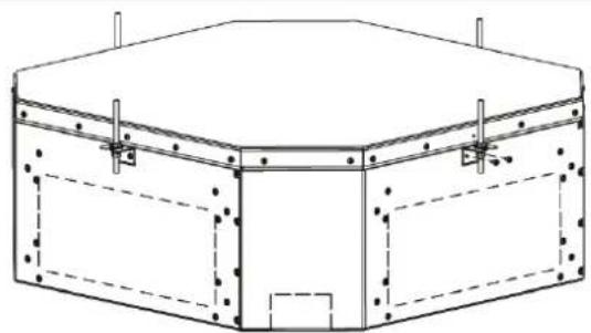
Technical line drawing of a hexagonal mechanical housing with mounting holes and dashed-line internal components (no text or symbols)» Fig.9 FWI-A02-03-04
» Fig.10 FWI-A06-07-08
natural_image
Technical line drawing of a rectangular electronic component or enclosure with mounting holes and internal structure (no text or symbols)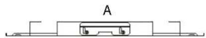
natural_image
Technical line drawing of a rectangular electronic component with mounting holes and internal structure (no text or symbols)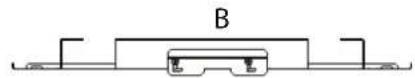
6.2 METTERE L'UNITÀ IN TENSIONE
natural_image
Technical line drawing of a mechanical component with no visible text or symbols1 Scarico condensa
»Fig.16
natural_image
Technical line drawing of a mechanical component with labeled parts (no text or symbols present)1 Scarico condensa
natural_image
Simple line drawing of a rectangular device with two side connectors and wheels (no text or symbols)» Fig.18 FWI-A 06-07-08

natural_image
Technical line drawing of a hexagonal mechanical or electronic device with four ports (no text or symbols)8.5 COLLEGAMENTO MANDATA ARIA IN LOCALI ATTIGUI
natural_image
Technical line drawing of a rectangular electronic device with mounting holes and a central panel (no text or symbols)||

natural_image
Technical line drawing of a mechanical housing or enclosure with internal components and mounting holes (no text or symbols)III
natural_image
Technical line drawing of a mechanical housing or enclosure with a circular component and labeled point D (no text or symbols beyond label)9 MANUTENZIONE
9.3 PULIZIA DEL FILTRO ARIA GRIGLIA FCND02A
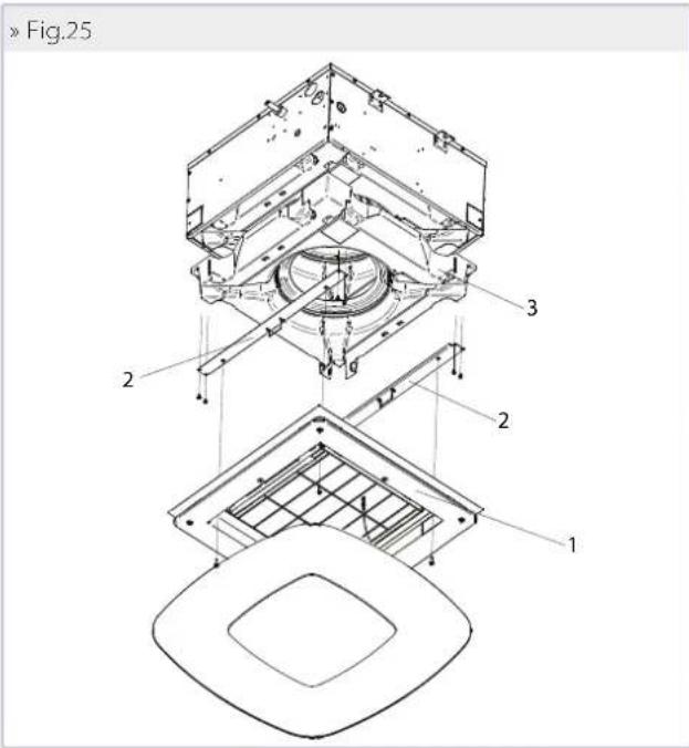
»Fig.25
9.7 LIVELLO ACQUA ANOMALO
10 RICERCA DEI GUASTI
Carefully read this manual.
Installation and maintenance should be carried out by technical personnel qualified for this type of machine, in compliance with current safety regulations.
When receiving the unit please check its state verifying if any damage occurred during the transport.
For installation and use of possible accessories please refer to the pertinent technical sheets.
The manual are subject to changes, in any times, without prior notice aimed at improving the product.
Identify the model of the FWI-A cassette fan coil following the indications on the packing container.
SAFETY SYMBOLS

Carefully read this manual.
Warning
Use personal protective equipment
USE APPROPRIATE PPE (GLOVES, PROTECTIVE GOGGLES)
WARNING: electrical and electronic products may not be mixed with unsorted household waste. Do NOT try to dismantle the system yourself: the system must be dismantled by an authorised installer and must comply with applicable legislation. Units must be treated at a specialized treatment facility for reuse, recycling, and recovery. By ensuring that this product is disposed of correctly, you will help to prevent potential negative consequences for the environment and human health. For more information, contact your installer or local authority.
DANGER: The unit may be used by children of at least 8 years of age and by persons with reduced physical, sensory, or mental capabilities, or who lack experience or the necessary knowledge, provided that they are supervised or after they have received instructions relating to the safe use of the unit and understand the inherent dangers. Children must not play with the unit. Cleaning and maintenance to be carried out by the user must not be performed by unsupervised children.
WARNING: Before performing any work on the unit, ensure it has been disconnected from the power supply.
WARNING: unit installation and start-up must be entrusted to competent personnel and performed in a workmanlike manner, in accordance with current regulations.
2 INTENDED USE
The manual are subject to changes, in any times, without prior notice aimed at improving the product.
DAIKIN will not accept any liability for damage or injury caused as a result of installation by non-qualified personnel; improper use or use in conditions not allowed by the manufacturer; failure to perform the maintenance prescribed in this manual; use of spare parts other than original factory parts.
Equipment designed for ambient air conditioning and intended for use in civil comfort applications.
INSTALLATION SITE
When choosing an installation site, you should observe the following rules:
— install the unit indoor only
— Do not install the unit in a room containing flammable, alkaline, acidic, oily, or very humid air, nor in one where water may be projected (e.g. laundry room). The components would be irreparably damaged.
— choose the most central position of the room.
— do not install the unit where excessively high heat-generating equipment is located
— make sure that in the chosen location nothing will obstruct the system and its maintenance (beams, insufficient suspended ceiling height, suspended ceiling panels that cannot
be removed, difficult access for maintenance, etc.).
— it is the customer's responsibility to provide safe access to the base unit, on the sides where there is an electrical box and water connections, to ensure the proper execution of routine and extraordinary maintenance operations. In case of installation in modular suspended ceilings, it is necessary to provide access to the panels shown in figures Installation FWI-A 02-03-04 and Installation FWI-A 06-07-08.
— the minimum installation space between the structural ceiling and the suspended ceiling is:
| Model Distance [mm] | |
| FWI-A 02-03-04 310 | |
| FWI-A 06-07-08 360 |
— the maximum dimensions of the opening to be made in the suspended ceiling to house the fan coil unit are as follows:
| Model MAX. dimensions [mm] | |
| FWI-A 02-03-04 690x690 | |
| FWI-A 06-07-08 820x820 |
— do not use or store petrol or other flammable liquids near the unit. It is very dangerous.
— do not install electrical equipment that is not protected with IPX1 degree of protection (protection against vertical water drop) underneath the unit.
— The manufacturer assumes no responsibility if safety and accident prevention regulations are not observed.
Note: the diffusion of air will not be as efficient if the room is more than 3 metres high.
» Installation FWI-A 02-03-04
1 Electric box
2 Water connections
» Installation FWI-A 06-07-08
1 Electric box
2 Water connections
OPERATING LIMITS
Thermal carrier fluid: water
Water temperature: 5^ C ÷ 80^ C
Air temperature: 5°C ÷ 43°C
Supply voltage: 230 V - 50 Hz
Maximum water pressure during operation: 10 bar
Relative humidity limit of the ambient air:RH < 75% not
condensing
3 UNIT DESCRIPTION
Comfort, low noise, and efficiency in perfect harmony!
The new series of hydronic cassette units FWI-A, with inverter-controlled permanent magnet EC motor, consists of six models (02-03-04-06-07-08) for 2-pipe systems and four models (02-04-06-08) for 4-pipe systems.
The engineering of the unit makes it possible to develop up to 5 kW in the cooling mode in a standard 600x600 mm modular suspended ceiling and over 10 kW in the 860x860 mm modularity, with exceptionally low noise levels in the phases for maintaining interior comfort.
The well-known advantages of EC motors are combined with GreenTech technology (in models 10, 20, and 30), which integrates the inverter directly into the fan drive assembly.
FWI-A leverages the entire FWEC3A, FWECSA and FWEC10 microprocessor controller platform that incorporate sophisticated adjustment logics based on air temperature, air humidity, and water temperature.
These benefits translate into greater accuracy in achieving and maintaining the desired comfort conditions through appropriate modulation of the fan speed as well as the reduction of noise emissions, which adapt to the actual thermal load.
Lastly, electricity consumption is reduced by up to 75% in comparison to conventional fixed-speed AC motors.
The suspended ceiling unit houses all the components, heat exchange coil, fan drive assembly, and condensate collection and drainage system. Its structure is designed for introducing fresh
air into the space, mixing it with recovered air, and distributing the treated air from the cassette unit to adjacent rooms.
Two tipes of intake and oulet air grilles:
FPAN Grill: ABS material, available in RAL9003 guarantee optimal integration into the suspended ceiling panels.
With easy access to air filter for cleaning operations.
The unit can be supplied complete with valves, including pressure-independent balancing and control valves, the use of which significantly reduces commissioning time.
FCND02A gille : design grille with Coandă effect: DIBOND material, thanks to Coandă effect, the air is expelled parallel to the ceiling, cooling the walls before mixing with the ambient air at the ground. In this way the operation will be optimized during the summer, ensuring more comfort for the occupants.
AVAILABLE VERSIONS
FWI0*ATN - Unit with one coil for 2-pipe systems
FWI0*AFN - Unit with one coil for 4-pipe systems
Accessories supplied with the unit
— Auxiliary water drip tray;
— Installation and use manual;
— Brackets for securing the unit.
MAINCOMPONENTS
Structure
Made of galvanised steel sheet with internal polyurethane foam coating and external fl ocked PES to guarantee heat and sound insulation. Fresh air can be introduced into the room directly through the unit due to the provision of connections for neutral or mixed introduction. Accessories are available for connection to ducts. There are systems on the unit for anchoring it to the ceiling. The electrical wiring is housed in a containment box and is easily accessible from the side for easy connection.
Airfilter
Honey-comb polypropylene washable air filter, easily removable for maintenance operations.
Heatexchanger
Copper pipe and high efficiency aluminium fins secured to the pipe by mechanical expansion. With at least two rows in the models for 2-pipe systems, it is available in the 2+1 configuration in the models for 4-pipe systems. The coil comes complete with manual air vent valves. On request, valves can be connected to the coil to regulate and balance the operation of the unit.
Fan drive assembly
Inverter-controlled permanent magnet EC electric motor (integrated in the GreenTech models) directly connected to a centrifugal fan with backward-curving blades with profi le optimised for stable operation at all speeds.
Condensate collection system
Located under the heat exchanger, the main drip tray is made of polystyrene and is inserted inside the profi les optimised for the distribution of air in the room. The supply is completed by the auxiliary water drip tray for the collection of condensate from the regulating valves.
Condensate discharge system
The condensate drainage pump, with built-in check valve, can lift the condensate up to 0.9 m from the exit point from the unit. The operation of the pump is controlled by a float switch with three levels of action that activate it and stop it during normal operation. If the critical water level inside the main drip tray is exceeded, an alarm signal closes the control valves, stopping the flow of water inside the exchanger.
FPANGrille
It is square shaped for the intake and diffusion of air in the space, and it is made of ABS, colour RAL9003 or RAL9010. The air intake louvre can be opened for access to the air fi liter. Air is diff used in the space through the 4 sides, each of which is equipped with an adjustable fi n with suitable thermal insulation.
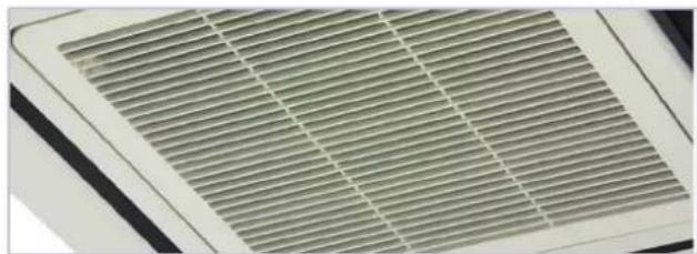
natural_image
Close-up of a ventilation grille with uniform horizontal slats (no text or symbols visible)FCND02A grille: design grille with Coandă eff ect
It is square shaped with circle intake hole, it is made in DIBOND material. The intake grille is opened for access to the air fi liter. Air is diff used in the space through the conveyors in 4 sides and takes advantage of the fluid dynamic Coandă effect.
Thanks to Coandă effect, the air is expelled parallel to the ceiling, cooling the walls before mixing with the ambient air at the ground. In this way the operation will be optimized during the summer, ensuring more comfort for the occupants.
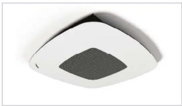
natural_image
Close-up of a white and gray ceiling-mounted air conditioner unit with a mesh grille (no text or symbols visible)ACCESSORIES
Electronic microprocessor control panels with display
| FWTOUCH | 2.8" touch screen user interface for FWECSA control | |
| FWECSAP | Circuit board for FWECSA control | |
| FWECSAC | User interface with display for FWECSA controller | |
| FWEC3A | Microprocessor control with display FWECS3A | |
| FWHSKA | Humidity sensor for FWECS3A, FWECSA | |
| FWTSKA | Water sensor for FWECS3A and FWECSA controllers |
Electronic microprocessor control panels
| FWEC10 | Electronic controller for EC fan equipped with inverter and ON/OFF valves 230 V |
Valves
 | E2C2PIC/PRP E4C2PIC/PRP | PRESSURE-INDEPENDENT 2-way valves for models with 1 or 2 coils |
 | E2C2 | 2-way valve, ON/OFF or MODULATING actuator, 230 V or 24 V power supply, hydraulic kit, for model with 1 or 2 heat exchangers |
 | E2C3 | 3-way valve, ON/OFF or MODULATING actuator, 230 V or 24 V power supply, hydraulic kit, for model with 1 or 2 heat exchangers |
| Plenum, air intake modules, air inlet and outlet connectors and cabinets | ||
 | SPFAI1A/ SPFAI2A | Spigot for introduction of mixed renewal air |
 | PPAI02A/06 Air outlet plenum | |
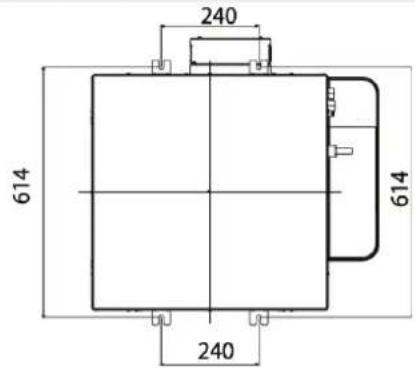
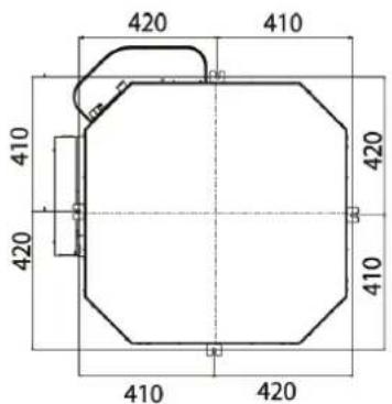
4 DIMENSIONS
Figures on page p. 163 - p. 161 show the dimensions of FWI-A and the positions of the water connections.
5 INSTALLATION
WARNING: It is mandatory to install the 3-way (or 2-way) valve accessory in order to avoid the circulation of cold water in the exchanger if the unit is not operated for long periods of time, with the fan off. Install the auxiliary water drip tray, provided together with the base unit, in order to prevent valve kits from dripping.
For each unit an (IL) switch should be mounted on the power supply, with opening contacts at a distance of at least 3 mm and a suitable protection fuse (F).
WARNING: before carrying out any operation, check that the voltage and frequency of the unit correspond exactly to those of the main power supply.
WARNING: Install the unit, circuit breaker (IL) and/or any remote controls in a place out of reach of persons who may be taking a bath or shower.
WARNING: the EMC filters connected to frequency converters (inverters) can create leakage currents toward ground (in order to make the unit EMC compliant, by reducing conducted emissions on power supply line). Depending on installation site, this can force the cut out of the differential safety switch. It is recommended to install a separate differential safety switch, only for the EC unit, with an adjustable threshold for the cut out current.
WARNING: keep the unit's grille in its original packaging until final assembly.
RECOMMENDED: to ensure optimal comfort (homogeneous air temperature in the room), it is recommended not to exceed a heat exchanger water inlet temperature of 55 °C.
WARNING: during a shutdown for installation, in the event of a connection to a fresh air intake or an ambient temperature close to 0 °C, there is a risk of the pipes freezing. Provide drainage for the water circuit.
WARNING: Install the unit without providing slopes; for a correct condensate drainage there is a slope in the condensate drip tray inside the unit.
INSTALLATION REQUIREMENTS
The fan coils should be installed in a position where the room can be heated or cooled evenly, on ceilings able to support their weight. Store the unit in its packaging until you are ready to install it.
For installation and use of accessories, please refer to the relative technical sheets.
Install any remote control panel in an easily accessible position allowing the user to set the functions while ensuring an accurate reading of the ambient temperature, if provided.
Avoid therefore:
— positions directly exposed to sunlight;
— positions exposed to direct currents of warm or cold air
—placing obstacles that impede an accurate temperature reading
During continuous winter operation, to avoid problems relating to the regulation of the unit, it is recommend to use remote controls supplied with a probe for detecting the air temperature.
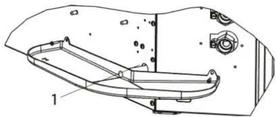
NB: The water sensor, where present, must be mounted in the appropriate trap on the valve kit, on the INLET pipe.
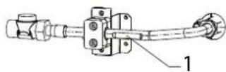
1 Water sensor holder
— If a valve kit other than the one suggested is used, it is necessary to install the sensor on the INLET pipe, by means of the special copper socket filled with conductive paste.
— Lastly, the sensor must be properly isolated to ensure that it reads the water temperature correctly.
NB: The air and humidity sensors, where present, must be attached in the appropriate section located in the intake area of the base unit. Sensor retainer and relative fixing screws are supplied with unit.

natural_image
Technical line drawing of a mechanical component with layered structure (no text or symbols)1 Sensor retainer
Make the plumbing connections to the heat exchanger and, where the cooling function is to be used, to the condensate drainage outlet.
WARNING:
In normal operation, particularly with the fan at minimum speed and ambient air with high relative humidity, condensation may form on the air outlet and on some external parts of the unit.
To avoid such issues while always remaining within the operating limits envisaged for the unit, it is necessary to limit the inlet temperature of the water inside the heat exchanger. In particular, the difference between the air dew point ( T_A, D_P ) and the inlet water temperature ( T_W ) must NOT exceed 14°C, according to the following relationship: TW>TA, DP-14°C
Example: in the case of ambient air at 25^ C with 75% relative humidity, the dew point temperature is about 20^ C and therefore the inlet temperature of the water in the battery must be greater then:
— 20-14 = 6 °C in order to avoid condensation on a fancoil equipped with a valve.
| Fan coil with valve | ||||||||
| Air temperature dry bulb (°C) | ||||||||
| 21 23 25 27 29 31 33 | ||||||||
| Relative humidity % | 40 55 55 55 55 | |||||||
| 50 55 55 56 8 | ||||||||
| 60 55 55 79 11 | ||||||||
| 70 55 68 91 13 | ||||||||
| 80 56 810 1214 16 | ||||||||
| 90 68 1012 1416 18 | ||||||||
If the valves are not installed, there could be abundant condensation, especially if the unit is not operated for long periods of time.
During wintertime periods of quiescence, drain water from the system, to prevent ice from forming. If anti-freeze solutions are used, check for their freezing point using the table below.
| % Glycol by weight | Freezing temperature (°C) | Capacity adjustment | Pressure drop adjustment |
| 0-0 1,00 1,00 | |||
| 10-40,97 1,05 | |||
| 20-100,92 1,10 | |||
| 30-160,87 1,15 | |||
| 40-240,82 1,20 |
Electrical connections
Make the electrical connections whilst the power supply is disconnected, in accordance with current safety regulations, carefully following the wiring diagram and its legend.
Check that the mains electricity supply is compatible with the voltage shown on the unit rating plate.
The electrical connections indicated must be made by the installer.
For each fan coil a switch (IL) should be mounted on the power supply, with opening contacts at a distance of at least 3 mm and a suitable protection fuse (F).
For the electrical connections of the controls, follow the diagrams in the figures from: p. 168.
WARNING: The power supply to the pump-float switch device must never be interrupted.
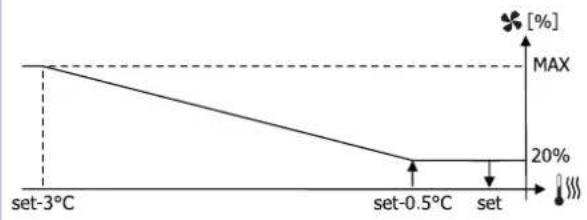
Control dedicated (FWEC10 - FWECSA - FWEC3A)
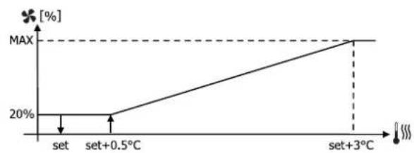
Controls implement a logic that makes it possible to set a fixed speed shown in the figure with analog signal 3, 6, 8 V or automatic speed modulation, that takes full advantage of the EC motor. The automatic logic varies the analog signal to the motor between 2 and 10 V, based on the distance from the set-point, in order to accelerate the implementation phases and then settle at a very low holding speed.
»Cooling
line
| Condition | Value [%] | |---|---| | set | 20 | | set+0.5°C | 20 | | set+3°C | MAX |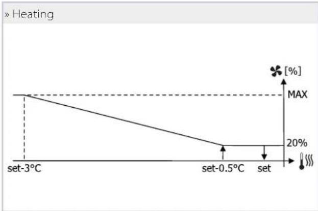
line
| Temperature Set | Percentage [%] | | ---------------- | -------------- | | set-3°C | MAX | | set-0.5°C | 20% | | set | 20% |Hydraulic connections
| Unit | Exchanger connection | |
| FWI02ATN, FWI03ATN, FWI-04ATN (2 pipes) | 1/2" gas F | |
| FWI06ATN, FWI07ATN, FWI-08ATN (2 pipes) | 3/4" gas F | |
| Cooling Heating | ||
| FWI02AFN, FWI04AFN (4 pipes) | 1/2" gas F | 1/2" gas F |
| FWI06AFN, FWI08AFN (4 pipes) | 3/4" gas F | 1/2" gas F |
To optimise performance, it is advisable to make the following connections on the exchanger:
— Unit outlet: connection below.
— Unit return: connection above.
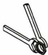
WARNING: While making the connections, hold the water connections of the unit tightly in place with a hexagonal wrench or make sure that they do not rotate, in order to prevent the pipes inside the unit from being damaged.
— Carefully insulate the inlet and outlet water pipes as well as the devices installed in the network (on/off valves...). Use a material that is suitable for the operating conditions and water temperature.
— Bleed air from the exchanger by means of the air vent valves located next to the water connections of the coil. Depending on the installation, it may be necessary to place other vent valves on the hydraulic system.
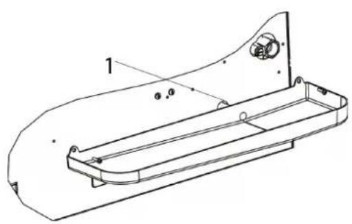
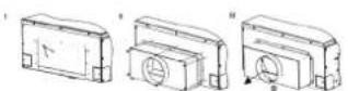
Condensate drain connection
Connect a rigid PVC pipe to the end of the hose and secure it with a clamp
Correctly insulate the pipe with polyethylene foam.
— Be careful of the risk of freezing in winter in suspended ceilings.
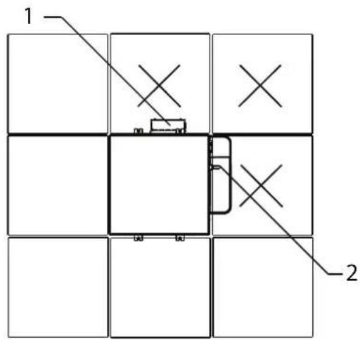
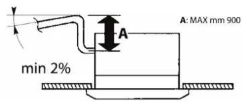
— If necessary, the condensate pipe can be routed immediately after the unit's outlet. Maximum height: 900 mm (FIGURE 1).
— Make sure that the drainpipe has a slight slope in the
direction of flow and that it does not form a siphon (FIGURE 1).
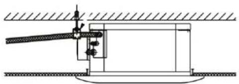
— The piping must have several supports (FIGURE 2).
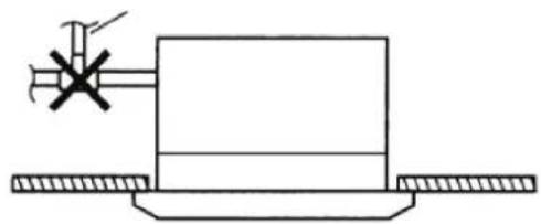
— Do not install an air vent (FIGURE 3) in the wrong position.
»Fig.1
»Fig.2
natural_image
Technical line drawing of a mechanical assembly with no visible text or symbols»Fig.3
natural_image
Pure mechanical diagram showing a rectangular block with a cross mark and a tool, mounted on a base with two side supports (no text or symbols)DIMENSIONAL UNIT ASSEMBLY
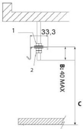
— Use the dimensional drawings to determine the position of the suspension rods (Fig.4 FWI-A 02-03-04) (Fig.5 FWI-A 06-07-08)
— Position the suspension rods (not supplied) in place.
— Attach the supplied brackets (Fig.6) to the suspension rods (Fig.7). The length of the suspension rods depends on the space between the suspended ceiling and the structural ceiling.
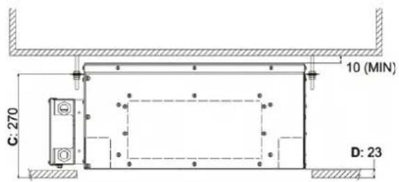
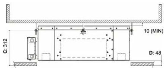
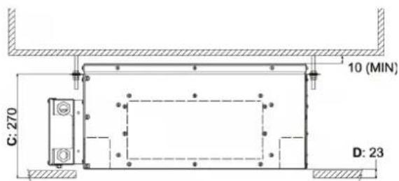
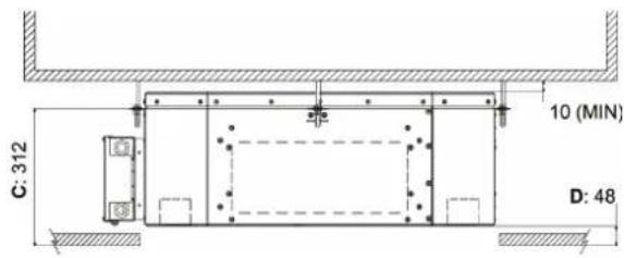
— The distance C (Fig.7) must be:
| Model | C- Bracket distance to the false ceiling |
| FWI-A 02-03-04 270 | |
| FWI-A 06-07-08 312 |
— Pay attention to the excess length B of the suspension rod (Fig.7): it may interfere with the unit's electrical box.
— Place the fan coil unit in the suspended ceiling, orienting the side with the water connections in the most appropriate
position, using the hooks on the brackets to provide quick temporary installation.
— Then attach the unit to the threaded bars with the screws provided and check that it is level (Fig.8)
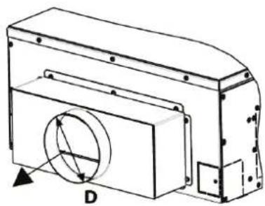
— Adjust the distance between the unit and suspended ceiling D (Fig.9 FWI-A 02-03-04 and Fig.10 FWI-A 06-07-08) using the nuts of the suspension rods:
| Model | D - Distance from unit to false ceiling |
| FWI-A 02-03-04 23 | |
| FWI-A 06-07-08 48 |
— Make sure that the unit does not touch the ceiling: contact may cause noise.
— Insulate the brackets (Fig.6) fixed on the unit with the insulation supplied.
» Fig.4 FWI-A 02-03-04
» Fig.5 FWI-A 06-07-08
» Fig.6
»Fig.7
- Nut + washer
- Washer + nut + lock nut
»Fig.8
natural_image
Technical line drawing of a hexagonal mechanical housing with mounting flanges and internal compartments (no text or symbols)» Fig.9 FWI-A02-03-04
» Fig.10 FWI-A06-07-08
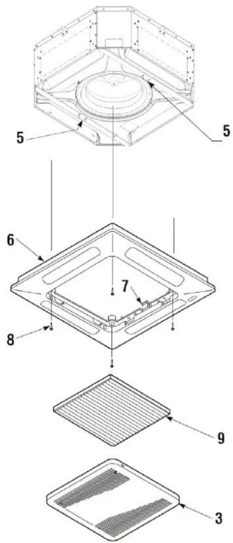
Front panel/FPAN grille assembly
The front panel/grille, available in RAL9003 versions, is delivered in a separate cardboard box:
— FPAN02 for models FWI-A 02-03-04
— FPAN06 for models FWI-A 06-07-08
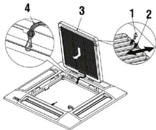
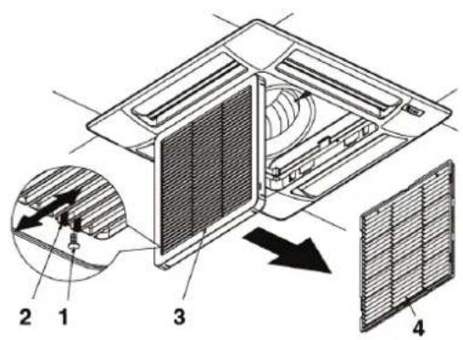
Before installing the front panel: (Fig.11)
— Remove the screws (1) securing the retainers (2) on each side (remember to put these screws back in place after installation).
— To open the grille (3), move the two retainers (2) in the direction of the arrow.
— Open the grille (3) by 45°.
— Detach the control panel's safety cable (4) (remember to attach it again after installation).
— Lift the grille to remove it from the control panel.
»Fig.11
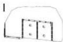
To install the front panel: (Fig.12)
— Turn the two locking clips (5) downwards.
— Attach the control panel of the panel (6) to the unit by means of the two hooks (7), matching them to the locking clips (5).
— Check the exact position of the panel's control panel in relation to the suspended ceiling. Adjust the position of the indoor unit as necessary.
— Attach the panel's control panel to the unit using the special screws and washers (8) provided.
— Put the grille (3) in place, making sure that the filter (9) is correctly positioned.
— Hook the safety cable to the control panel, close the grille, and put the screws securing the retainers (2) back in place.
»Fig.12
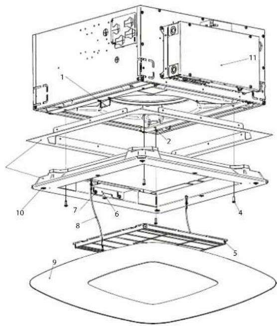
Front panel/grille FCND02A assembly
The front panel/grille, available for FWI 02-03-04 versions, is delivered in a separate cardboard box:
To install the panel (Fig.13):
— Turn the two locking clips (1) downwards.
— Attach the panel body (3) with appropriate screws (4) at the inserts (2) already present on it.
— For the correct fixing of panel group (3) align one of the sides with filter fixing bracket (6) to the sides with electrical box (11).
— To install the filter, unscrew slightly the fixing screws (7) of support brackets (6).
— From position (A), move the two brackets (6) horizontally first and then vertically along "L" guides, to move the screws (7) to position (B).
— Pass the filter through the cleared area by the movement of brackets and block it by reversing the procedure to the point above, then replace the screws (7) in position (A) and tighten them.
— Place the covering panel (9) hooking up safety cables first (8) to the clip (1) and then join the panel with unit (3) through magnets (10) on 4 sides.
»Fig.13
natural_image
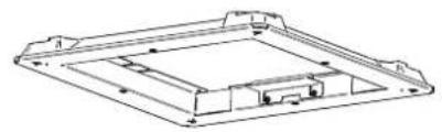
Technical line drawing of a mechanical housing or enclosure with mounting brackets and internal components (no text or symbols)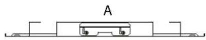
natural_image
Technical line drawing of a rectangular electronic component with mounting holes and internal structure (no text or symbols)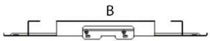
6 CHECKS BEFORE STARTUP
6.1 PRELIMINARY CHECKS
Make sure:
— make sure that the power cable is not damaged, if it is damaged must be replaced by the manufacturer or its technical assistance service or in any case by a person with a similar qualification, in order to prevent any risk,
— that the unit is stable and perfectly level,
— that the electrical cables are well tightened on their terminal blocks (if they are not tightened properly, the terminals may cause the terminal block to overheat),
— that the electrical cables are properly insulated from any sheet metal or metal parts that could damage them,
— that the unit is well earthed,
— that no tools or any other foreign objects have been left in the unit,
— that the filter is properly installed,
— that the coil is clean,
— that the hydraulic fittings are properly tightened,
— that the condensate drain is properly connected and not obstructed,
— that the condensate drain pan is clean,
— that the drainage pipes are securely fastened.
6.2 SWITCH ON THE UNIT
— Using an isolation and protection device.
— Start the unit using the controller.
— Start-up should be carried out at the maximum operating speed.
— A running in period of 100 hours is necessary to eliminate all initial mechanical friction of the motor.
6.3 FILL THE WATER CIRCUIT
— Ensure operation of the motor-driven valve by operating it via the remote control.
— Check that all the connections are watertight.
— Check the operation of the condensate drainage pump by pouring a little water into the auxiliary water drip tray located under the valve.
— Check that there is no water backflow when the pump is stopped.
— Purge the air from the cassette's heat exchanger.
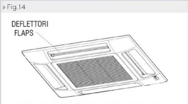
6.4 ADJUSTING THE AIR FLOW (FPAN ONLY)
You can adjust the air flow direction using the 4 fl aps on the front panel.
Choose the position according to the operating mode and the recommended inclination: the position of the flaps must be adjusted manually. (Fig.14 and Fig.14.1)
»Fig.14.1
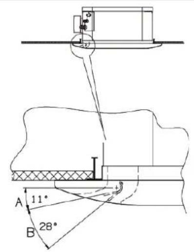
A. Cooling and dehumidification zone
B. For the heating of zones
7USE
This unit is intended for the air conditioning of rooms for the maximum well-being of people. Designed for room air conditioning and intended for residential comfort applications.
To use the fan coil refer to the instructions on the control panel available as accessory.

ATTENZIONE: For safety reason, do not introduce your fingers or other pointed objects in the air outlet grilles.

DANGER: The unit may be used by children of at least 8
years of age and by persons with reduced physical, sensory, or mental capabilities, or who lack experience or the necessary knowledge, provided that they are supervised or after they have received instructions relating to the safe use of the unit and understand the inherent dangers. Children must not play with the unit. Cleaning and maintenance to be carried out by the user must not be performed by unsupervised children.
8ACCESSORIES
8.1 2- OR 3-WAY MOTOR-DRIVEN VALVE KITS

WARNING: The installation of a valve kit on the fan coil unit is mandatory FWI-A.
The kit is made up of:
— Brass 2- or 3-way valve with 4 connections with built-in bypass, maximum operating pressure 16 bar.
— Electrothermal actuator with 230 V or 24 V power supply, ON/OFF (or modulating) function, total opening time 3 minutes.
— Hydraulic kit with O-ring for connection with the exchanger and paper gasket for connection with the valve
— Brackets for fastening the hydraulic kit on the side of the unit in order to ensure stability during transport if the valves are already installed.

NOTE: for units FWI-A 02-03-04 it is necessary to install the 3-way valves inclined so as to comply with the space constraint regarding the height of the base unit.
The valve kits are shown in the figures from page: p. 176.
Pressure drops of the valve/hydraulic kit assembly are calculated using the following formula:
$$ \Delta P _ {W} = \left(Q _ {W} / K _ {V}\right) ^ {2} $$
Where:
P_w pressure drop in bar
Q_w water flow rate in m^3/h
Kv water flow rate coefficient of the valve obtained from the table
| Unit Valve type Connection Kvs straight Kvs by-pass | |||||||
| FW102ATN, FW103ATN, FW104ATN (2 pipes) 3-way 3/4" M 2,5 1,6 | |||||||
| FW106ATN, FW107ATN, FW108ATN (2 pipes) 3-way 3/4" M 4 1,6 | |||||||
| Cooling Heating | |||||||
| Unit Valve type Connection KVS direct way Kvs by-pass Connection KVS direct way Kvs by-pass | |||||||
| FW102AFN, FW104AFN (4 pipes) | 3-way | 3/4"M | 2,5 | 1,6 | 3/4"M | 2,5 | 1,6 |
| FW106AFN, FW108AFN (4 pipes) | 3-way | 3/4"M | 4 | 1,6 | 3/4"M | 2,5 | 1,6 |
| Unit Valve type Connection | KVS | ||||||
| FW102ATN, FW103ATN, FW104ATN (2 pipes) | 2-way | 3/4"M | 2,8 | ||||
| FW106ATN, FW107ATN, FW108ATN (2 pipes) | 2-way | 3/4"M | 4 | ||||
| Cooling | Heating | ||||||
| Unit | Valve type | Connection | KVS | Connection | KVS | ||
| FW102AFN, FW104AFN (4 pipes) | 2-way | 3/4"M | 2,8 | 3/4"M | 2,8 | ||
| FW106AFN, FW108AFN (4 pipes) | 2-way | 3/4"M | 4 | 3/4"M | 2,8 | ||
8.2 PRESSURE-INDEPENDENT MOTOR-DRIVEN 2-WAY VALVE KIT

WARNING: The installation of a valve kit on the fan coil unit is mandatory FWI-A.
The pressure-independent 2-way valve kit consists of:
— 2-way valve with maximum operating pressure of 16 bar.
— Electrothermal actuator with 230 V or 24 V power supply, ON/OFF (or modulating) function, total opening time 3 minutes.
— Hydraulic kit with O-ring for connection with the exchanger and paper gasket for connection with the valve.
— Brackets for fastening the hydraulic kit on the side of the unit in order to ensure stability during transport if the valves are already installed.
The valve kits are shown in the figures on page: p. 180, p. 181, p. 180, and p. 181.
| Unit | Valve type | Connection | p min [kPa] | ||
| FW102AFN, FW103ATN, FW104ATN (2 pipes) | 2-way | 3/4"M | 3.2 | ||
| FW106ATN, FW107ATN, FW108ATN (2 pipes) | 2-way | 1 1/4"M | 20 | ||
| Cooling | Heating | ||||
| Unit | Valve type | Connection | p min [kPa] | Connection | p min [kPa] |
| FW102AFN, FW104AFN (4 pipes) | 2-way | 3/4"M | 16 | 3/4"M | 16 |
| FW106AFN, FW108AFN (4 pipes) | 2-way | 1 1/4"M | 20 | 1"M | 16 |
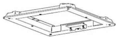
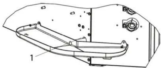
8.3 AUXILIARY WATER DRIP TRAY FOR COLLECTING CONDENSATE FROM THE CONTROL VALVES
The auxiliary water drip tray is supplied with the base unit together with two fastening screws.
Its function is to collect the condensate generated by the control valves and to convey it inside the main condensate drip tray of the unit. (Fig.15, Fig.16)
»Fig.15
natural_image
Technical line drawing of a mechanical component with labeled parts (no text or symbols beyond basic labels)1 Condensate discharge
»Fig.16
natural_image
Technical line drawing of a mechanical component with labeled parts (no text or symbols present)1 Condensate discharge
WARNING: The installation of the auxiliary water drip tray is mandatory.
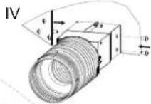
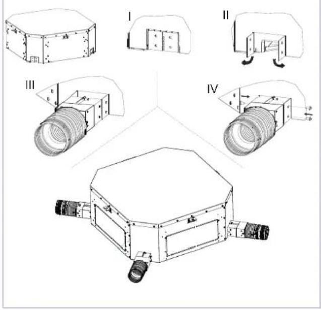
8.4 CONNECTION FOR INTAKE OF FRESH AIR TO BE TREATED
The units are equipped with 3 fresh air inlets, positioned in the corners. This air mixes with the air drawn in from the indoor environment and is then treated by the heat exchanger. (Fig.17 - Fig.18)
— The SPFAI1A (FWI-A 02-03-04) and SPFAI2A (FWI-A 06-07-08) accessory is available: a fi tting for ∅100 pipe to be connected to the inlets located on the unit.
— It is necessary to filter the fresh air before introducing it in the unit, making sure that its temperature is not too low.
— To avoid operating and noise-related problems, the fresh air flow rate is limited to 20% of the unit's air flow at average speed, with a maximum of 110 m³/h for each intake.
WARNING: It is necessary to prevent the intake of dust and impurities that could foul the unit's exchanger.
» Fig. 17 FWI-A 02-03-04
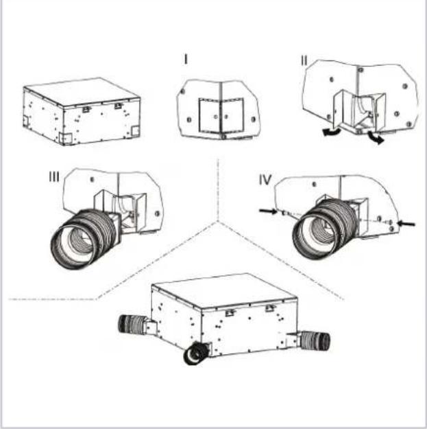
» Fig.18 FWI-A 06-07-08
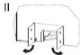
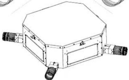
8.5 CONNECTION FOR OUTLET OF AIR IN ADJACENT ROOMS
The units are equipped with 2 rectangular air outlets for connection to separate distribution ducts.
— These outlets are located on the sides not occupied by the electrical box and water connections.
— The PPAI02A/06 accessory is available: a plenum to connect the rectangular outlets located on the unit to the round distribution ducts with diameter D:
| Model D | |
| 02-03-04 150 | |
| 40-50-60 180 |
WARNING: The air ducts from the fan coil unit must be thermally insulated to prevent the formation of surface condensation.
» PPA102A/06 - Air outlet
For safety reasons, before carrying out any maintenance or cleaning jobs, turn off the unit by moving the fan speed selector to "OFF" and putting off the main switch 0 (OFF).
Any work must be carried out by personnel qualified and authorised to work on this type of unit.

DANGER!
maintenance: some metal parts may cause injuries; wear protective gloves.
The material must undergo maintenance in order to retain its characteristics over time. Lack of maintenance may have the effect of voiding the product warranty. The operations consist of cleaning the air fi iter, the internal and external exchangers, the cabinet, and cleaning and protecting the condensate drip trays. Odour treatment and disinfection of the surfaces and spaces also contribute to the healthiness of the air breathed by users.
Whenever starting up the unit after it has not been used for a long time, check that there is no air in the heat exchanger.
Before the period of operation in the cooling mode, check that condensate is properly drained.
Adequate periodic maintenance will ensure save both energy and cost savings.
9.1 CLEANING THE AIR FILTER GRILLE FPAN
Clean the air filter at least once a month and in any case at the start of the period of use (before the heating and the air conditioning season).
For fi Iter cleaning, proceed as follows (Fig.21):
- Before performing any work on the unit, disconnect it from the power supply.
- Remove the screws (1) securing the retainers (2) on each side.
- To open the grille (3), push on the two retainers (2) in the direction of the arrow.
- Open the grille (3) downwards.
- Remove the filter (4) from the grille.
- Use a vacuum cleaner to remove dust. If dust is glued to the filter, remove it with clean or soapy water, rinse the filter with clean water and dry it.
- Put the fi Iter back into its place in the grille, close the grille, moving the two retainers outwards, then put the screws securing the retainers back in place.
It is recommended to replace the air fi Iter once a year, using an original replacement fi Iter; the indoor unit model can be found on the identification plate located on the tank inside the unit, behind the air fi Iter.
»Fig.21
9.2 CLEANING THE AIR INTAKE GRILLE FPAN
The grille can be removed for cleaning. (Fig.22)
— After opening the grille (5), detach the safety cable (6) of the control panel (7) (remember to attach it again after maintenance and cleaning).
— Lift the grille and pull it towards you to release the two hinges
— Clean the grille gently using a soft sponge, then dry well. A neutral detergent can be used to remove difficult residues. Rinse well with water, then dry.
— Never use harsh chemical solvents.
— Do not use excessively hot water to clean the unit.
»Fig.22
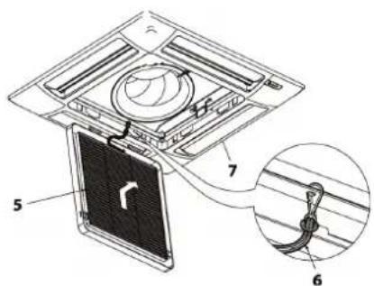
9.3 CLEANING THE AIR FILTER FCND02A GRILLE
Clean the air fi Iter at least once a month and in any case at the start of the period of use (before the heating and the air conditioning season).
For fi Iter cleaning, proceed as follows (Fig.23):
- Before performing any work on the unit, disconnect it from the power supply.
- Remove the magnet covering panel (1) pull down.
- Remove one of the two safety cables (2) to have free access to the filter.
-
Unscrew slightly the fixing screws (3) of support brackets (4).
-
From position (A) fig., move the two brackets (4) horizontally first and then vertically along "L" guides, to move the screws (3) to position (B).
- Remove the air filter (5) pulling out it.
- Use a vacuum cleaner to remove dust. If dust is glued to the filter, remove it with clean or soapy water, rinse the filter with clean water and dry it.
- Put the grille (5) back in place the brackets (4) in position (A) of fig. 32 and tighten screws again (3).
It is recommended to replace the air filter once a year, using an original replacement filter; the indoor unit model can be found on the identification plate located on the tank inside the unit, behind the air filter.
» Fig.23
9.4 CLEANING OF FCND02A GRILL COVER PANEL
— Use a soft and dry cloth.
— Never pour liquids onto the unit, as this could cause electrical discharges and damage the internal components.
— Never use harsh chemical solvents.
WARNING: NEVER USE ABRASIVE TOOLS of any kind. Failure to follow this instruction may result in irreversible damage to the surface of the graphics.
9.5 ELECTRIC CONTROL BOARD
Once a year, check that the electrical wires are properly tightened on their terminal blocks.
9.6 ADDITIONAL MAINTENANCE
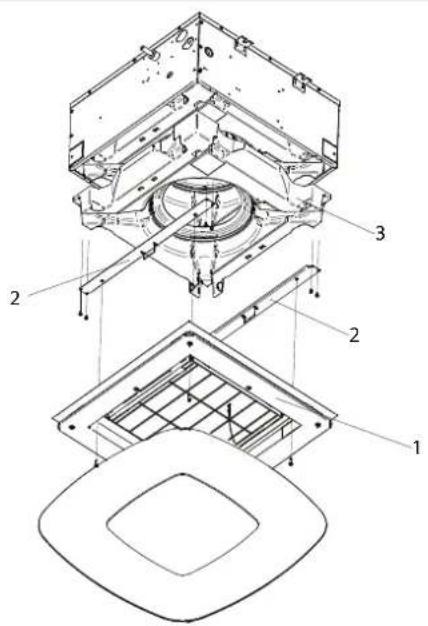
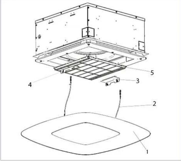
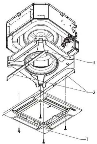
Inspecting, cleaning, or replacing internal components requires the removal of the main condensate tank.
Tank removal (Fig.24 and Fig.25):
— Remove the air intake grille (for standard grille); Remove the DIBOND cover panel pull down it and separate from the unit (for FCND02A grille).
— Empty the condensate remaining in the tank into a bucket by means of a pump through the condensate drain opening
of the auxiliary water drip tray (Fig.15 and Fig.16).
— Remove the front panel assembly (panel assembly) (1) by unscrewing the four fastening screws. Remove the support plates (2) of the tank (3) by removing the screws.
— Remove the tank, handling it with care.
— Clean the inside of the tank.
— Check that the heat exchanger is clean. If needed, use a vacuum cleaner with a rubber tip to remove dust being careful not to damage the fins.
Reinstallation of the tank:
— Put the tank (3) back in place with its supporting plates (2) and tighten the fastening screws.
— Put the front panel (1) back in place using the two tank plate clips to keep it suspended on the unit.
— Tighten the fastening screws.
— Put the grille back in place together with the air filter.
— Hook the grille's safety cable to the appropriate supports.
— Close the grille and put back the retainers fastening screws (for standard grille), Put back tha cover panel in original position. (for FCND02A grille).
»Fig.24
9.7 ABNORMAL WATER LEVEL
In case of abnormal backflow of water into the condensate tank (due to a faulty pump, a dirty tank, a plugged drain pipe, etc.), a safety contact (float switch) closes the control valves.
10 TROUBLESHOOTING
If the unit is not working properly, before calling a service engineer carry out the checks indicated in the table below.
If the problem cannot be solved, contact your dealer or the nearest service centre.
| PROBLEM CAUSE SOLUTION | ||
| The unit falls to work | No power supply Restore the power supply | |
| The automatic safety cutout has tripped Call a service centre for assistance | ||
| The on/off switch is on Start the unit by moving the switch to I | ||
| The unit provides insufficient cooling or heating | The air filter is dirty or clogged Clean the air filter | |
| The heat exchanger is dirty Call the installer for assistance | ||
| An obstacle is obstructing the air intake or outlet Remove the obstacle | ||
| Air is trapped inside the heat exchanger Call the installer for assistance | ||
| There are open windows and/or doors Close windows and/or doors | ||
| The minimum speed has been selected Select medium or maximum speed | ||
| The unit “leaks” water | The unit has not been installed with the correct inclination Call the installer for assistance | |
| The drainage outlet is clogged | Call the installer for assistance | |
| The pump is blocked | Call the installer for assistance | |
11 RATED TECHNICAL DATA
» Rated technical data FWI-A - 2 pipes
| FWI-A 02 03 04 | ||||||||||||||
| min med | max min med | max min med max | ||||||||||||
| Speed | 1 2 3 4 1 | 2 3 4 1 2 3 4 | ||||||||||||
| Control voltage (E) V | 2,00 3,50 | 4,50 6,00 | 2,00 4,00 | 5,50 8,00 2,00 4,00 | 6,50 10,0 | |||||||||
| Total cooling capacity (1)(E) kW | 1,33 1,93 | 2,24 2,63 | 1,49 2,68 | 3,40 4,39 | 1,54 2,76 | 3,95 5,23 | ||||||||
| Sensible cooling capacity (1)(E) kW | 0,99 1,51 | 1,81 2,20 | 1,03 1,94 | 2,54 3,41 | 1,05 1,98 | 2,96 4,11 | ||||||||
| FCEER class | (E) | A | ||||||||||||
| Water flow | (1) | l/h | 229 | 331 | 385 | 452 | 256 | 460 | 584 | 754 | 264 | 473 | 678 | 898 |
| Water pressure drop | (1)(E) kPa | 2 | 4 | 5 | 7 | 3 | 10 | 15 | 23 | 3 | 9 | 18 | 29 | |
| Heating capacity | (2)(E) kW | 1,49 2,27 | 2,70 3,25 | 1,42 2,69 | 3,48 4,58 | 1,47 2,77 | 4,09 5,55 | |||||||
| FCCOP class | (E) | A | B | B | ||||||||||
| Water flow | (2) | l/h | 258 | 395 | 470 | 565 | 248 | 468 | 605 | 797 | 255 | 481 | 711 | 965 |
| Water pressure drop | (2)(E) kPa | 2 | 5 | 6 | 9 | 3 | 8 | 13 | 21 | 3 | 8 | 16 | 27 | |
| Rated air flow | m^3/h | 212 | 397 | 454 | 583 | 187 | 397 | 551 | 796 | 190 | 397 | 650 | 980 | |
| Power input | (E) | W | 7 | 7 | 10 | 18 | 7 | 9 | 15 | 37 | 7 | 9 | 22 | 67 |
| Total sound power level | (3)(E) dB(A) | 28 | 35 | 40 | 48 | 28 | 37 | 44 | 54 | 29 | 38 | 49 | 61 | |
| Water content - standard coil | dm^3 | 1,14 | 1,63 | 1,63 | ||||||||||
| Cross-section area of power cables | (4) | mm^2 | 1,00 | 1,00 | 1,00 | |||||||||
| Power supply cable type | N07V-K | |||||||||||||
| Safety fuse F | A | 2 | 2 | 2 | ||||||||||
| Fuses type | gG | |||||||||||||
| FWI-A 06 07 08 | ||||||||||||||
| min med max | min med max min med max | |||||||||||||
| Speed | 123412341234 | |||||||||||||
| Control voltage (E) V | 2,003,005,0010,02,003,005,008,002,004,006,5010,0 | |||||||||||||
| Total cooling capacity (1)(E) kW | 4,805,366,398,275,175,927,269,015,266,708,3710,5 | |||||||||||||
| Sensible cooling capacity (1)(E) kW | 3,803,924,756,353,664,245,316,783,694,806,157,97 | |||||||||||||
| FCEER class | (E) | A | A | B | ||||||||||
| Water flow | (1) | l/h | 833 | 921 | 1097 | 1420 | 888 | 1015 | 1245 | 1545 | 902 | 1150 | 1436 | 1805 |
| Water pressure drop | (1)(E) kPa | 12 | 16 | 21 | 34 | 10 | 13 | 18 | 27 | 10 | 15 | 22 | 33 | |
| Heating capacity | (2)(E) kW | 5,506,007,309,745,436,337,9910,25,487,239,3512,2 | ||||||||||||
| FCCOP class | (E) | A | B | B | ||||||||||
| Water flow | (2) | l/h | 953 | 104312691692944 | 110013901779952125716252116 | |||||||||
| Water pressure drop | (2)(E) kPa | 3 | 16 | 23 | 38 | 9 | 12 | 19 | 29 | 9 | 15 | 23 | 36 | |
| Rated air flow | m^3/h | 843 | 978 | 1276 | 1916 | 724 | 864 | 1143 | 1554 | 710 | 976 | 1321 | 1831 | |
| Power input | (E) | W | 14 | 18 | 36 | 150 | 14 | 18 | 36 | 93 | 14 | 25 | 60 | 150 |
| Total sound power level | (3)(E) dB(A) | 35 | 39 | 45 | 57 | 35 | 39 | 48 | 53 | 36 | 43 | 50 | 58 | |
| Water content - standard coil | dm^3 | 2,30 | 3,34 | 3,34 | ||||||||||
| Cross-section area of power cables | (4) | mm^2 | 1,00 | 1,00 | 1,00 | |||||||||
| Power supply cable type | NO7V-K | |||||||||||||
| Safety fuse F | A | 2 | 2 | 2 | ||||||||||
| Fuses type | gG | |||||||||||||
(1) Water temperature 7°C / 12°C, air temperature dry bulb 27°C, wet bulb 19°C (47% relative humidity) according to LN1397:2021
(2) Water temperature 45°C / 40°C, air temperature 20°C
(3) Sound power measured according to standards ISO 3741 and ISO 3742
(4) The shown section is to be considered as the minimum recommended section. The cables must be chosen in compliance with CD - UNLL 35024/1, standard.
(E) EUROVENT certified data
Power supply 230-1-50 (V-ph-Hz)
» Rated technical data FWI-A 4 pipes
| FWI-A 02 04 06 08 | ||||||||||||||||||
| min med max min med max min med max min med max | ||||||||||||||||||
| Speed | 1 2 3 4 1 2 3 4 1 2 3 4 1 2 3 4 | |||||||||||||||||
| Control voltage V | 2,00 3,50 4,50 6,00 2,00 4,00 6,50 10,0 2,00 3,00 5,00 10,0 2,00 4,00 6,50 10,0 | |||||||||||||||||
| Total cooling capacity DF 1R (1)(E) kW | 1,24 1,85 2,18 2,60 1,55 2,62 3,53 4,41 4,61 5,34 6,61 9,07 4,70 6,09 7,62 9,50 | |||||||||||||||||
| Sensible cooling capacity DF 1R (1)(E) kW | 0,92 1,46 1,79 2,23 1,24 2,10 2,74 3,58 3,34 3,94 5,03 7,29 3,37 4,50 5,82 7,56 | |||||||||||||||||
| FCEER class DF | (E) | A | A | A | B | |||||||||||||
| Water flow DF 1R | L/h | 213 | 317 | 374 | 447 | 267 | 451 | 607 | 759 | 792 | 917 | 1135 | 1555 | 806 | 1045 | 1307 | 1631 | |
| Water pressure drop DF 1R | (E) | kPa | 2 | 4 | 6 | 8 | 5 | 7 | 12 | 25 | 12 | 15 | 22 | 37 | 11 | 17 | 25 | 37 |
| Heating capacity DF 1R | (2)(E) kW | 2,03 2,90 3,34 3,86 2,35 3,73 4,38 5,51 7,01 7,96 9,53 12,3 7,15 8,96 10,8 12,9 | ||||||||||||||||
| FCCDP class DF 1R | (E) | A | B | A | B | |||||||||||||
| Water flow DF 1R | (2) | L/h | 178 254 292 338 202 321 377 474 613 697 834 1078 626 785 947 1133 | |||||||||||||||
| Water pressure drop DF 1R | (2)(E) kPa | 3 | 6 | 8 | 11 | 3 | 4 | 8 | 11 | 11 | 14 | 19 | 30 | 12 | 18 | 24 | 33 | |
| Rated air flow DF 1R | m3/h | 199 | 356 | 460 | 610 | 195 | 395 | 643 | 982 | 687 | 841 | 1137 | 1823 | 673 | 956 | 1314 | 1823 | |
| Power input DF 1R | (E) | W | 7 | 7 | 10 | 18 | 7 | 9 | 22 | 67 | 14 | 18 | 36 | 150 | 14 | 25 | 60 | 150 |
| Total sound power level DF 1R | (3)(E) | dB(A) | 28 | 35 | 40 | 48 | 29 | 38 | 49 | 61 | 35 | 39 | 45 | 57 | 36 | 43 | 50 | 58 |
| Water content - additional coil DF 1R | dm3 | 0,49 | 0,49 | 1,04 | 1,04 | |||||||||||||
| Cross-section area of power cables | (4) | mm2 | 1,00 | 1,00 | 1,00 | 1,00 | ||||||||||||
| Power supply cable type | NO7Y-K | |||||||||||||||||
| Safety fuse F | A | 2 | 2 | 2 | 2 | |||||||||||||
| Fuses type | g6 | |||||||||||||||||
(1) Water temperature 7°C / 12°C, air temperature dry bulb 27°C, wet bulb 19°C (47% relative humidity) according to LN1397.2021
(2) Water temperature 65°C / 55°C, air temperature 20°C
(3) Sound power measured according to standards ISO 3741 and ISO 3742
(4) The shown section is to be considered as the minimum recommended section. The cables must be chosen in compliance with CLI - UNLL 35024/1, standard.
(C) EUROVENT certified data
Power supply 230-1-50 (V-ph-Hz)
| FWI-A | FWI-A 02-03-04 | FWI-A 06-07-08 | |
| CONDENSATE DRAINAGE PUMP | |||
| Power supply | V - ph - Hz | 230 - 1 -50 | 230 - 1 -50 |
| Rated current | l/h | 24 | 24 |
| Lifting height above the unit | mm | 900 | 900 |
| Power input | kW | 0,011 | 0,011 |
INTAKE OF FRESH AIR TO BE TREATED
| Number of intakes | nr | 3 |
| Connection dimensions | mm | 0.100 |
OUTLET OF AIR IN ADJACENT ROOMS
| Number of intakes | nr | 2 | 2 |
| Connection dimensions | mm | 0.150 | 0.180 |
INTRODUCTION OF FRESH AIR DIRECTLY INTO THE ROOM
| Number of intakes | nr | 2 | 2 |
| Connection dimensions | mm | 150 | 180 |
12 ELECTRICAL WIRING DIAGRAM LEGEND
Make the electrical connections with the power supply disconnected, in accordance with current safety regulations. Check that the mains electricity supply is compatible with the voltage shown on the unit rating plate.
The electrical connections indicated must be made by the installer
— IL: Circuit breaker (not supplied)
— F: Safety 2A fuse (not supplied)
— CN: Fast on/screw terminal board
— EMC FILTER: EMI/RFI noise filter
— BN (L2): Brown = phase filter IN
— BU (N4): Blue filter IN neutral
— BK (U1): Black = filter OUT phase
— BU (U3): Blue = filter OUT neutral
— MV: Fan motor
— INVERTER: Inverter fan motor
— BN: Brown = inverter motor phase
— BU: Blue = motor power supply neutral
— red: Red = control signal 0-10 Vdc
— black: Black = GND control signal
— MP: Condensate drainage pump
— FLOAT SWITCH: Float
— BN: Brown = pump power supply phase
— BU: Blue = pump power supply neutral
— BK: Black = float switch alarm signal
— GY: Grey = common float alarm
— VC ON/OFF: ON/OFF cold/hot water valve (2 pipes system) (accessory); ON/OFF cold water valve (4 pipes system) (accessory)
— VH ON/OFF: hot water valve (4 pipes system) (accessory)
— BN: Brown = valves power supply phase
— BU: Blue = neutral valve power supply
— SAI: Pre-installed internal air temperature probe
— SAE: Remote air temperature probe
— SW: Water temperature sensor
— SWH: Hot water temperature probe additional coil (4-pipe units). Available only with SW
— SUI: Pre-installed internal air relative humidity probe
— SUE: Remote air relative humidity probe
12.1 ADDITIONAL CONNECTION FOR FWECSA
NOTE in case of wrong communication with display, connect communication BUS display FWECSAP ->Display to clamp -en FWECSAP (refer to FWECSAP technical manual).
— T1: Transformer 230Vac/24Vac (not supplied)
— VC MOD. 0-10 Vdc: modulating cold/hot water (2 pipes system); modulating cold water valve (4 pipes system)
— VH MOD. 0-10 Vdc: modulating cold water valve (4 pipes system)
— RD: Red = +24Vac valves power supply
— BK: Black = 0V valve power supply / control signal GND
— grey: Grey = 0-10 Vdc valve control signal
1 AVANT DE COMMENCER L'INSTALLATION .... p. 47
2 UTILISATION PREVUE p.47
LIEU D'INSTALLATION ...... p. 47
LIMITES DE FONCTIONNEMENT ...... p. 48
3 DESCRIPTION DE L'UNITÉ p. 48
VERSIONS DISPONIBLES p. 48
4 DONNÉES DIMENSIONNELLES.... p. 50
5 INSTALLATION p. 50
AVERTISSEMENTS POUR L'INSTALLATION.... p. 50
VERSIONS DISPONIBLES
natural_image
Close-up of a white ventilation grille with uniform grating pattern (no text or symbols)natural_image
Close-up of a white and black ceiling-mounted air conditioner with a mesh grille (no text or symbols visible)ACCESSOIRES
1 Chevalet fixation sonde
line
| Condition | Value [%] | |---|---| | set | 20 | | set+0.5°C | 20 | | set+3°C | MAX | The chart displays a linear trend with a dashed horizontal line at MAX [20%] for reference. The x-axis labels are 'set' (in seconds) and 'set+0.5°C' (in seconds), while the y-axis is unlabeled but represents the percentage change. The legend is not explicitly labeled.» Chauffage
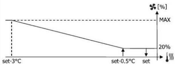
line
| Temperature | Value (%) | | :--- | :--- | | set-3°C | MAX | | set-0.5°C | 20% | | set | 20% |Raccordements hydrauliques
| Unité | Raccordement échangeur | |
| FW02ATN, FW03ATN,FW04ATN (2 tubes) | 1/2" gas F | |
| FW06ATN, FW07ATN,FW08ATN (2 tubes) | 3/4" gas F | |
| Rafraîchissement Chauffage | ||
| FW02AFN, FW04AFN (4 tubes) | 1/2" gas F | 1/2" gas F |
| FW06AFN, FW08AFN (4 tubes) | 3/4" gas F | 1/2" gas F |
natural_image
Technical line drawing of a mechanical assembly with no visible text or symbols»Fig.3
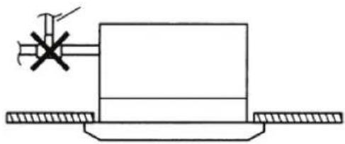
natural_image
Pure mechanical diagram showing a lever and base plate without any text, numbers, or symbolsMONTAGE UNITÉS À L'AIDE DES SCHÉMAS DIMENSIONNELS
natural_image
Technical line drawing of a hexagonal mechanical housing with mounting flanges and internal compartments (no text or symbols)»Fig.6
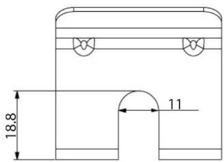
» Fig.9 FWI-A02-03-04
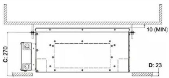
» Fig.10 FWI-A06-07-08
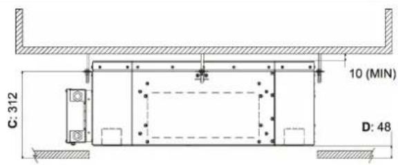
Montage panneau frontal/grille FPAN
Montage panneau frontal/grille FCND02A
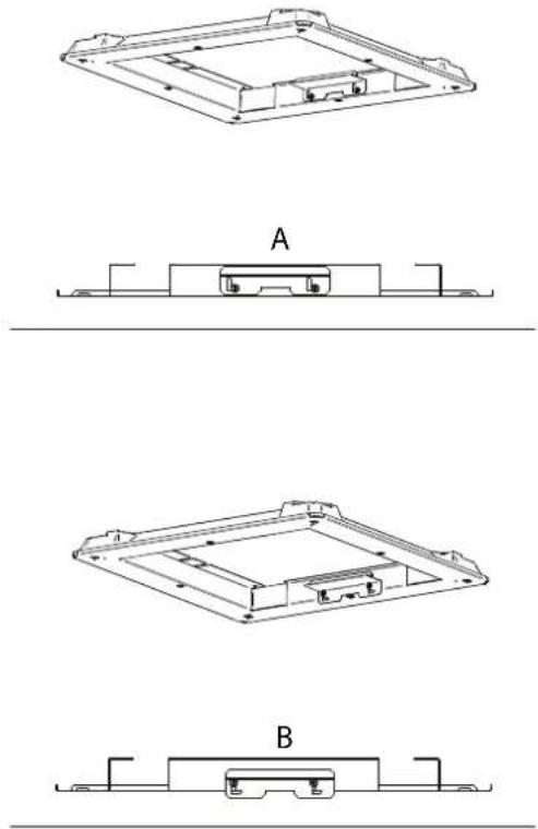
natural_image
Technical line drawings of a device casing with three views (A, B, and C) showing internal components and mounting brackets (no text or symbols)6 VÉRIFICATION FONCTIONNELLE
6.1 CONTRÔLES PRÉALABLES
S'assurer :
| Unité | Type vanne | Raccord | Δp min [kPa] | ||
| FW102ATN, FW103ATN, FW104ATN (2 tubes) | 2 voies | 3/4" M | 32 | ||
| FW106ATN, FW107ATN, FW108ATN (2 tubes) | 2 voies | 1 1/4" M | 20 | ||
| Rafraîchissement | Chauffage | ||||
| Unité | Type vanne | Raccord | Δp min [kPa] | Raccord | Δp min [kPa] |
| FW102AFN, FW104AFN (4 tubes) | 2 voies | 3/4" M | 16 | 3/4" M | 16 |
| FW106AFN, FW108AFN (4 tubes) | 2 voies | 1 1/4" M | 20 | 1" M | 16 |
8.5 RACCORDEMENT DE REFOULEMENT D'AIR DANS DES PIÈCES ATTENANTES
natural_image
Technical line drawing of a rectangular electronic device with mounting holes and a central panel (no text or symbols)||
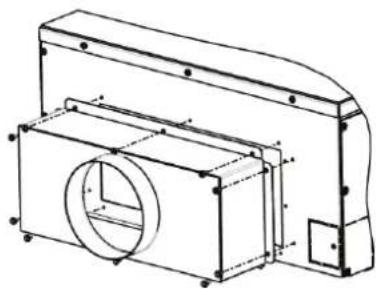
natural_image
Technical line drawing of a mechanical housing or enclosure with internal components and mounting holes (no text or symbols)III
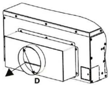
natural_image
Technical line drawing of a mechanical component with a circular feature and labeled point D (no text or symbols beyond label)9ENTRETIEN
9.2 NETTOYAGE GRILLE D'ASPIRATION FPAN
9.3 NETTOYAGE DU FILTRE À AIR GRILLE FCND02A
9.4 NETTOYAGE DU LE PANNEU DU FILTRE À AIR GRILLE FCND02A
— BN: Marron = phase alimentation pompe
— BU: Bleu = neutre alimentation pompe
— VH ON/OFF: Vanne ON/OFF eau chaud (4 tuyaux) (accessory)
— BN: Marron = phase alimentation vannes
— BU: Bleu = neutre alimentation vannes
Stromanschlüsse. S. 70
natural_image
Close-up of a white ventilation grille with uniform horizontal slats (no text or symbols visible)natural_image
Close-up of a white and black ceiling-mounted air conditioner unit with a textured grille (no text or symbols visible)ZUBEHÖR
natural_image
Technical line drawing of a curved mechanical component with internal channels and mounting brackets (no text or symbols)1 Fühlerhalterung
line
| Temperature | Percentage [%] | | ----------- | -------------- | | set-3°C | 20% | | set-0.5°C | 20% | | set | 20% |Hydraulikanschlüsse
| Einheit | Verbindung Wärmetauscher | |
| FW102ATN, FW103ATN, FW104ATN (2 Rohre) | 1/7" gas F | |
| FW105ATN, FW107ATN, FW108ATN (2 Rohre) | 3/4" gas F | |
| Kühlen | Heizen | |
| FW102ATN, FW104ATN (4 Rohre) | 1/2" gas F | 1/2" gas F |
| FW105ATN, FW108ATN (4 Rohre) | 3/4" gas F | 1/2" gas F |
natural_image
Line drawing of two metal tools with handles and a ring (no text or symbols)natural_image
Technical line drawing of a mechanical assembly with no visible text or symbols» Abb.3
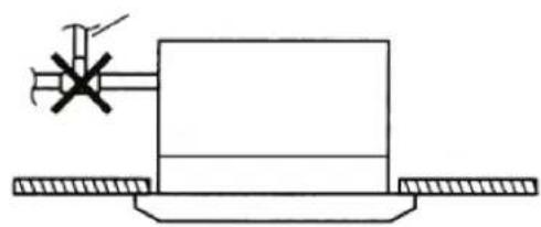
natural_image
Pure mechanical diagram showing a rectangular block with a cross mark and pipe, mounted on a base with flanges (no text or symbols)» Abb. 7
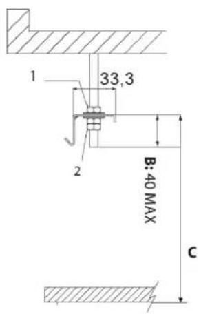
» Abb. 8
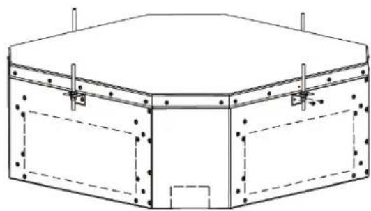
natural_image
Technical line drawing of a hexagonal mechanical housing with mounting holes and internal compartments (no text or symbols)Montage des Frontpaneels/des FPAN Gitters
Anbringen des Frontpaneels: (Abb.12)
Montage de Frontpaneel/de FCND02A Gitter
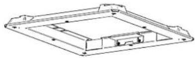
natural_image
Technical line drawing of a rectangular electronic component or housing (no text or symbols)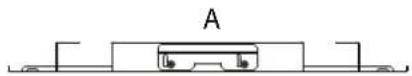

natural_image
Technical line drawing of a rectangular electronic component or enclosure with mounting holes and internal structure (no text or symbols)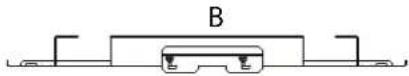
6.1 VORABKONTROLLEN
Sich vergewissern:
| Einheit Ventiltyp | Anschluss | KVS | ||
| FW102ATN, FW103ATN, FW104ATN (2 Rohe) | 2 Wege | 3/4" M | 2,8 | |
| FW106ATN, FW107ATN, FW108ATN (2 Rohe) | 2 Wege | 3/4" M | 4 | |
Kühlen
| Einheit | Ventiltyp | Anschluss | KVS | Anschluss | KVS |
| PWI02AFN, FWI04AFN (4 Rohre) | 2 Wegc | 3/4" M | 2,8 | 3/4" M | 2,8 |
| PWI06AFN, FWI08AFN (4 Rohre) | 2 Wegc | 3/4" M | 4 | 3/4" M | 2,8 |
8.2 ANGETRIEBENER 2-WEGE-VENTILSATZ PRESSURE INDEPENDENT
natural_image
Technical line drawing of a mechanical component with mounting holes and a curved body (no text or symbols)1 Kondenswasserablass
» Abb.16
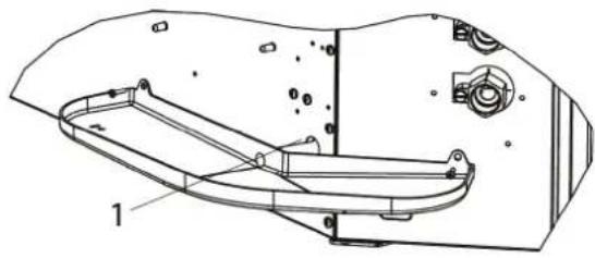
natural_image
Technical line drawing of a vehicle chassis frame with labeled components (no text or symbols present)1 Kondenswasserablass
natural_image
Simple line drawing of a rectangular device with two wheels and a central box (no text or symbols)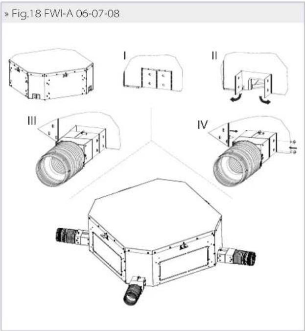
natural_image
Technical line drawing of a mechanical housing or enclosure with mounting holes and internal components (no text or symbols)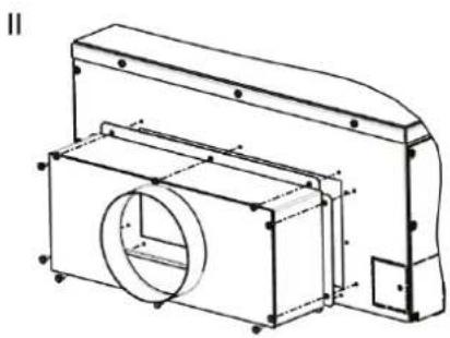
natural_image
Technical line drawing of a mechanical housing or enclosure with internal components and mounting brackets (no text or symbols)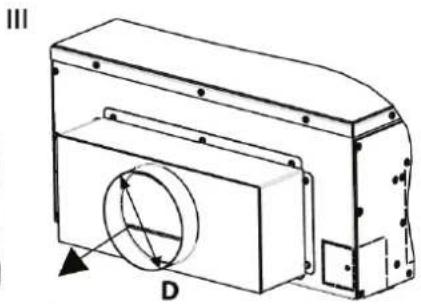
natural_image
Technical line drawing of a mechanical housing or enclosure with a circular component and labeled section D (no text or symbols beyond label)9WARTUNG
9.2 REINIGUNG DES ANSAUGGITTERS
9.3 REINIGUNG DES LUFTFILTERS FCND02A GITTER
» Abb.25
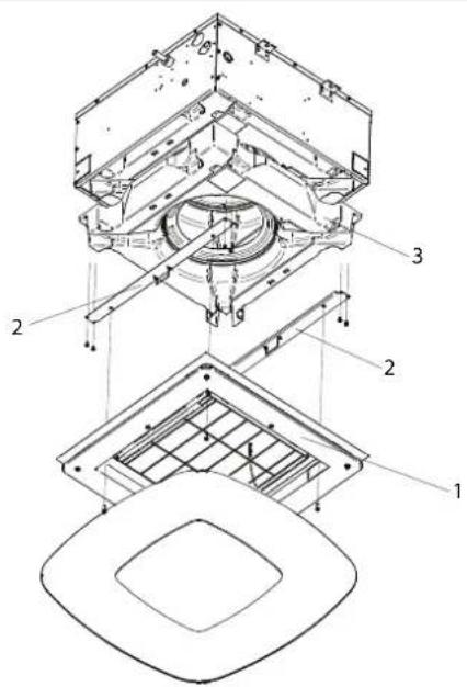
9.7 ANORMALER WASSERSTAND
natural_image
Close-up of a metallic ventilation grille with uniform horizontal slats (no text or symbols visible)Rejilla FCND02A: rejilla de design con efecto Coandă
natural_image
Close-up of a white and black ceiling-mounted air conditioner unit with a mesh grille (no text or symbols visible)ACCESORIOS
natural_image
Technical line drawing of a mechanical component with layered structure (no text or symbols)line
| Temperature | Value | | ----------- | ----- | | set-3°C | MAX | | set-0.5°C | 20% | | set | 20% |natural_image
Line drawing of two metal clips with handles and a looped end (no text or symbols)natural_image
Technical line drawing of a mechanical assembly with no visible text or symbols»Fig.3
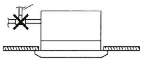
natural_image
Simple line drawing of a mechanical assembly with a central block and two side supports (no text or symbols)MONTAJE DE LA UNIDAD
natural_image
Technical line drawing of a hexagonal mechanical housing with mounting flanges and internal compartments (no text or symbols)»Fig.6
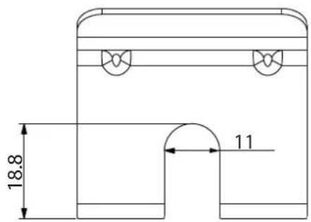
» Fig.9 FWI-A02-03-04
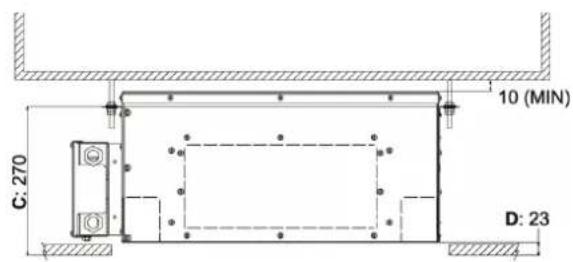
»Fig.7
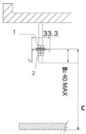
» Fig.10 FWI-A06-07-08
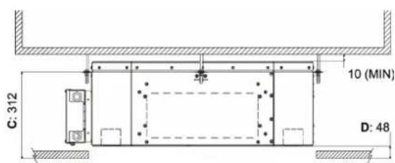
- Tuerca + arandela
- Arandela + tuerca + contratuerca
Para instalar el frente: (Fig.12)
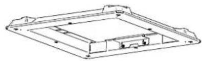
natural_image
Technical line drawing of a rectangular electronic component or enclosure with internal compartments and mounting holes (no text or symbols)
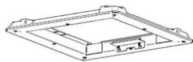
natural_image
Technical line drawing of a mechanical component with no visible text or symbols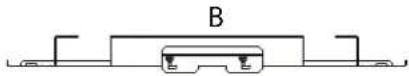
natural_image
Technical line drawing of a mechanical component with no visible text or symbolsnatural_image
Technical line drawing of a vehicle chassis frame with labeled components (no text or symbols present)» Fig. 17 FWI-A 02-03-04
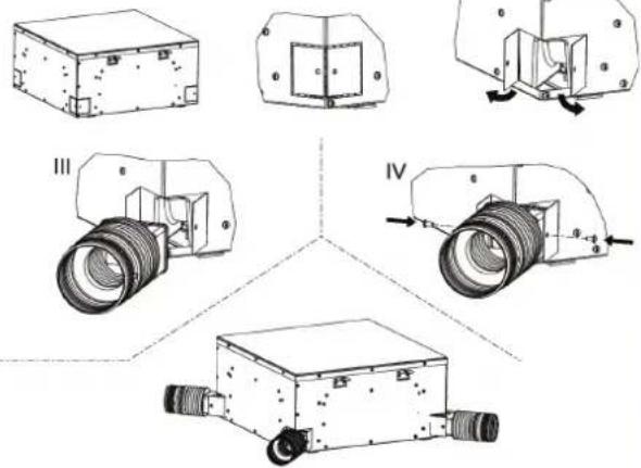
natural_image
Technical line drawing of a rectangular electronic device with mounting holes and a central panel (no text or symbols)||
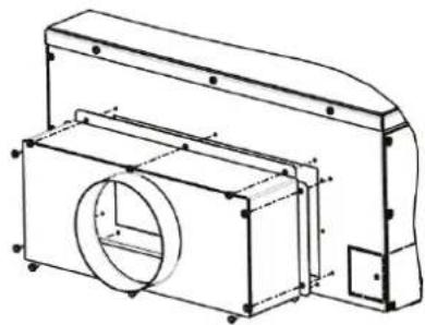
natural_image
Technical line drawing of a mechanical component with circular cutout and mounting bracket (no text or symbols)III
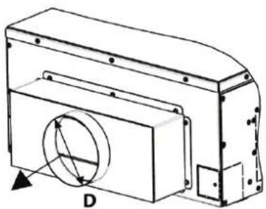
natural_image
Technical line drawing of a mechanical housing or enclosure with a circular component and mounting base (no text or symbols)9 MANTENIMIENTO
9.3 LIMPIEZA DEL FILTRO DE AIRE REJILLA FCND02A
9.4 LIMPIEZA DEL PANEL DE CIERRE DE LA REJILLA FCND02A
»Fig.25
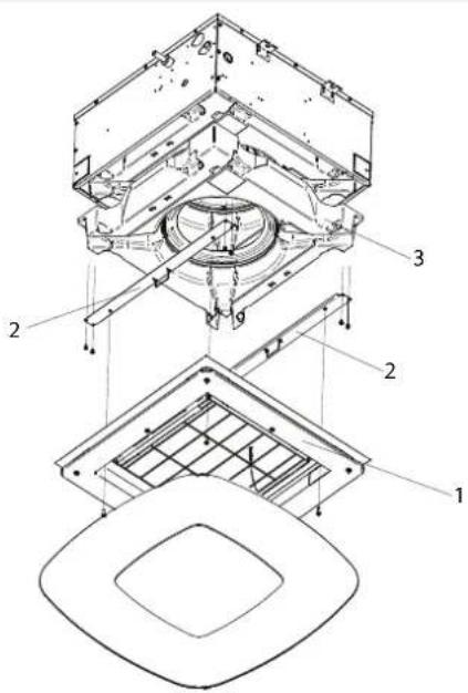
9.7 NIVEL ANÓMALO DE AGUA
POUŽÍVEJTE VHODNÉ OSOBNÍ OCHRANNÉ POMŮCKY (RUKAVICE, OCHRANNÉ BRÝLE)
natural_image
Close-up of a white ventilation grille with uniform slats (no text or symbols visible)natural_image
Close-up of a white and black ceiling-mounted air conditioner unit with a mesh grille (no text or symbols visible)PŘÍSLUŠENSTVÍ
1 Spona pro sondu
line
| Condition | Value [%] | |---|---| | set | 20 | | set+0.5℃ | 20 | | set+3℃ | MAX |» Ohřev
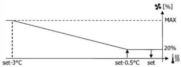
line
| Temperature | Value (%) | | :--- | :--- | | set-3°C | MAX | | set-0.5°C | 20 | | set | 20 |natural_image
Technical line drawing of a mechanical assembly with no visible text or symbols»Obr.3
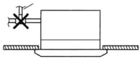
natural_image
Pure mechanical diagram showing a lever and base with no text or symbolsMONTÁŽ ROZMĚROVÝCH JEDNOTEK
natural_image
Technical line drawing of a hexagonal mechanical housing with mounting flanges and internal compartments (no text or symbols)»Obr.6
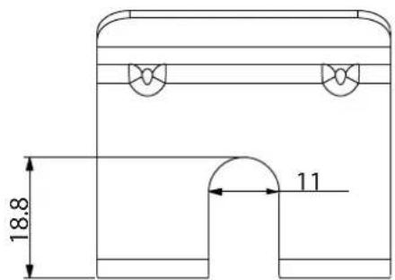
» Obr. 9 FWI-A02-03-04
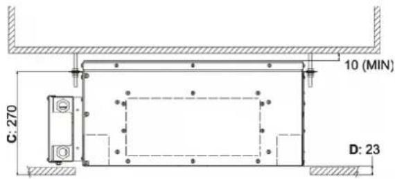
»Obr.10 FWI-A06-07-08
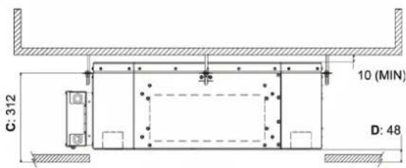
natural_image
Technical line drawing of a mechanical component with cross-sectional view A (no text or symbols)»Obr.13
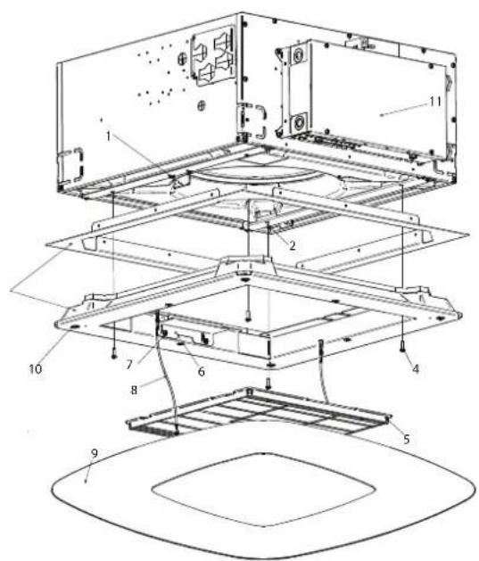
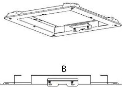
natural_image
Technical line drawing of a mechanical component with a top view and base view labeled B (no text or symbols present)6 FUNKČNÍ KONTROLA
6.1 PŘEDBĚŽNÉ KONTROLY
Ujistěte se:
natural_image
Technical line drawing of a mechanical component with no visible text or symbols1 Odvod kondenzátu
»Obr.16
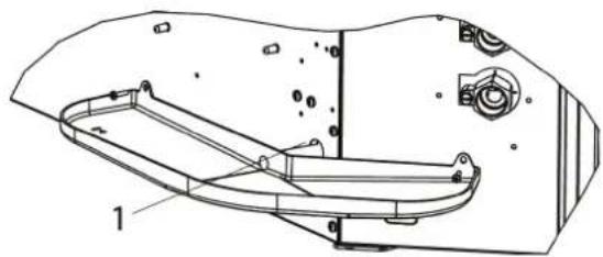
natural_image
Technical line drawing of a mechanical component with labeled parts (no text or symbols present)1 Odvod kondenzátu
natural_image
Simple line drawing of a rectangular box with three side connectors and a central wheel (no text or symbols)»Obr, 18 FWI-A 06-07-08
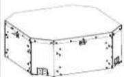
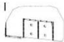
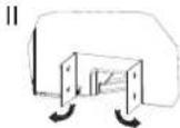
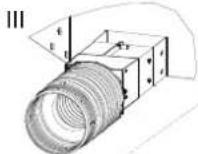
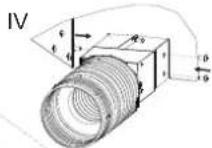
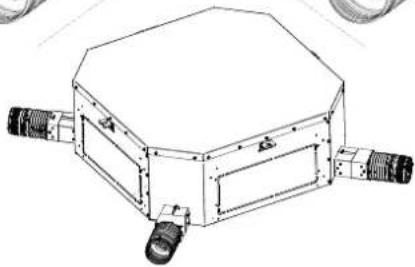
natural_image
Technical line drawing of a hexagonal mechanical device with four protruding ports (no text or symbols)8.5 PŘIPOJENÍ PŘÍVODU VZDUCHU V SOUSEDNÍCH MÍSTNOSTECH
natural_image
Technical line drawing of a mechanical housing or enclosure with mounting holes and internal components (no text or symbols)||

natural_image
Technical line drawing of a mechanical housing or enclosure with mounting brackets and internal components (no text or symbols)III
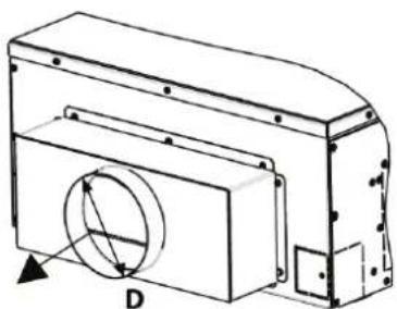
natural_image
Technical line drawing of a mechanical housing or enclosure with a circular component and mounting holes (no text or symbols)9ÚDRŽBA
9.3 Č IŠTĚNÍ MŘÍŽKY VZDUCHOVÉHO FILTRU FCND02A
9.4 ČIŠTĚNÍ UZAVÍRACÍHO PANELU MŘÍŽKY FCND02A
» Obr. 25
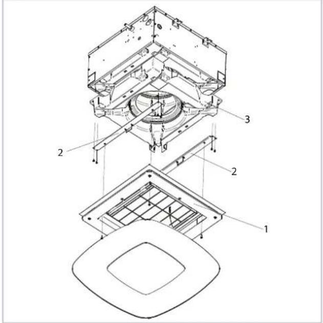
9.7 ABNORMÁLNÍ HLADINA VODY
natural_image
Close-up of a white ventilation grille with uniform horizontal slats (no text or symbols visible)Rešetka: dizajnerska rešetka s Coandă efektom FCND02A
natural_image
Close-up of a white and black ceiling-mounted air conditioner unit with a mesh grille (no text or symbols visible)OPREMA
| Elektroničke mikroprocesorske upravljačke ploče sa zaslonom | |||||
 | FWTOUCH 2,8" zaslon osjetljiv na dodir korismičkog sučelja za FWECSA kontrolu | FWE10 | Elektronički upravljač za kontrolu EC pretvarača ventilatora i jednog ili dva 230 V ON/OFF ventila | ||
 | FWECSAP Naponska ploča za upravljač FWECSA | E2C2PIC/PRP E4C2PIC/PRP | Dvosmjerni ventili, NEOVISNI O TLAKU, za modele s 1 ili 2 zavojnice | ||
| FWECSAC Korismičko sučelje sa zaslonom za upravljač FWECSA | E2C2 | Dvosmjerni ventili, ON/OFF ili MODULIRAJUĆI aktuatori, napajanje 230 V ili 24 V, hidraulični kompleti, za modele sa 1 ili 2 zavojnice | |||
| [GHHB] | FWECSA Mikroprocesorski upravljač sa zaslonom 3A | E2C3 | Trosmjerni ventili, ON/OFF ili MODULIRAJUĆI aktuatori, napajanje 230 V ili 24 V, hidraulični kompleti, za modele sa 1 ili 2 zavojnice | ||
 | FWHSKA Sonda za vlagu za upravljače FWECSA, FWECSA | Plenum, usisni moduli, usisne armature, dovod zraka i pokrovni namještaj | |||
 | FWTSKA Sonda za vodu za upravljače FWECSA , FWECSA | SPFA11A/ SPFA12A | Cjevčica za miješani dovod svježeg zraka | ||
| Elektroničke mikroprocesorske upravljačke ploče | PPAI02A/06 | Plenum za isporuku zraka | |||
4 PODATCI O DIMENZIJAMA
Na slici na stranici s. 163 - s. 161 navedeni su podatci o dimenzijama FWI-A i položaji hidrauličkih priključaka.
5 UGRADNJA
natural_image
Technical line drawing of a mechanical component with curved surfaces and dimension lines (no text or symbols)1 Držač sonde
Namjenska naredba (FWEC10 - FWECSA - FWEC3A)
Naredbe implementiraju logiku koja vam omogućuje postavljanje fiksne brzine prikazane na slici s analognim signalom od 3, 6, 8 V ili automatskom modulacijom brzine, čime se u potpunosti iskorištavaju prednosti EC motora.
line
| Temperature | Percentage [%] | | ----------- | -------------- | | set-3°C | 20% | | set-0.5°C | 20% | | set | 20% |Hidraulični priključci
| Jedinica | Priključak izmjenjivača | |
| FWI02ATN, FWI03ATN, FWI04ATN (2 cijevi) | 1/2" gas F | |
| FWI06ATN, FWI07ATN, FWI08ATN (2 cijevi) | 3/4" gas F | |
| Hlađenje | Grijanje | |
| FWI02AFN, FWI04AFN (4 cijevi) | 1/2" gas F | 1/2" gas F |
| FWI06AFN, FWI08AFN (4 cijevi) | 3/4" gas F | 1/2" gas F |
natural_image
Line drawing of two metal tools with handles and a ring (no text or symbols)— Pažljivo izolirajte dovodne i odvodne cijevi vode kao i uređaje ugrađene na mreži (zaporni ventili, ...). Koristite materijal koji odgovara uvjetima uporabe i temperaturi vode.
natural_image
Technical line drawing of a mechanical assembly with no visible text or symbols»Fig.3
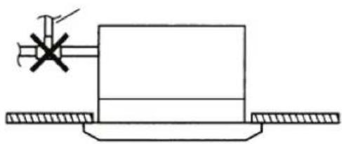
natural_image
Pure mechanical diagram showing a lever and base plate without any text, numbers, or symbolsMONTAŽA DIMENZIJSKIH JEDINICA
natural_image
Technical line drawing of a hexagonal mechanical housing with mounting holes and internal compartments (no text or symbols)» Fig.9 FWI-A02-03-04
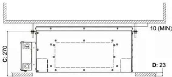
» Fig.10 FWI-A06-07-08
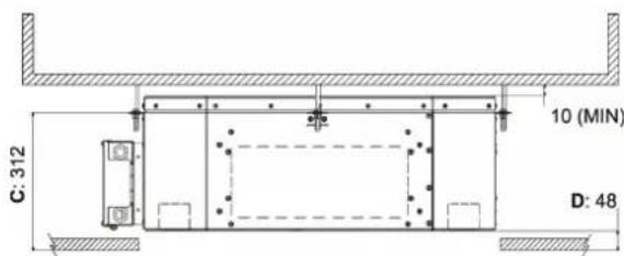
Za postavljanje prednje strane: (Fig. 12)
— Okrenite dvije kopče za zaključavanje (5) prema dolje.
— Zakačite okvir ploče (6) za jedinicu pomoću dvije kuke (7) tako da ih spojite sa stezaljkama za zaključavanje (5).
— Provjerite točan položaj okvira panela u odnosu na spušteni strop. Ako je potrebno, prilagodite položaj unutarnje jedinice.
— Pričvrstite okvir ploče na jedinicu koristeći posebne isporučene vijke i podloške (8).
— Postavite rešetku (3) na mjesto, provjerite je li filtar (9) ispravno postavljen.
Montaža prednje strane/rešetke FCND02A
Prednja strana/rešetka, dostupna u verzijama FWI 02-03-04, isporučuje se u zasebnom paketu:
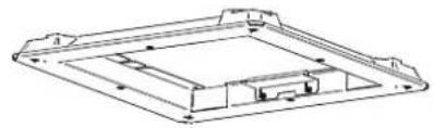
natural_image
Technical line drawing of a rectangular electronic component with mounting holes and internal channels (no text or symbols)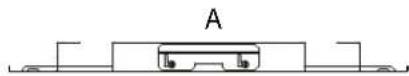

natural_image
Technical line drawing of a mechanical component with mounting holes and internal channels (no text or symbols)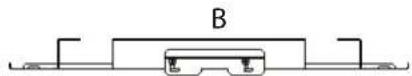
natural_image
Technical line drawing of a mechanical component with no visible text or symbols1 Odvod kondenzata
»Fig.16
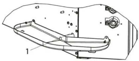
natural_image
Technical line drawing of a mechanical component with labeled parts (no text or symbols present)1 Odvod kondenzata

PAŽNJA: Ugradnja pomoćne posude je obavezna.
8.4 PRIKLJUČAK ZA USIS PRIMARNOG ZRAKA KOJI TREBA TRETIRATI
» Fig.18 FWI-A 06-07-08
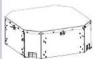
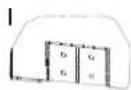
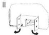
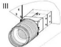
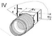

natural_image
Technical line drawing of a hexagonal mechanical or electronic device with four ports (no text or symbols)8.5 PRIKLJUČAK ZA DOVOD ZRAKA U SUSJEDNE PROSTORIJE
natural_image
Technical line drawing of a mechanical housing or enclosure with mounting holes and a central panel (no text or symbols)||
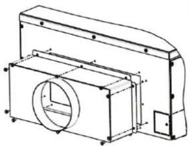
natural_image
Technical line drawing of a mechanical housing or enclosure with internal components and mounting holes (no text or symbols)III
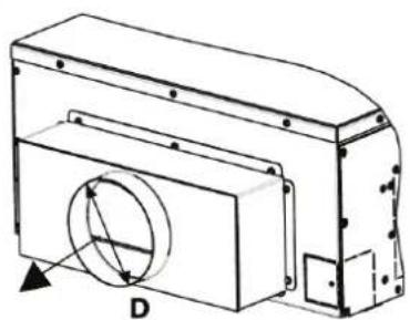
natural_image
Technical line drawing of a mechanical housing or enclosure with a circular component and mounting holes (no text or symbols)9ODRŽAVANJE
9.2 ČIŠĆENJE FPAN USISNE REŠETKE
9.3 ČIŠĆENJE FILTRA ZRAKA REŠETKE FCND02A
9.4 ČIŠĆENJE PLOČE ZA ZATVARANJE REŠETKE FCND02A
— Koristite meku, suhu krpu.
— Nikada nemojte sipati tekućinu na uređaj jer to može uzrokovati strujni udar i oštetiti unutarnje dijelove.
— Nikada ne koristite agresivna kemijska otapala.
⚠ UPOZORENJE: APSOLUTNO JE ZABRANJENO KORISTITI ABRA-ZIVNE ALATE bilo koje vrste. Inače riskirate nepovratno ugroziti površinu grafi ke.
9.5ELEKTRIČNIORMAR
Jednom godišnje provjerite ispravnost brtvljenja električnih žica na njihovim priključnim stezaljkama.
9.6 DODATNO ODRŽAVANJE
Pregled, čišćenje ili zamjena unutarnjih komponenti zahtijevaju rastavljanje glavnog spremnika kondenzata.
Uklanjanje spremnika (Fig. 24 i Fig. 25):
— Uklonite usisnu rešetku (za FPAN rešetku); Uklonite DIBOND ploču za zatvaranje povlačenjem prema dolje, odvajajući je od jedinice (za rešetku FCND02A).
— Ispraznite kondenziranu vodu preostalu u spremniku u kantu pomoću crpke kroz otvor za odvod kondenzata u pomoćnoj posudi (Fig. 15 i Fig. 16).
— Uklonite prednji sklop (tijelo ploče) (1) tako da odvrnete četiri pričvrsna vijka. Uklonite potporne ploče spremnika (2) (3) uklanjanjem vijaka.
— Uklonite spremnik pažljivo rukujući njime.
— Očistite unutrašnjost spremnika.
— Provjerite je li izmjenjivač topline čist. Po potrebi obrišite prašinu usisavačem s gumenom mlaznicom, pazeći da ne oštetite peraje.
Ponovno sastavljanje spremnika:
— Vratite spremnik (3) na mjesto s odgovarajućim potpornim pločama (2) i zategnite pričvrsne vijke.
»Fig.25
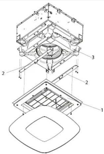
9.7 NEDOZVOLJENA RAZINA VODE
U slučaju nenormalnog porasta vode u spremniku kondenzata (zbog neispravne crpke, prljavog spremnika, začepljene odvodne cijevi,...), sigurnosni kontakt (plovak) zatvara regulacijske ventile.
10 RJEŠAVANJE KVAROVA
— BN (L2): Smedi = filtar IN faze
— BU (N4): Plavi = neutralni IN filtar
— BK (U1): Crni = filtar OUT faze
— BU (U3): Plavi = neutralni OUT filtar
— MV: Motor ventilatora
— PRETVARAČ: Pretvarač motora ventilatora
— BN: Smedi = faza napajanja motora
— BU: Plavi = neutralno napajanje motora
— red: Crveni = 0-10 Vdc upravljački signal
— black: Crni = GND upravljački signal
— MP: Crpka za odvod kondenzata
— FLOAT SWITCH: Plovak
— BN: Smeđi = faza napajanja crpke
— BU: Plavi = neutralno napajanje crpke
— BK: Crni = signal alarma plovka
— GY: Sivi = zajednički alarm plovka
— VC ON/OFF: Ventil ON/OFF hladne/tople vode (sustav s 2 cijevi) (dodatna oprema); Ventil ON/OFF hladne vode (susta s 4 cijevi) (dodatna oprema)
— VH ON/OFF: Ventil ON/OFF tople vode (sustav s 4 cijevi) (dodatna oprema)
| Model Distanța [mm]. | |
| FWI-A 02-03-04 310 | |
| FWI-A 06-07-08 360 |
natural_image
Close-up of a white ventilation grille with uniform slats (no text or symbols visible)natural_image
Close-up of a white and black ceiling-mounted air conditioner unit with a mesh grille (no text or symbols visible)ACCESORII
line
| Condition | Value [%] | |---|---| | set | 20 | | set+0.5°C | 20 | | set+3°C | MAX |»Încălzire

line
| Temperature | Value (%) | | :--- | :--- | | set-3°C | MAX | | set-0.5°C | 20 | | set | 20 |Conexiuni hidraulice
| Unități | Conexiune schimbător | |
| FWI02ATN, FWI03ATN, FWI04ATN (2 jevi) | 1/2" gaz F | |
| FWI06ATN, FWI07ATN, FWI08ATN (2 jevi) | 3/4" gaz F | |
| Răcire | Încălzire | |
| FWI02AFN, FWI04AFN (4 jevi) | 1/2" gaz F | 1/2" gaz F |
| FWI06AFN, FWI08AFN (4 jevi) | 3/4" gaz F | 1/2" gaz F |
natural_image
Technical line drawing of a mechanical assembly with no visible text or symbols»Fig.3
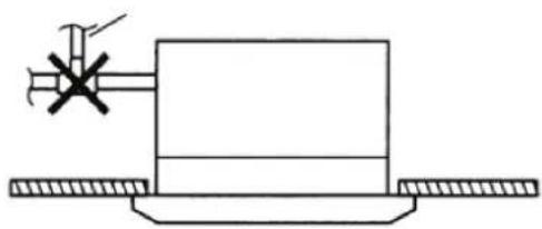
natural_image
Pure technical diagram of a mechanical assembly with no text, numbers, or symbolsMONTAREA UNITĂȚILOR DIMENSIONALE
natural_image
Technical line drawing of a hexagonal mechanical housing with mounting flanges and internal compartments (no text or symbols)» Fig.6
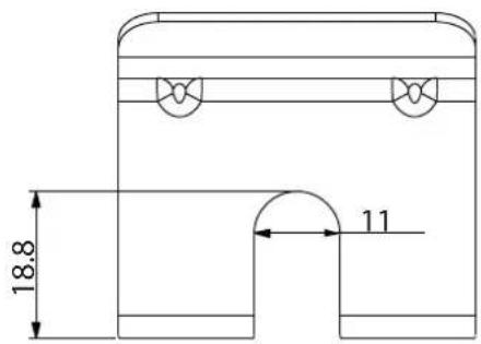
» Fig.9 FWI-A02-03-04
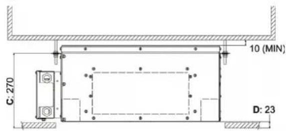
» Fig.10 FWI-A06-07-08
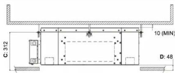
Pentru a instala panoul frontal: (Fig. 12)
natural_image
Technical line drawing of a rectangular electronic component with internal channels and mounting base, labeled A (no text or symbols present)»Fig.13
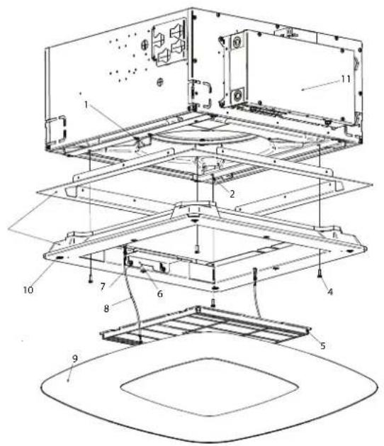
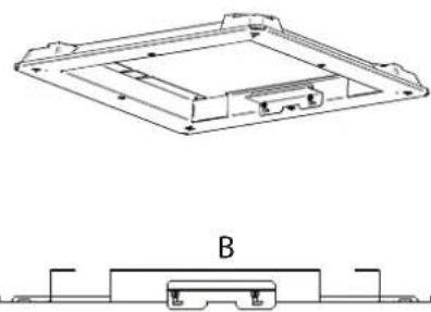
natural_image
Technical line drawing of a rectangular electronic component with mounting holes and internal structure, labeled B (no text or symbols present)6 VERIFICARE FUNCTIONALĂ
6.1 CONTROALE PRELIMINARE
Asigurati-vă că:
» Fig.18 FWI-A 06-07-08
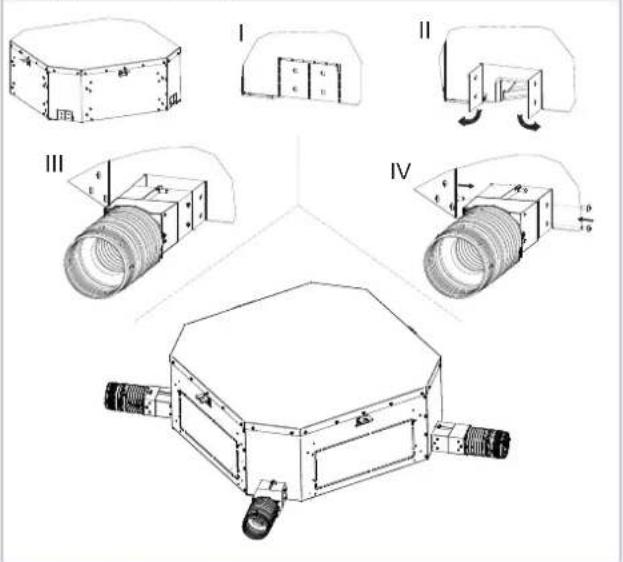
8.5 RACORDUL DE ALIMENTARE CU AER ÎN ÎNCĂPERI ADIACENTE
natural_image
Technical line drawing of a rectangular electronic component with mounting holes and internal compartments (no text or symbols)||
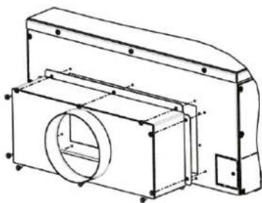
natural_image
Technical line drawing of a mechanical housing or enclosure with internal components and mounting holes (no text or symbols)III
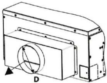
natural_image
Technical line drawing of a mechanical component with a circular cutout and labeled point D (no text or symbols beyond label)9 ÎNTRETINERE
9.2 CURĂȚAREA GRILEI DE ADMISIE FPAN
9.3 CURĂȚAREA FILTRULUI DE AER AL GRILEI FCND02A
9.4 CURĂTAREA CAPACULUI GRILEI FCND02A
»Fig.25

9.7 NIVEL ANORMAL AL APEI
1)
Clip di bloccaggio / Locking clips / Clips de blocage / Einspanndips / Clip de bloqueo / Zajišťovací Klp / Kvačica za zaključavanje / Cleme de blocare
2)
Tiranti / Tæ rods / Tirants / Spannvorrichtungen / Tirantes / Tåhla / Šipke / Bare de legāturā
3)
Vasca per la raacota del la condensa / Condensate drip tray / Bac de collecte des condensats / Kondenswassersammelbecken / Depósito para el líquido de condensación / Sběmá nádoba na kondenzát / Spremnik za skup-janje kondenzata / Revervor de colectare a condensului
4)
Pompa per lo scarico della condensa / Condensate drainage pump / Pompe d'évacuation des condensats / Kondenswasserablasspump / Bomba de descarça de condensado / Cercaplo pro odvod kondenzátu / Crpka za odvod kondenzata / Pompa de evacuare a condensului
5)
Scambiatore di calore / Heat exchanger / Changeur de chaleur / Kältemittel / Intercambiador de calor / Vyměnik tepla / Izmjenjivač topline / Schimbátor de cálduřa
6)
Ventilatore / Fan / Ventilateur / Lüfter / Ventilador / Ventilator / Ventilator / Ventilator
7)
Motore / Motor / Motour / Motor / Motor / Motor / Motor
8)
Coibentazione interna / Internal insulation / Isolation interne / Wärmedämmung innen / Aislamiento interno / Vnitřní izolace / Unutamja izolacija / Izolatje interioará
9)
Lamiera laterale / Lateral sheet metal / Tôle latérale / Seitenoplech / Chapa lateral / Bočni deska / Bočni lim / Tabla laterali
10)
Lamiera / Sheet / Tôle / Blech / Chapa / Plech / Lim / Tabla
11)
Staffe per il supporto dello scambiatore / Exchanger support brackets / Bride de soutien de l'Exchangeur / Haltebügel des Wärmetauschers / Estribos de apoyo del intercambiador / Držáky pro podpēru výměníku tepla / Nosači za držanje izmjenjivača / Suporturi pentru suportul schimbătorului de căldură
12)
Scatola elettrica / Electric box / Boîtier électrique / Verteilungskasten / Caja conexiones eléctricas / Elektrická skíň / Električna kutija / Cutia electrica
» Esploso unità FWI-A 06-07-08 / Unit exploded view FWI-A 06-07-08 / Éclaté unité FWI-A 06-07-08 / Explosionszeichnung Einheit FWI-A 06-07-08 / Despiece unidad FWI-A 06-07-08 / Nákres jednotky FWI-A 06-07-08 / Shematski prikaz jedinice FWI-A 06-07-08 / Vedere explozivă unitate FWI-A 06-07-08
» 13.2
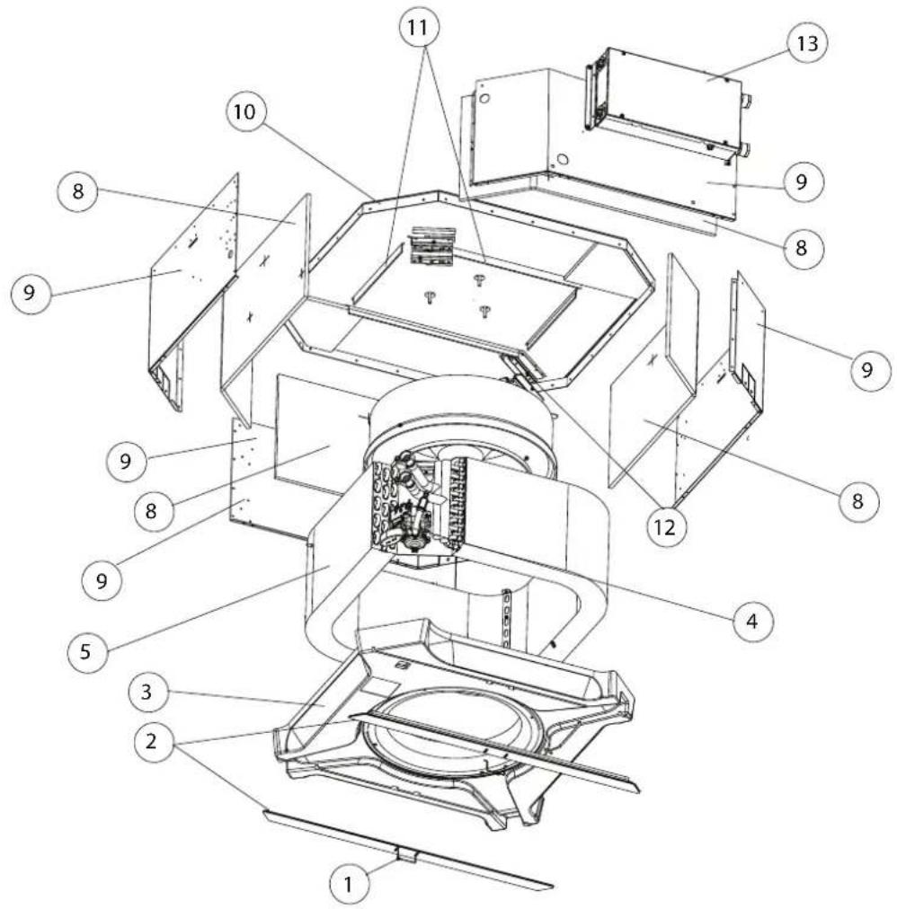
1)
Clip di bloccaggio / Locking clips / Clips de blocage / Linspannclips / Clip de bloqueo / Zajišťovaci Klip / Kvačica za zakijučavanje / Cleme de blocare
2)
Tiranti / Tie rods / Tirants / Spannvorrichtungen / Tirantes / Táhla / Šipke / Bare de legatură
3)
Vasca per la raccolta della condensa / Condensate drip tray / Bac de collecte des condensats / Kondenswassensammelbecken / Depósito para el líquido de condensación / Sběrná nádoba na kondenzár / Spremnik za skupljanje kondenzala / Rezervor de colectare a condensului
4)
Pompa per lo scarico della condensa / Condensate drainage pump / Pompe d'évacuation des condensats / Kondenswasserablasspumpe / Bomba de descarga de condensado / Cerpadlo pro odvod kondenzátu / Cróka za odvod kondenzata / Pompa de evacuare a condensului
5)
Scambiatore di calore / Heal exchanger / Échangeur de chaleur / Kälternitel / Intercambidor de calor / Výrnénik tepla / Izmjenjivač topline / Schimbátor de căldura
6)
Gruppo motoventilante / Fan drive assembly / Groupe moto-ventilateur / Lüftungsmotoreinheit / Grupo motoventilador / Jednotka motorovéno ventilátoru / Jedinica motora ventilatora / Unitate motor-ventilator
7)
Colbentazione interna / internal insulation / Isolation interne / Wärmedämmung innen / Aislamento interno / Vinithi izolace / Unutamja izolacija / Izolatie intericarä
8)
Lamiera laterale / Lateral sheet metal / Tole latérale / Seitenblech / Chapa lateral / Bočni deska / Bočni lim / Tabla lateralá
9)
Posteriore in lamiera / Sheet metal back / Panneau postérieur en tôle / Rückseite aus Blech / Posterior de chapa / Zadni plech / Strażnji lim / Partea din spate din tabla
10)
Staffe di rinforzo / Reinforcement brackets / Brides de renfort / Verstärkungsbügel / Estribos de refuerzo / Výztužné konzoly / Nosači za pojačanje / Suporturi de armare
11)
Staffe per il supporto del lo scambiatore / Exchanger support brackets / Bride de soutien de l'échangeur / Halhebügel des Wärmetauschers / Estribos de apoyo del intercambiador / Držáky pro podpēru výměniku tepla / Nosači za držanje izmjenjivača / Suporturi pentru suportul schimbătorului de cădură
12)
Scalo'a eletrica / Electric box / Boîtier électrique / Vertellungskasten / Caja conexiones eléctricas / Elektrická skífiń / Elektricna kutija / Cutia electrică
» Dimensionale FWI-A 02-03-04 2 tubi / Dimensional drawing FWI-A 02-03-04, 2 pipes / Schéma dimensionnel FWI-A 02-03-04 2 tuyaux / Abmessungszeichnung FWI-A 02-03-04 2 Rohre / Dibujo dimensional FWI-A 02-03-04 2 tubos / Rozměrový nákres FWI-A 02-03-04 2 trubky / Dimenzionalno FWI-A 02-03-04 s 2 cijevi / Schiţă dimensională FWI-A 02-03-04 2 tevi
» 13.3
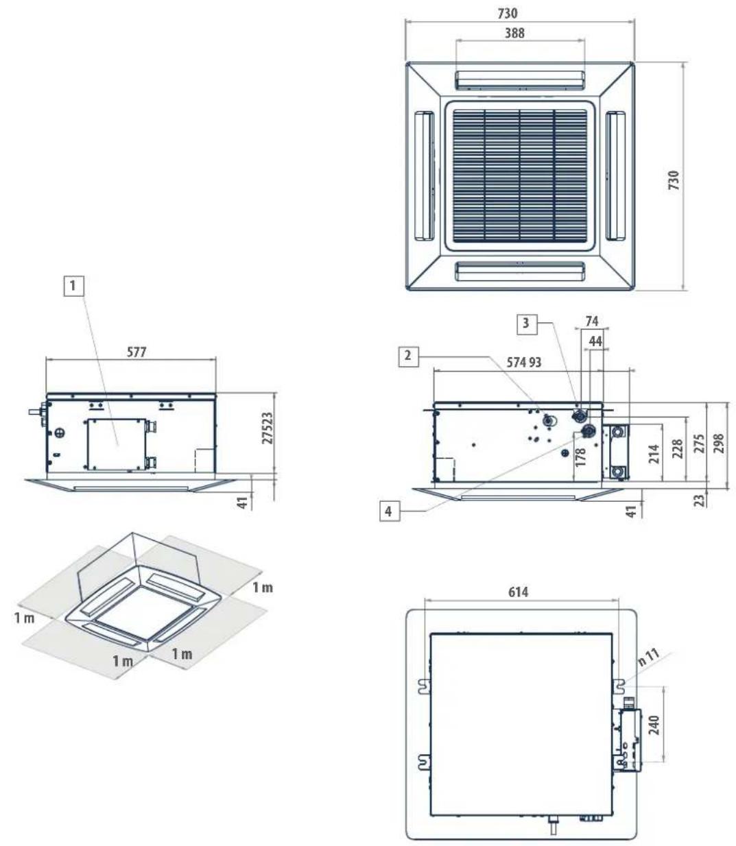
LEGENDA / LEGEND / LÉGENDE / LEGENDE / LEYENDA / VYSVĚTLIVKY / POJAŠNJENJE / LEGENDA
1)
Scatola elettrica / Electric box / Boitier électrique / Verteilungskasten / Caja conexiones eléctricas / Llektricka skrin / Llektricna kutja / Cutia electrica
2)
Scarico condensa e 10 / Condensate discharge e 10 / Purge des condensats e 10 / Kondenswasserablass e 10 / Descarga condensados e 10 / Odvod kondenzátu e 10 / Odvod kondenzata a 10 / Evacuarca condensului a 10
3)
Jscita acqua o 1/2" gas femmina / Water outlet o 1/2" ferma e gas / Sorile d'eau o 1/2" gaz femme / Wasserauslauf o 1/2" Innengewinde gas / Salida agua o 1/2" hembra gas / Výstup vody o 1/2" plynová zásuvka / Izlaz vode o 1/2" za plin, ženski / leşire de apà o 1/2" gaz mamá
4}
Entrata acqua o 1/2" gas lemmina /'Water inlet o 1/2" female gas / Entrée d'eau o 1/2" gaz lemme /'Wassereinlauf o 1/2" Innengewinde gas / Entrada agua o 1/2" hembra gas / Pffvod vody o 1/2" plymová zásueva / Ulaz vode o 1/2" za plin, ženski / intrare de apó o 1/2" gaz mamá
» Dimensionale FWI-A 06-07-08 2 tubi / Dimensional drawing FWI-A 06-07-08, 2 pipes / Schéma dimensionnel FWI-A 06-07-08 2 tuyaux / Abmessungszeichnung FWI-A 06-07-08 2 Rohre / Dibujo dimensional FWI-A 06-07-08 2 tubos / Rozměrový nákres FWI-A 06-07-08 2 trubky / Dimenzionalno FWI-A 06-07-08 s 2 cijevi / Schiţă dimensională FWI-A 06-07-08 2 tevi
» 13.4
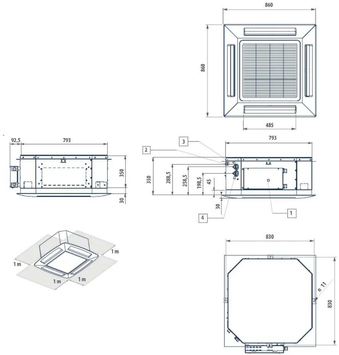
LEGENDA / LEGEND / LÉGENDE / LEGENDE / LEYENDA / VYSVĚTLIVKY / POJAŠNJENJE / LEGENDA
1) Scato la elettrica / Electric box / Böltier électrique / Verteilungskasten / Caja conexiones eléctricas / Elektrická sklih / Elektríčna kutija / Cutia electrică
2)
Scarico condensa a 10 / Condensate discharge a 10 / Purge des condensats a 10 / Kondenswasserablass a 10 / Descarqa condensados a 10 / Ocvod kondenzátu a 10 / Ocvod kondenzata a 10 / Evacuarea condensului a 10
3)
Uszta acqua o 3/4" gas femmina / Water outlet o 3/4" female gas / Sortie d'eau o 3/4" gaz femme / Wasserauslauf o 3/4" Innengewinde gas / Salida agua o 3/4" hembra gas / Vystup vody o 3/4" plynovi zásuvka / Iziaz vode o 3/4" za plin, žemski / Iesire de apá o 3/4" gaz mamá
4)
Entrata zópu a 3/4" gas femmina / Water inlet a 3/4" female gas / Entrée d'eau a 3/4" gaz femme / Wassereinauf a 3/4" Innengewinde gas / Entrada agua a 3/4" hembra gas / Vstup vody a 3/4" plynová zásuvka / Ullaz vode a 3/4" za plin, ženski / Intrare de apa a 3/4" gaz memá
» Dimensionale FWI-A 02-04 4 tubi / Dimensional drawing FWI-A 02-04, 4 pipes / Schéma dimensionnel FWI-A 02-04 4 tuyaux / Abmessungszeichnung FWI-A 02-04 4 Rohre / Dibujo dimensional FWI-A 02-04 4 tubos / Rozměrový nákres FWI-A 02-04 4 trubky / Dimenzionalno FWI-A 02-04 s 4 cijevi / Schiţă dimensională FWI-A 02-04 4 tevi
» 13.5
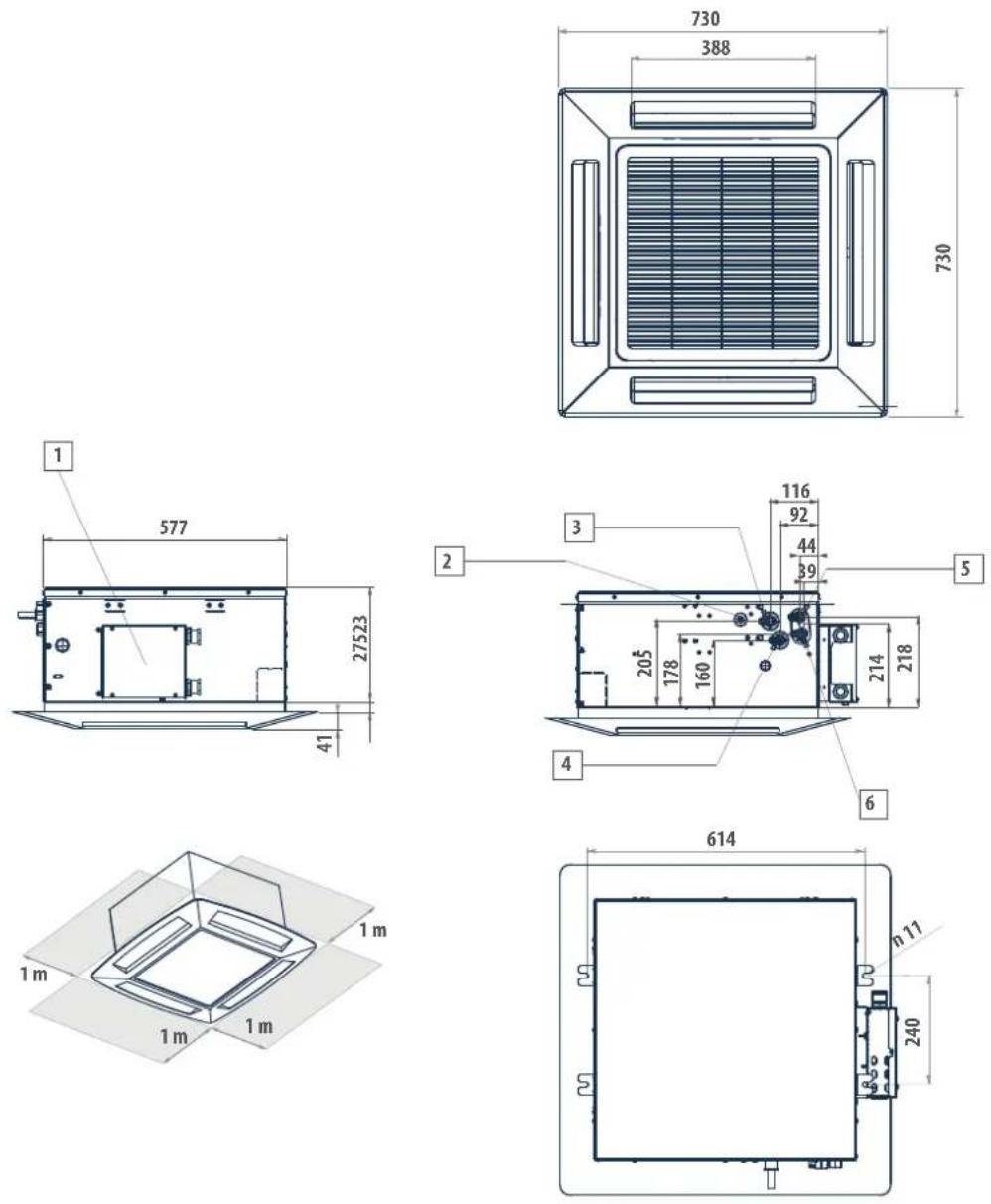
LEGENDA / LEGEND / LÉGENDE / LEGENDE / LEYENDA / VYSVĚTLIVKY / POJAŠNJENJE / LEGENDA
1)
Scatola elettrica / Electric box / Boitier electrique / Verteilungskasten / Caja conexiones eléctricas / Elektrická skřin / Električna kutja / Cuta electrică
2)
Scarico condensa e 10 / Condensate discharge e 10 / Purge des condensats e 10 / Kondenswasserablass e 10 / Descarga condensados e 10 / Odvod kondenzatu e 10 / Odvod kondenzata e 10 / Evacuarea condensului e 10
3)
Usicta acqua scambiotore raffredicamento 1/2" gas F / Cooling exchanger water outlet, 1/2" gas F / Sortie eau échangeur rafraichissement 1/2" gaz F / Wasserauslass kühlungswärmetauscher 1/2" BSP F / Salida agua intercambiador enfriamiento 1/2" gas F / Výstup vody z chladickho výméniku 1/2" plyn F / izlaz vode iz lizmenjivača hlaženja 1/2" plin F / legre apá schimatoor de caldurá rácie 1/2" gaz F
4)
Entrata acqua scambiatore rallreddamento 1/3" gas F / Cooling exchanger water inlet, 1/2" gas F / Entrée eau échangeur rafrachissement 1/2" gaz F / Wassereinlass Kühlungswärmelauscher 1/2" BSP F / Entrada agua intercambiador enñamiento 1/2" gas F / Přívod vody do chladicho vyměniku 1/2" plyn F / Ulaz voce iz izmjenjivača hlađenja 1/2" plin F / Intrare apá in schimbátor de rădire 1/2" gaz F
5)
Uskita acqua scambielore riscaldamento 1/2" gas F / Heating exchanger water outlet, 1/2" gas F / Sonie eau échangeur chauffage 1/2" gaz F / Wasserauslass Heizungswärmetauscher 1/2" BSP F / Salida agua intercambiador calentamiento 1/2" gas F / Výstup vody z topného výméníku 1/2" plyn F / Izlaz vode izmjenjvača topline 1/2" plin F / lejre apá schimibator de cálduřá încálzne 1/2" gaz F
6)
Entrata acqua scambiatore riscaldamento 1/2" gas F / Heating exchanger water inlet, 1/2" gas F / Entrée eau échangeur chauffage 1/2" gaz F / Wassereinlass Heizungswarmmetauscher 1/2" BSP F / Entrada agua intercambiador calentamiento 1/2" gas F / Přívod vody do topného výměníku 1/2" plyn F / Ulaž vode izmjenjivača topline 1/2" plin F / Intrare apá schimbátor de cădură 1/2" gaz F
» Dimensionale FWI-A 06-08 4 tubi / Dimensional drawing FWI-A 06-08, 4 pipes / Schéma dimensionnel FWI-A 06-08 4 tuyaux / Abmessungszeichnung FWI-A 06-08 4 Rohre / Dibujo dimensional FWI-A 06-08 4 tubos / Rozměrový nákres FWI-A 06-08 4 trubky / Dimenzionalno FWI-A 06-08 s 4 cijevi / Schiţă dimensională FWI-A 06-08 4 tevi
» 13.6
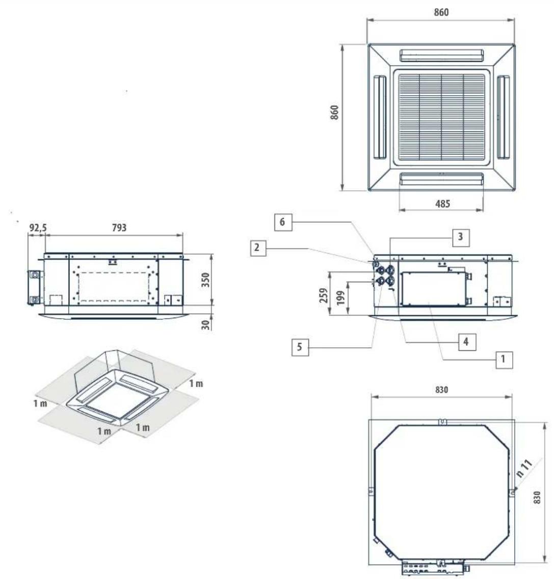
LEGENDA / LEGEND / LÉGENDE / LEGENDE / LEYENDA / VYSVĚTLIVKY / POJAŠNJENJE / LEGENDA
1)
Scatola elettrica / Electric box / Boitier électrique / Verteilungskasten / Caja conexiones eléctricas / Llektrická skriň / Llektrična kutija / Cutia electrica
2)
Scarico condensa a 10 / Condensale discharge a 10 / Purge des condensals a 10 / Kondenswasserablass a 10 / Descarga condensados a 10 / Odvod kondenzälu a 10 / Odvod kondenzata a 10 / Evacuarea condensului a 10
3)
Uskiz a quoca scambialore raffreddamento 3/4" gas F / Cooling exchanger water outlet, 3/4" gas F / Sortie eau échangeur rafratchissement 3/4" gaz F / Wasserauslass Kühlungswärmelauscher 3/4" BSP F / Salida agua intercambiador enfiramiento 3/4" gas F / Výstup vody z chladčilo výměníku 3/4" plyn F / blaz vode iz izmjenjivaša hlađenja 3/4" plin F / lesire aša schimbátor de caldurá tăirci 3/4" gaz F
4)
Entrata acqua scambiatore raffricicamento 3/4" gas F / Cooling exchanger water in e, 3/4" gas F / Entrée eau échangeur rafraichissement 3/4" gaz F / Wassereinlass Künungswärmetauscher 3/4" BSP F / Entrada agua intercambiador entia mento 3/4" gas F / Pflood vody do chladikno výměníku 3/4" plyn F / Ulaž vode iz izmjenjivača hlađenija 3/4" plin F / Intrare apä in schlimbátor de récie 3/4" gaz F
5)
Jscita acqua scambiatore riscaldamento 1/2" gas F / Healing exchanger water outlet, 1/7" gas F / Sortie eau échangeur chauffage 1/3" gaz F / Wasserauslass Heizungswärmetauscher 1/2" BSP F / Saïda agua intercambiador calentamiento 1/2" gas F / Výstup vody z topného vyměníku 1/2" plyn F / izlaz vode izmijonjivača topline 1/2" plin F / lejire aoá schimbátor de cálduřa încálzire 1/2" gaz F
6)
Entrata acqua scambiatore riscaldamento 1/2" gas F / Heating exchanger water inlet, 1/2" gas F / Entrée eau échangeur chanillage 1/2" gaz F / Wassereinlass Heizungswärmelauscher 1/2" BSP F / Entrada agua intercambiador calentamiento 1/2" gas F / Přívod vody do topného výměníku 1/2" plyn F / Ulaž vode izmjenljivača topline 1/2" plin F / intrare apá schimbátor de caldurá 1/2" gaz F
FWI-A 02 03 04 06 07 08
Peso / Hmotnost / Težina / Greutate kg 23 + 2,5 24 + 2,5 24 + 2,5 42 + 5 43 + 5 43 + 5
» Dimensionale FWI-A 02-03-04 + FCND02A / Dimensional drawing FWI-A 02-03-04 + FCND02 / Schéma dimensionnel FWI-A 02-03-04 + FCND02 / Abmessungszeichnung FWI-A 02-03-04 + FCND02 / Dibujo dimensional FWI-A 02-03-04 + FCND02 / Rozměrový nákres FWI-A 02-03-04 + FCND02A / Dimenzionalno FWI-A 02-03-04 + FCND02A / Schiţă dimensionalä FWI-A 02-03-04 + FCND02A
» 13.7
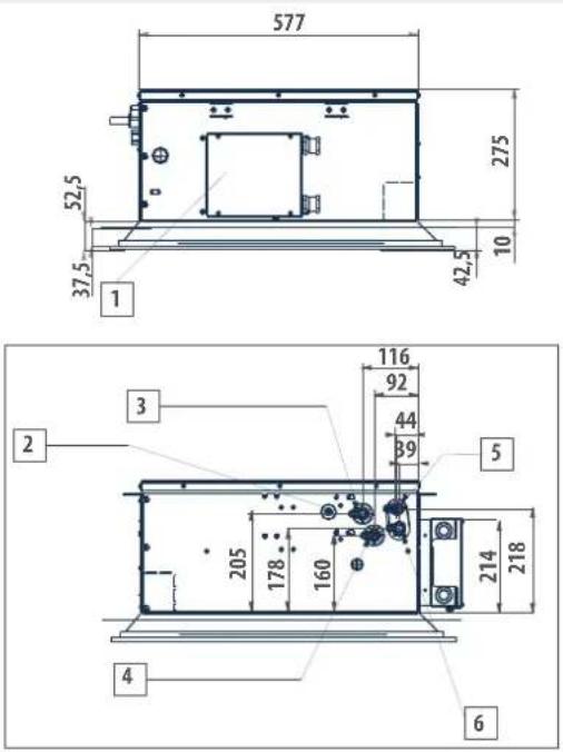
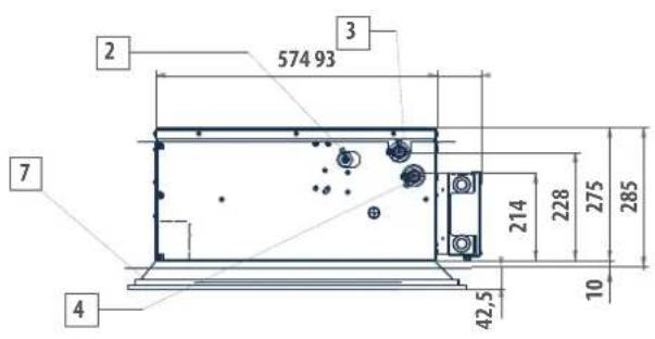
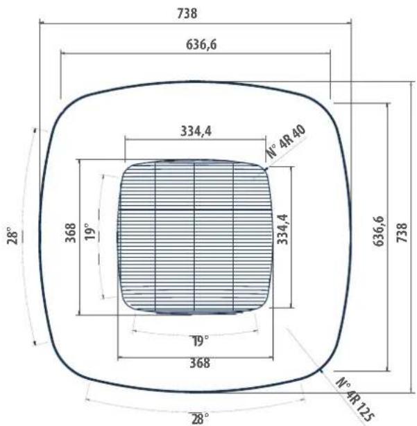
LEGENDA / VYSVĚTLIVKY / POJAŠNJENJE / LEGENDA
1)
Scatola elettrica / Electric box / Boitier électrique / Verteilungskasten / Caja conexiones eléctricas / Elektricsa skín / Lektríčna kutija / Curia electricá
2)
Scarico condensa o 10 / Condensate discharge o 10 / Purge des condensats o 10 / Kondenswasserablass o 10 / Descarga condensados o 10 / Odvod kondenzatu o 10 / Odvod kondenzata a 10 / Evacuarea condensului a 10
3)
Uscrita acqua scambiatore rafreddamento 1/2" gas F / Cooling exchanger water outlet, 1/2" gas F / Sortie eau échangeur rafračinissement 1/2" gaz F / Wasserauslass Kühlungwärmetauscher 1/2" BSP F / Salida agua intercambiador en inamiento 1/2" gas F / Výstup vody z chladčího výměnísu 1/2" plyn F / blaz vode iz izmjenjiváca hlađonja 1/2" plin F / lejire apá schimbátor de cálduřá rácie 1/2" gaz F
4)
Entrata acqua scambiatore raffreddamento 1/2" gas F / Cooling exchanger water inlet, 1/2" gas F / Entrée eau échangeur rafaîchissement 1/2" gaz F / Wassereinlass Kühlungswärmelbauscher 1/2" BSP F / Entrada agua intercambidor enñia miento 1/2" gas F / Příkod vody do chladicho výměníku 1/2" plyn F / Ulaž vode iz zmjenjivača hlađenja 1/2" pln F / Intare apá în schimbátor de rădire 1/2" gaz F
5)
Uscite aroque scambiatore riscaldamento 1/2" gas F / Healing exchanger water outlet, 1/2" gas F / Sortie eau échangeur chauffage 1/2" gaz F / Wasserauslass Heizungswármetauscher 1/2" DSP F / Salida agua intercambiador calentamiento 1/2" gas F / Výstup vody z topného výmóniku 1/2" plyn F / Izlaz vode izmijonjivača topline 1/2" plin F / lejiro apá schimbátor de cálduřa încálzire 1/2" gaz F
6)
Fnltrala acqua scambiatore fiscalamento 1/2" gas F / Heating exchanger water inlet, 1/2" gas F / Entree eau échangeur chauffage 1/2" gaz F / Wassereinlass Heizungswärmelanscher 1/2" BSP F / Entrada agua intercambiador catentamiento 1/2" gas F / Přívod vody do topného výméníku 1/2" plyn F / Ulaz vode izmjenjivača top line 1/2" plín F / Intraire apá schimbátor de čádurá 1/2" gaz F
The legend of following electrical wiring diagrams is on page: p. 45
» WC66000501 - FWI-A 02-08 with FWECSAP + modulating VALVE WIRING
» 13.13
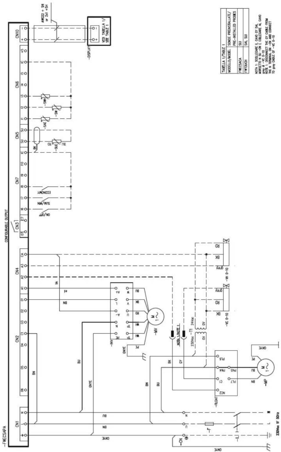
» 13.14
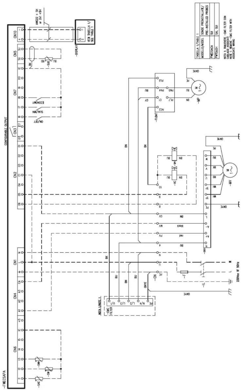
» 13.14

» 2-way valve kit - 2 pipes, FWI-A 02-03-04 / Kit vanne 2 voies - 2 tuyaux FWI-A 02-03-04 / 2-Wege-Ventilsatz - 2 Rohre FWI-A 02-03-04 / Kit de válvula de 2 vías - 2 tubos FWI-A 02-03-04 / Sada dvoucestného ventilu - 2 trubky FWI-A 02-03-04 / Komplet dvosmjernih ventila - 2 cijevi FWI-A 02-03-04 / Kit supapă cu 2 căi - 2 tevi FWI-A 02-03-04
» 13.15
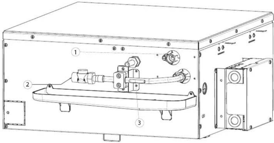
1)
Uscita acqua / Water outlet / Sortie d'eau / Auslass wasser / Salida de agua / Odvod vody / Izlaz voie / leşire apă
2)
Ingresso acqua /Water inlet / Enirée d'eau / Finlass wasser / Enirada de agua / Pivod vody / Ula/ vode / Intrare apà
3)
1)
Uscita acqua / Water outlet / Sortie d'eau / Auslass wasser / Salida de agua / Odvod vody / Izlaz vode / leşire apă
2)
Ingresso acqua /Water inlet / Enirée d'eau / Einlass wasser / Entrada de agua / Pôvod vody / Ulaz vode / Intrare apà
3)
1)
Uscita acqua fredda / Cold water outlet / Sortie d'eau froide / Kaltwasserauslass / Salida de agua fria / Odvod studenté vody / Izaz hladne vode / Iejire apä rece
2)
Ingresso acqua fredda / Cold water inlet / Entrée d'eau froide / Kaltwassereinlass / Entrada de agua tria / Přívod studené vody / Ulaz hladne vode / Intrare apá rece
3)
Jscita acqua calda / Hot water outlet / Sortie d'eau chaude / Warmwasserauslass / Salida de agua callente / Odvod toplé vody / Izlaz tople vode / leşire apă caldă
4)
Ingresso acqua calda / Hot water inlet / Entrée d'eau chaude / Waimwassereinlass / Entrada de aqua caliente / Pivod toplé vody / Ulaz tople vode / Intrare apà calda
5)
Porta sonde / Sensor holder / Port sonde / Wasserfühlerhalterung / Portasonda / Držák sondy / Kosač sonde / Suport sondá
NOTA: Gli attuatori non sono rappresentati. / NOTE: The actuators are not shown. / NOTE: les actionneurs ne sont pas representés. / HIRWLS: Die Stellantriebe sind nicht abgebildet. / NOTA: Los actuadores no están representados. / P07HÁMKA: Ačení Členy nejsou zastoupeny. / BILJESKA: Akkauatori nisu prikavani. / NOTA: Actuatoarele nu sunt reprezentace.
» KIt valvola 3 vie - 4 tubi FWI-A 02-04 / 3-way valve kit - 4 pipes, FWI-A 02-04 / Kit vanne 3 voies - 4 tuyaux FWI-A 02-04 / 3-Wege-Ventilsatz - 4 Rohre FWI-A 02-04 / Kit de válvula de 3 vías - 4 tubos FWI-A 02-04 / Sada trojcestného ventilu - 4 trubky FWI-A 02-04 / Komplet trosmjernih ventila - 4 cijevi FWI-A 02-04 / Kit supapă cu 3 căi - 4 tevi FWI-A 02-04
» 13.18

1)
Uscita acqua Fredda / Cold water outlet / Sortie d'eau froide / Kaltwasserauslass / Salida de agua fria / Odvod studené vody / Izlaz hladne vode / leşire apă rece
2)
Ingresso acqua fredda / Cold water inlet / Entrée d'eau froide / Kaltwassereinlass / Entrada de agua fria / Přívod studené vody / Ulaz hladne vode / Intrare apă rece
3)
Uscita acqua calda / Hot water outlet / Sortie d'eau chaude / Warmwasserauslass / Salida de agua caliente / Odvod leplé vody / Izlaz tople vode / legire apà caldă
4) Ingresso acqua calda / Hot water inlet / Entrée d'eau chaude / Warmwassereinlass / Entrada de agua caliente / Prívod teplé vody / Ulaz tople vode / Intrare apà calda
1)
Uscita acqua fredda / Cold water outlet / Sortie d'eau froide / Kaltwasserauslass / Salida de agua fria / Odvod studené vody / Iziaz hladne vode / leşire apã rece.
2)
Ingresso acqua frecuta / Cold water inlet / Entrée d'eau froide / Kaliwassere nlass / Entrada de agua fria / Pfixol studené vody / Ulaz hladne vode / Intrare apà rece
3)
Uscita acqua calda / Hot water outlet / Sortie d'eau chaude / Warmwasserauslass / Salida de agua caliente / Odvod toplé vody / Iziaz tople vode / les re apà calda
4)
Ingresso acqua calca / Hot water inlet / Entrée d'eau chaude / Warmwassereinlass / Entrada de agua caliente / Privod tepie vody / Ulaz tople vode / Intrare apă calda
5)
1)
Uscita acqua / Water outlet / Sortie d'eau / Auslass wasser / Salida de agua / Odvod vody / Izlaz voce / leşire apă
2)
Ingresso acqua /Water inlet / Ltrée d'eau / Linlass wasser / Ltrada de agua / Přivod vody / Ulaz voce / Intrare apá
3)
1)
Uscita acqua fredda / Cold water outlet / Sortie d'eau froide / Kaltwasserauslass / Salida de agua fria / Odvod studenté vody / Izaz hladne vode / Iejire apä rece
2)
Ingresso acqua fredda / Cold water inlet / Entrée d'eau froide / Kaltwassereinlass / Entrada de agua frila / Plivod studenté vody / Ulaz hladne vode / Intrare apá rece
3)
Uscla acqua calda / Hot water outlet / Sortie d'eau chaude / Warmwasserauslass / Salida de agua caliente / Odvod teplè vody / Izlaz tople vode / Ilesire aça caldā
4) Ingresso acqua calda / Hot water inlet / Entrée d'eau chaude / Warmwassercinlass / Entrada de aqua caliente / Plivod toplé vody / Ulaz tople vode / Intrare apà calda
5) Porta sonde / Sensor holder / Port sonde / Wasserfühlerhalterung / Portasonda / Držák sondy / Kosač sonde / Suport sondá
NOTA: Gli attuatori non sono rappresentati. / NOTE: The actuators are not shown. / NOTE: les actionneurs ne sont pas representés. / HIRWLS: Die Stellantriebe sind nicht abgebildet. / NOTA: Los actuadores no están representados. / P07HÁMKA: Ačení Členy nejsou zastoupeny. / BILJESKA: Akkauatori nisu prikavani. / NOTA: Actuatoarele nu sunt reprezentace.
» Kit valvola 3 vie - 2 tubi FWI-A 06-07-08 / 3-way valve kit - 2 pipes, FWI-A 06-07-08 / Kit vanne 3 voies - 2 tuyaux FWI-A 06-07-08 / 3-Wege-Ventilsatz - 2 Rohre FWI-A 06-07-08 / Kit de válvula de 3 vías - 2 tubos FWI-A 06-07-08 / Sada trojcestného ventilu - 2 trubky FWI-A 06-07-08 / Komplet trosmjernih ventila - 2 cijevi FWI-A 06-07-08 / Kit de supapă cu 3 căi - 2 tevi FWI-A 06-07-08
» 13.22
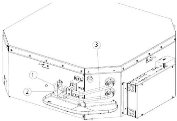
1) Uscita acqua / Water outlet / Sortie d'eau / Auslass wasser / Salicia de agua / Odvod vody / Izlar vode / leşire apà 2)
Ingresso acqua / Water inlet / Entrée d'eau / Einlass wasser / Entrada de agua / Privod vody / Uiaz vode / Intrare apà 3)
Porta sonda / Sensor holder / Port sonde / 'Wasserfühlerhaiterung / Portasonda / Držák sondy / Nosač sonde / Suport sondá
NOTA: Cattualore non è rappresentato. / NOTE: The actuator is not shown. / NOTE: l'action neur n'est pas représenté. / HINWEIS: Der Stellantrico ist nicht abgebildet. / NOTE: El actuador no está representado. / POZNÁMKA: Akóni čen mení zastoupen. / BLUESKA: Aktuator nije prikazan. / NOTA: Actuatorul nu este prezentat.
» Kit valvola E2C2PIC/PRP; E4C2PIC 2 vie - 2 tubi FWI-A 02-03-04 / 2-way E2C2PIC/PRP; E4C2PIC valve kit - 2 pipes, FWI-A 02-03-04 / Kit vanne E2C2PIC/PRP; E4C2PIC 2 voies - 2 tuyaux FWI-A 02-03-04 / 2-Wege-Ventilsatz E2C2PIC/PRP; E4C2PIC - 2 Rohre FWI-A 02-03-04 / Kit de válvula E2C2PIC/PRP; E4C2PIC de 2 vías - 2 tubos FWI-A 02-03-04 / Sada ventilu E2C2PIC/PRP; E4C2PIC dvoucestný - 2 trubky FWI-A 02-03-04 / Komplet ventila E2C2PIC/PRP; E4C2PIC dvosmjerní - 2 cijevi FWI-A 02-03-04 / Kit de supape E2C2PIC/PRP; E4C2PIC cu 2 căi - 2 tevi FWI-A 02-03-04
» 13.23
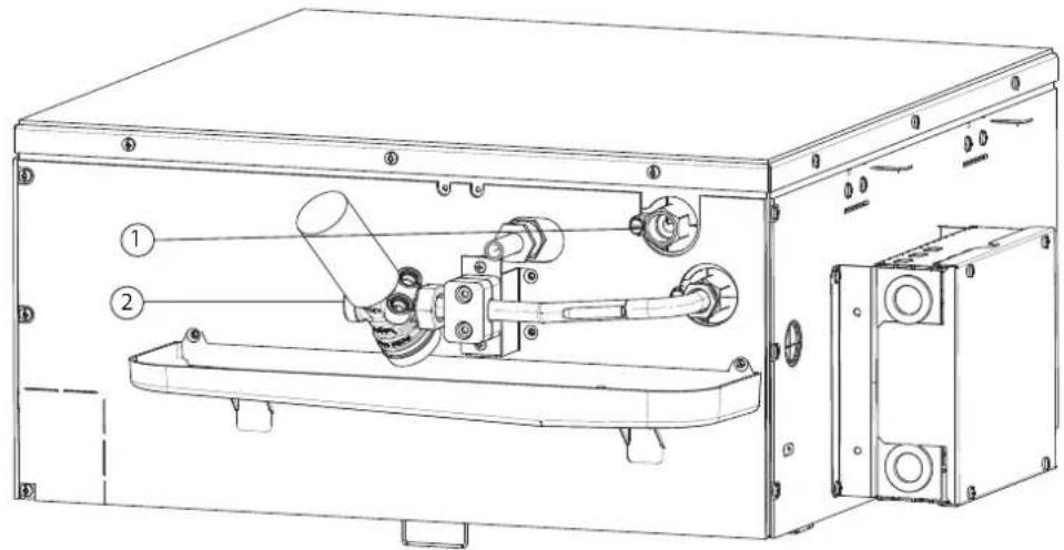
1)
Uscita acqua / Water outlet / Sortie d'eau / Auslass wasser / Salida de agua / Odvod vody / Izlaz vode / lesire apa
2)
Ingresso acqua / Water inlet / Entrée d'eau / Einlass wasser / Entrada de agua / Odvod vody / Ullaz vode / Intrare apà
» Kit valvola E2C2PIC/PRP; E4C2PIC/PRP- 2 vie - 4 tubi FWI-A 02-04 /2-way valve kit E2C2PIC/PRP; E4C2PIC/PRP - 4 pipes, FWI-A 02-04 /Kit vanne E2C2PIC/PRP; E4C2PIC/PRP 2 voies - 4 tuyaux FWI-A 02-04 /E2C2PIC/PRP; E4C2PIC/PRP 2-Wege-Ventilsatz - 4 Rohre FWI-A 02-04 /Kit de válvula E2C2PIC/PRP; E4C2PIC/PRP de 2 vias - 2 tubos FWI-A 02-04 / Sada ventilu E2C2PIC/PRP; E4C2PIC/PRP- dvoucestný - 4 trubky FWI-A 02-04 / Komplet ventila E2C2PIC/PRP; E4C2PIC/PRP- dvosmjerni - 4 cijevi FWI-A 02-04 / Kit de supape E2C2PIC/PRP; E4C2PIC/PRP cu 2 căi - 4 tevi FWI-A 02-04
» 13.24
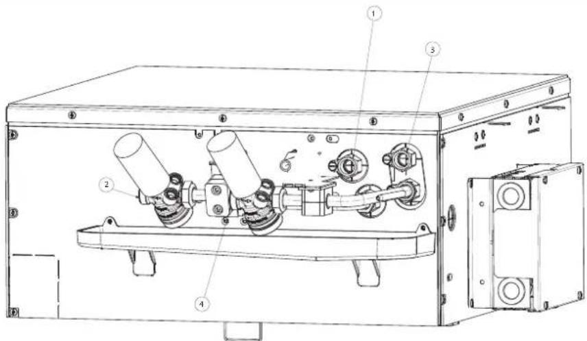
1)
Uscita acqua fredda / Cold water outlet / Sortie d'eau froide / Kaltwasserauslass / Salicia de agua fria / Odvod studené vody / Izaz hladne vode / Ieşire apà rece
2)
ingresso acqua fredda / Cold water inlet / Entrée deau froide / Kaltwassereinlass / Ltrada de agua fria / Přivod studené vody / Ulaz hladne vode / Intrare apá rece
3)
Uscita acqua calda / Hot water outlet / Sortie d'eau chaude / Warmwasserauslass / Salida de agua caliente / Odvod toplé vody / Izlaz toplé vode / leşire apă calda
4)
Ingresso acqua calda / Hot water inlet / Entrée d'eau chaude / Wammwassereinlass / Entrada de agua caliente / Pilved teplé vody / Ulaz tople vode / Intrare apà calda
» Kit valvola E2C2PIC/PRP; E4C2PIC/PRP 2 vie - 2 tubi FWI-A 06-07-08 / 2-way E2C2PIC/PRP; E4C2PIC/PRP valve kit - 2 pipes, FWI-A 06-07-08 / Kit vanne E2C2PIC/PRP; E4C2PIC/PRP 2 voies - 2 tuyaux FWI-A 06-07-08 / 2-Wege-Ventilsatz E2C2PIC/PRP; E4C2PIC/PRP - 2 Rohre FWI-A 06-07-08 / Kit de válvula E2C2PIC/PRP; E4C2PIC/PRP de 2 vías - 2 tubos FWI-A 06-07-08 / Sada ventilu E2C2PIC/PRP; E4C2PIC/PRP dvoucestný - 2 trubky FWI-A 06-07-08 / Komplet ventila E2C2PIC/PRP; E4C2PIC/PRP dvo-smjerni - 2 cijevi FWI-A 06-07-08 / Kit de supape E2C2PIC/PRP; E4C2PIC/PRP cu 2 cǎi - 2 tevi FWI-A 06-07-08
» 13.25
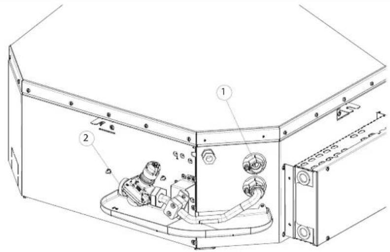
1)
Uscita acqua / Water outlet / Sortie d'eau / Auslass wasser / Salica de aqua / Odvod vody / Iziaz vode / leşire apà
2)
Ingresso acqua / Water inlet / Entrée d'eau / Einlass wasser / Entrada de agua / Odvod vody / Uiaz vode / Intrare apé
Kit valvola E2C2PIC/PRP; E4C2PIC/PRP 2 vie - 4 tubi FWI-A 06-08 / 2-way valve kit E2C2PIC/PRP; E4C2PIC/PRP - 4 pipes, FWI-A 06-08 / Kit vanne E2C2PIC/PRP; E4C2PIC/PRP 2 voies - 4 tuyaux FWI-A 06-08 / E2C2PIC/PRP; E4C2PIC/PRP 2-Wege-Ventilsatz - 4 Rohre FWI-A 06-08 / Kit de válvula E2C2PIC/PRP; E4C2PIC/PRP de 2 vías - 4 tubos FWI-A 06-08 / Sada ventilu E2C2PIC/PRP; E4C2PIC/PRP dvoucestný - 4 trubky FWI-A 06-08 / Komplet ventila E2C2PIC/PRP; E4C2PIC/PRP dvosmjerni - 4 cijevi FWI-A 06-08 / Kit de supape E2C2PIC/PRP; E4C2PIC/PRP cu 2 cǎi - 4 čevi FWI-A 06-08
» 13.26
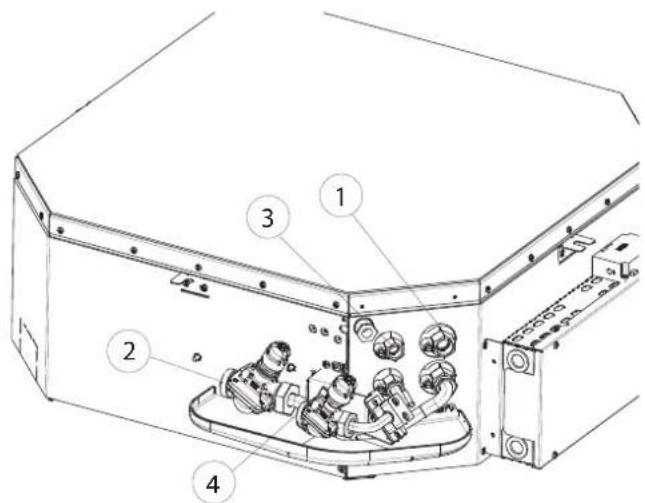
1)
Uscita acqua fredda / Cold water outlet / Sortie d'eau froide / Kaltwasserauslass / Salida de agua fria / Odvod studené vody / Izlaz hladne vode / Iesire apä rece
2)
Ingresso acqua fredda / Cold water inlet / Entrée d'eau froide / Kaltwassereinlass / Entrada de agua fria / Privod studené vody / Ulaz hladne vode / Intrare apà rece
3)
Uscita acqua calda / Hot water outlet / Sortie d'eau chaude / Warmwasserauslass / Salida de agua caliente / Odvod teplé vody / Izaz tople vode / leşire apă caldă
4)
Ingresso acqua calda / Hot water inlet / Enrée d'eau chaude / Warmwassereinlass / Ltrada de agua calienne / Přivod toplé vody / U'az tople vode / Intrare apă caldă
DAIKIN
- DAIKIN
- Restriction of Certain Hazardous Substances in electrical and electronic equipment
- UKCA – Safety declaration of conformity
- Daikin Europe N.V.
- UKCA – Ecodesign declaration of conformity
- Airconditioning (EU) 2016/2281
- UKCA – RoHS declaration of conformity
- Comando dedicato (FWEC10 - FWECSA - FWEC3A)
- METTERE L'UNITÀ IN TENSIONE
- COLLEGAMENTO MANDATA ARIA IN LOCALI ATTIGUI
- MANUTENZIONE
- PULIZIA DEL FILTRO ARIA GRIGLIA FCND02A
- LIVELLO ACQUA ANOMALO
- RICERCA DEI GUASTI
- SAFETY SYMBOLS
- INTENDED USE
- INSTALLATION SITE
- OPERATING LIMITS
- UNIT DESCRIPTION
- Comfort, low noise, and efficiency in perfect harmony!
- AVAILABLE VERSIONS
- Accessories supplied with the unit
- MAINCOMPONENTS
- Structure
- Airfilter
- Heatexchanger
- Fan drive assembly
- Condensate collection system
- Condensate discharge system
- FPANGrille
- FCND02A grille: design grille with Coandă eff ect
- ACCESSORIES
- DIMENSIONS
- INSTALLATION
- INSTALLATION REQUIREMENTS
- WARNING:
- Electrical connections
- Control dedicated (FWEC10 - FWECSA - FWEC3A)
- Condensate drain connection
- DIMENSIONAL UNIT ASSEMBLY
- Front panel/FPAN grille assembly
- To install the front panel: (Fig.12)
- Front panel/grille FCND02A assembly
- CHECKS BEFORE STARTUP
- PRELIMINARY CHECKS
- Make sure:
- SWITCH ON THE UNIT
- FILL THE WATER CIRCUIT
- ADJUSTING THE AIR FLOW (FPAN ONLY)
- 7USE
- 8ACCESSORIES
- 2- OR 3-WAY MOTOR-DRIVEN VALVE KITS
- PRESSURE-INDEPENDENT MOTOR-DRIVEN 2-WAY VALVE KIT
- AUXILIARY WATER DRIP TRAY FOR COLLECTING CONDENSATE FROM THE CONTROL VALVES
- CONNECTION FOR INTAKE OF FRESH AIR TO BE TREATED
- CONNECTION FOR OUTLET OF AIR IN ADJACENT ROOMS
- DANGER!
- CLEANING THE AIR FILTER GRILLE FPAN
- CLEANING THE AIR INTAKE GRILLE FPAN
- CLEANING THE AIR FILTER FCND02A GRILLE
- CLEANING OF FCND02A GRILL COVER PANEL
- ELECTRIC CONTROL BOARD
- ADDITIONAL MAINTENANCE
- ABNORMAL WATER LEVEL
- TROUBLESHOOTING
- RATED TECHNICAL DATA
- ELECTRICAL WIRING DIAGRAM LEGEND
- The electrical connections indicated must be made by the installer
- ADDITIONAL CONNECTION FOR FWECSA
- VERSIONS DISPONIBLES
- MONTAGE UNITÉS À L'AIDE DES SCHÉMAS DIMENSIONNELS
- Montage panneau frontal/grille FPAN
- Montage panneau frontal/grille FCND02A
- VÉRIFICATION FONCTIONNELLE
- CONTRÔLES PRÉALABLES
- S'assurer :
- RACCORDEMENT DE REFOULEMENT D'AIR DANS DES PIÈCES ATTENANTES
- 9ENTRETIEN
- NETTOYAGE GRILLE D'ASPIRATION FPAN
- NETTOYAGE DU FILTRE À AIR GRILLE FCND02A
- NETTOYAGE DU LE PANNEU DU FILTRE À AIR GRILLE FCND02A
- Montage des Frontpaneels/des FPAN Gitters
- Montage de Frontpaneel/de FCND02A Gitter
- VORABKONTROLLEN
- Sich vergewissern:
- ANGETRIEBENER 2-WEGE-VENTILSATZ PRESSURE INDEPENDENT
- 9WARTUNG
- REINIGUNG DES ANSAUGGITTERS
- REINIGUNG DES LUFTFILTERS FCND02A GITTER
- ANORMALER WASSERSTAND
- Rejilla FCND02A: rejilla de design con efecto Coandă
- ACCESORIOS
- MONTAJE DE LA UNIDAD
- Para instalar el frente: (Fig.12)
- MANTENIMIENTO
- LIMPIEZA DEL FILTRO DE AIRE REJILLA FCND02A
- LIMPIEZA DEL PANEL DE CIERRE DE LA REJILLA FCND02A
- NIVEL ANÓMALO DE AGUA
- MONTÁŽ ROZMĚROVÝCH JEDNOTEK
- FUNKČNÍ KONTROLA
- PŘEDBĚŽNÉ KONTROLY
- Ujistěte se:
- PŘIPOJENÍ PŘÍVODU VZDUCHU V SOUSEDNÍCH MÍSTNOSTECH
- 9ÚDRŽBA
- Č IŠTĚNÍ MŘÍŽKY VZDUCHOVÉHO FILTRU FCND02A
- ČIŠTĚNÍ UZAVÍRACÍHO PANELU MŘÍŽKY FCND02A
- ABNORMÁLNÍ HLADINA VODY
- Rešetka: dizajnerska rešetka s Coandă efektom FCND02A
- PODATCI O DIMENZIJAMA
- UGRADNJA
- Namjenska naredba (FWEC10 - FWECSA - FWEC3A)
- MONTAŽA DIMENZIJSKIH JEDINICA
- Montaža prednje strane/rešetke FCND02A
- PRIKLJUČAK ZA USIS PRIMARNOG ZRAKA KOJI TREBA TRETIRATI
- PRIKLJUČAK ZA DOVOD ZRAKA U SUSJEDNE PROSTORIJE
- 9ODRŽAVANJE
- ČIŠĆENJE FPAN USISNE REŠETKE
- ČIŠĆENJE FILTRA ZRAKA REŠETKE FCND02A
- ČIŠĆENJE PLOČE ZA ZATVARANJE REŠETKE FCND02A
- 9.5ELEKTRIČNIORMAR
- DODATNO ODRŽAVANJE
- NEDOZVOLJENA RAZINA VODE
- RJEŠAVANJE KVAROVA
- MONTAREA UNITĂȚILOR DIMENSIONALE
- VERIFICARE FUNCTIONALĂ
- CONTROALE PRELIMINARE
- Asigurati-vă că:
- RACORDUL DE ALIMENTARE CU AER ÎN ÎNCĂPERI ADIACENTE
- ÎNTRETINERE
- CURĂȚAREA GRILEI DE ADMISIE FPAN
- CURĂȚAREA FILTRULUI DE AER AL GRILEI FCND02A
- CURĂTAREA CAPACULUI GRILEI FCND02A
- NIVEL ANORMAL AL APEI
- LEGENDA / LEGEND / LÉGENDE / LEGENDE / LEYENDA / VYSVĚTLIVKY / POJAŠNJENJE / LEGENDA
- LEGENDA / VYSVĚTLIVKY / POJAŠNJENJE / LEGENDA
- 1)
- 2)
- 3)
- 4)
- 5)
Brand : DAIKIN
Model : FWI06AAT
Category : Air Conditioning