
FWP11CAFN6V3 - Air Conditioning DAIKIN - Free user manual and instructions
Find the device manual for free FWP11CAFN6V3 DAIKIN in PDF.


User questions about FWP11CAFN6V3 DAIKIN
0 question about this device. Answer the ones you know or ask your own.
Ask a new question about this device
Download the instructions for your Air Conditioning in PDF format for free! Find your manual FWP11CAFN6V3 - DAIKIN and take your electronic device back in hand. On this page are published all the documents necessary for the use of your device. FWP11CAFN6V3 by DAIKIN.
USER MANUAL FWP11CAFN6V3 DAIKIN
natural_image
Interior view of an open industrial air duct with exposed panel and wiring (no text or symbols visible)CE
| CE - DECLARATION-OF-CONFORMITYCE - KONFORMITÄTSEKARLARUNGCE - DECLARATION-DE-CONFORMITECE - CONFORMITEITSVERKLARING | CE - DECLARACION-DE-CONFORMIDACE - DICHIARAZIONE-DI-CONFORMITACE - ΔΗΔΩΣΗ ΣΥΜΜΟΡΦΩΣΗΣ | CE - DECLARAÇÃO-DE-CONFORMIDADECE - ЗАRBЛЕНИЕ-О-СООТВЕТСТВИENCE - ÖVERENSTSEMMELESESERKLÆRINGCE - FÖRSAKRAN-OM-ÖVERENSTÄMMELSE | CE - ERKLÆRING ON-SAMSVARCE - ILMOITUS-YHĐENIMUKAISUDESTACE - PROHLŠEN-I-O-SHODE | CE - IZJAVA-O-USKLADENOSTICE - MEGFELELOSÉGI-NYILATKOZATCE - DEKLARACJA-ZGODNÓSICCE - DECLARAÎE-DE-CONFORMITATE | CE - IZJAVA O SKLADNOSTICE - VASTAVUSDEKLARATSIOONCE - ДЕКЛАРАЦИЯ-3A-СЪОТВЕТСТВИЕ | CE - ATTITIKTIES-DEKLARACIJACE - ATBILSTÍBAS-DEKLARÁCIJACE - VYHŁASENIE-ZHODYCE - UYGUNLUK-BEYANI |
| Daikin Europe N.V. | ||||||
| 01 ⬆ cecares under its sole responsibility that the air conditioning models to which this declaration relates:02 ⬇ erklart auf seine allanige Verantwortung daß die Modello cer Klimseráze für die deze Erfindung bestimmit ist:03 ⬇ cecare sus se seule responsašité que les appareils c'ar conditionné visés par la presente déclaration:04 ⬇ verkraart hříbj op eben exclusiva verantwortedljedníkići cat de alconditioning units wearoo ceze verdaring betrekking heeft:05 ⬇ cecara baja su única responsabilidad que los modelos de are accondorado i los cuales hace referencia a declaración:06 ⬇ dichlara sotto sua responsašité che i pondonadorii modelo a cui è rifiila questa dicharazione:07 ⬇ Šnăžuje je (atrockizemt) ring ečevn óm ra povstala ruv svupomirkov sputesuvi ote etede ovojpetron i npoćoča 5jtkuwon:08 ⬇ cecara sub sua exclusiva responsabilidade que os modelos de ar condicionado a que esta declaração se refere: | 09 ⬇ zastatelet, velickintėtyno pod suo ответственность, tho vođetni oncočruvovere boudyka, i komporiu oniodorita nastosušće zastateleve:10 ⬇ erklarer und anseaner, at klimaanlagmodelame, som denne deklaration vedrerer:11 ⬇ daflarari i egenskap av huvčanswarg, att utlikonditioningsmocelerna som bintis av denna deklaration innesdár att:12 ⬇ erklarer et fulžendig aner for at de utlikondiseningersmodefer som berares av denne desklaracion, inneberer at:13 ⬇ limotlas yssinoman ovalla vastudean, etlia tāmīn ilholuisan tarkolitanas. lmasitoriābililaien malit:14 ⬇ prohlásuje na své aine odpovedností, ze motely klimazace, ki mīz se za promlašeni vztahujá:15 ⬇ izjavluje peol iskljušivo vlastnom odgovornočtu da su modeli klima urečajá na kope sa ova izjava cnosit:16 ⬇ tejes felečsége tudarčion kijeleri, hogy a klimaberendezais modellek, meysere e rylatkizat vonalnikozik: | 17 ⬇ cekaruje na wlesna i wyłeczna odpowiedzišnost, że modele klimatyzabów, których dotyczy niejsza deklaracja:18 ⬇ cecará pe opronie raspondere sa aparazola do aer condijonal ie care se rofará aceasla declaraje:19 ⬇ z vsa odgovornoste tibavlje, da so modeli klimatskih raprev, na katere se izjava nanalja:20 ⬇ kinitiato oma tāilekil uvatustus, et kaiesleva okratatsbori alla tuvalud klimaseoctrete mudsid:21 ⬇ deznaporce na osos tõvskorckci, ne kooperte klimatestnica instala pen, ze kotto se otknava taam ārspaparačen:22 ⬇ vislěka savo elaskaromyce skolbja, kad ora konidcionalno pretalsa imdatai, kurme yra lakoma ši deklaracija:23 ⬇ ar sihu abitičbe aplicnca, ka tālār izskaitite modeu gaisa klonidantij, au kurum attilcas šī deklaracija:24 ⬇ vyljasuje na vlastna zojopevchod, že lišio klimatizaneč modedy, na itóné sa vizfahuje tovo vylhlasire:25 ⬇ tamamen kendi sorumlutjunda omak izvare bu bidrimin itgii odlugu klima modelamin apojodiaki gibi odluğunu beyan ecker: | ||||
| FWP04CAT*6V3***, FWP05CAT*6V3***, FWP06CAT*6V3***, FWP08CAT*6V3***, FWP08CAF*6V3***, FWP05CAF*6V3***, FWP06CAF*6V3***, FWP08CAF*6V3***, FWP08CAG*6V3***, FWP06CAG*6V3***, FWP08CAG*6V3***, FWP08CAG*6V3***, FWP08CAG*6V3***, FWP08CAG*6V3***, FWP08CAG*6V3***, FWP08CAG*6V3***, FWP08CAG*6V3***, FWP08CAG*6V3***, FWP08CAG* 6V3***, FWP08CAG*6V3***, FWP08CAG*6V3***, FWP08CAG*6V3***, FWP08CAG*6V3***, FWP08CAG*6V3***, FWP08CAG*6V3***, FWP08CAG*6V3***, FWP08CAG*6V3** | ||||||
Ostend, 14th of December 2020
DAIKIN EUROPE N.V.
Thermal carrier fluid: water
Water temperature: 5 °C ÷ 90 °C
Air temperature: -20 °C ÷ 40 °C
Control voltage: 230 V
Maximum operating pressure: 16 bar
Limit of room air relative humidity: RH<85% not
condensing
1 BEFORE STARTING THE INSTALLATION PROCEDURE
Carefully read this manual.
Installation and maintenance should be carried out by technical personnel qualified for this type of machine, in compliance with current safety regulations.
When receiving the unit please check its state verifying if any
damage occurred during the transport.
For installation and use of accessories, please refer to the relative technical sheets.
Identify the model of the FWP-C fan coil following the indications on the packing container.
SAFETY SYMBOLS

Carefully read this manual.

Warning

Use personal protective equipment
USE SUITABLE PPE (GLOVES FOR REFRIGERANT, PROTECTIVE GOGGLES)
authorized installer and must comply with applicable legislation. Units must be treated at a specialized treatment facility for reuse, recycling and recovery. By ensuring this product is disposed of correctly, you will help to prevent potential negative consequences for the environment and human health. For more information, contact your installer or local authority.
ATTENTION: the unit hasn't dangerous components according to the classification of Regulation 1357/2014.
WARNING: Electrical and electronic products may not be mixed with unsorted household waste. Do NOT try to dismantle the system yourself: the dismantling of the system, treatment of oil and of other parts must be done by an
2 INTENDED USE
Daikin will not accept any liability for damage or injury caused as a result of installation by non-qualified personnel; improper use or use in conditions not allowed by the manufacturer; failure to perform the maintenance prescribed in this manual; use of spare
parts other than original factory parts.
Equipment designed for ambient air conditioning and intended for use in civil comfort applications.
INSTALLATION SITE
When choosing an installation site, you should observe the following rules:
— The air conditioning unit should not be placed immediately under a socket
— Do not install the unit in places where inflammable gases or powders are present
— Do not expose the unit to sprays of water; do not install the
unit in laundry room
— Install the fan coil on walls or ceilings able to withstand its weight. Keep a clear space all around the unit to assure the proper functioning and accessibility for maintenance
— Store the unit in its packing container until you are ready to install it to prevent dust from infiltrating inside it.
3 UNIT DESCRIPTION
MODULATION AND EFFICIENCY IN A RECESS CEILING-MOUNTED UNIT
The range is completed by FWP-C, which uses inverter EC technology in the electric motors. To the features of FWP-C adds the benefits of brushless technology, including a reduction in electricity consumption and consequent reduction in CO_2 emissions, increase in operating flexibility thanks to the modulation of air flow and increase in the level of comfort in terms of temperature, humidity and noise levels.
The range is made up of 8 models with air flows from 300 to 1200 m ^3 /h.
Continuous modulation of the air flow and the use of high-efficiency heat exchangers enables operation also with small air-water temperature differences.
The heat exchangers can also be optimized in the circuit for centralized applications such as district cooling.
MAIN COMPONENTS
Structure
Built from galvanised steel sheet, heat and sound insulated by means of Class 1 self-extinguishing panels. Reduced height to facilitate installation in a horizontal position in a false ceiling. The structure incorporates a drip tray and condensate drain outlet. The main condensate drip tray is situated inside the structure of the unit and is at a positive pressure relative to the drain outlet to facilitate condensate drainage.
Heat exchanger
High efficiency standard with 3 rows, but also available with 4 rows upon request, heat exchanger made with copper piping and aluminium fins blocked to pipings by mechanical expansion, provided with brass manifolds and air vent valve. The heat exchanger usually comes with water connections mounted on the left, but it can be turned by 180°. High-efficiency heat exchangers optimized for district cooling applications are available on request.
Fans
Double suction centrifugal fans made with ABS or aluminium, with statically and dynamically balanced forward-curving blades, directly coupled to the electric motor.
EC motor
Permanent magnet motor the unit is equipped with an inverter board to control the motor, that makes it possible to precisely set the maximum rotation speed (control signal 0-10 V).
Air filter
Washable air filter, made of acrylic fibre, filtration class G3, applied on the air intake; may be pulled out from below.
Air intake
Air intake from the front or bottom of the unit, according to system requirements.
Installation example
The bearing structure allows to combine a large range of accessories in suction and air delivery in order to obtain the optimized unit configuration.
ACCESSORIES
| Electronic microprocessor control panels with display | |
| FWECSAP | Circuit board for FWECS control |
| FWECSAC | User interface with display for FWECS controller |
| FWEC3AA | FWEC3AA electronic controller with display |
| FWHSKA | Humidity sensor for FWEC3AA, FWECS |
| FWTSKA | Water sensor for FWEC3AA and FWECS controllers |
| Auxiliary water drip trays, insulating shell, condensate drainage pump | |
| CDRP1A Condensate drainage pump kit | |
| Electrical heating elements | |
| EH Heating element with installation kit, relay box and safety devices | |
| EPIMSB6 Power interface for connecting in parallel up to 4 fan coil units to the one controller | |
| EDPD Auxiliary water drip tray | |
| Valves | |
| 2-way valves, ON/OFF or MODULATING actuator, 230 V or 24 V power supply, hydraulic kit, for additional heat exchanger | |
| 2-way valve, ON/OFF or MODULATING actuator, 230 V or 24 V power supply, hydraulic kit, for main heat exchanger | |
| 3-way valves, ON/OFF or MODULATING actuator, 230 V or 24 V power supply, hydraulic kit, for additional heat exchanger | |
| 3-way valves, ON/OFF or MODULATING actuator, 230 V or 24 V power supply, hydraulic kit, for main heat exchanger | |
| 2-way valves pressure independent, ON/OFF or MODULATING actuator, 230 V or 24 V power supply, hydraulic kit, for main and additional heat exchanger | |
Figure p. 82-83 Dimension shows FWP-C dimensional data and position of plumbing connections.
5 INSTALLATION
WARNING: unit installation and start-up must be entrusted to competent personnel and performed in a workmanlike manner, in accordance with current regulations.
⚠ WARNING: Install the ducted unit, the line switch (IL) and/or all remote controls in a position out of the reach of persons who are in the bathroom or in the shower.
IMPORTANT: It is advisable to install any accessories on the standard unit prior to positioning the latter, making reference to the technical sheets. The air intake and outlet have a rectangular cross-section, with pre-cut holes for fastening
the available accessories.
The exchanger connections can be switched over to the opposite side by carrying out the following steps (p. 84 Exchanger connections):
— remove the upper closing panel.
— remove the collecting condensate tray.
— remove the heat exchanger module by taking out the fastening screws (2 per side).
— turn the heat exchanger by 180^ (on the vertical axis) and screw it back into the unit again.
— reassemble the tray and the upper closing panel.
INSTALLATION REQUIREMENTS
Some rules to follow
—Vent air from the exchanger while the pumps are off. For this purpose use the air vent valves situated next to the exchanger connections.
— All ducts, especially the outlet ducts, must be insulated with anti-condensation material.
— An inspection panel must be provided in proximity to the unit to enable maintenance and cleaning operations.
— The unit must be installed on the basis of design and technical considerations, carrying out an aeraulic assessment and considering the BACK PRESSURE offered by the PIPING applied to the outlet to avoid the problem of failure to change speed: this responsibility cannot fall on the product but on the installation;
— Install the unit with the appropriate inspection hatches for routine and special maintenance of the fan coils: for mechanical, electrical and hydraulic replacement;
— Install the control panel on the wall; choose an accessible position from where functions may be easily set and which is suitable for taking temperature readings, where applicable. Avoid positions directly exposed to sunlight or direct currents of hot or cold air and make sure there are no obstacles which may preclude a correct temperature reading.
WARNING:
In normal operation, particularly with the fan at minimum speed and ambient air with high relative humidity, condensation may form on the air outlet and on some external parts of the unit.
To avoid such issues while always remaining within the operating limits envisaged for the unit, it is necessary to limit the inlet temperature of the water inside the heat exchanger. In particular, the difference between the air dew point ( T_A, D_P ) and the inlet water temperature ( T_W ) must NOT exceed 14 °C, according to the following relationship: TW>TA, DP-14 °C
Example: in the case of ambient air at 25^ C with 75% relative humidity, the dew point temperature is about 20^ C and therefore the inlet temperature of the water in the battery must be greater then:
— 20-14 = 6 °C in order to avoid condensation on a fancoil equipped with a valve.
— 20-12 = 8 °C If the valve kit accessory can not be installed.
| Fan coil with valve | ||||||||
| Air temperature dry bulb (°C) | ||||||||
| 21 23 | 25 27 | 29 31 | 33 | |||||
| Relative humidity % | 40 55 | 55555 | ||||||
| 50 55 | 55568 | |||||||
| 60 55 | 557911 | |||||||
| 70 55 | 6891113 | |||||||
| 80 56 | 810121416 | |||||||
| 90 68 | 1012141618 | |||||||
| Fan coil without valve | ||||||||
| Air temperature dry bulb (°C) | ||||||||
| 21 23 | 25 27 | 29 31 | 33 | |||||
| Relative humidity % | 40 66 | 66666 | ||||||
| 50 66 | 666810 | |||||||
| 60 66 | 6791113 | |||||||
| 70 66 | 810111315 | |||||||
| 80 68 | 1012121618 | |||||||
| 90 810 | 1214141820 | |||||||
In the event the indoor unit is stopped for a prolonged period, with the fan stopped and circulation of cold water in the heat exchanger, condensation may also form on the unit's exterior. In this case it is advisable to install the 3-way (or 2-way) valve accessory in order to stop the flow of water in the coil when the fan is stopped.
During wintertime periods of shut down, drain water from the system, to prevent ice from forming. If anti-freeze solutions are used, check for their freezing point using the table below.
| % Glycol by weight | Freezing temperature (°C) | Capacity adjustment | Pressure drop adjustment |
| 0 0 1,00 1,00 | |||
| 10 | -4 | 0,97 1,05 | |
| 20 | -10 | 0,92 1,10 | |
| 30 | -16 | 0,87 1,15 | |
| 40 | -24 | 0,82 1,20 |
Electrical connections
Make the electrical connections with the power supply disconnected, in accordance with current safety regulations.
All the wiring must be done by qualified personnel.
For each thermal ventilating unit provide a main circuit breaker (IL), with opening contacts separated by at least 3 mm and an adequate protection fuse (F).
Electrical intakes are shown on the rating labels on the units.
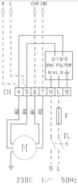
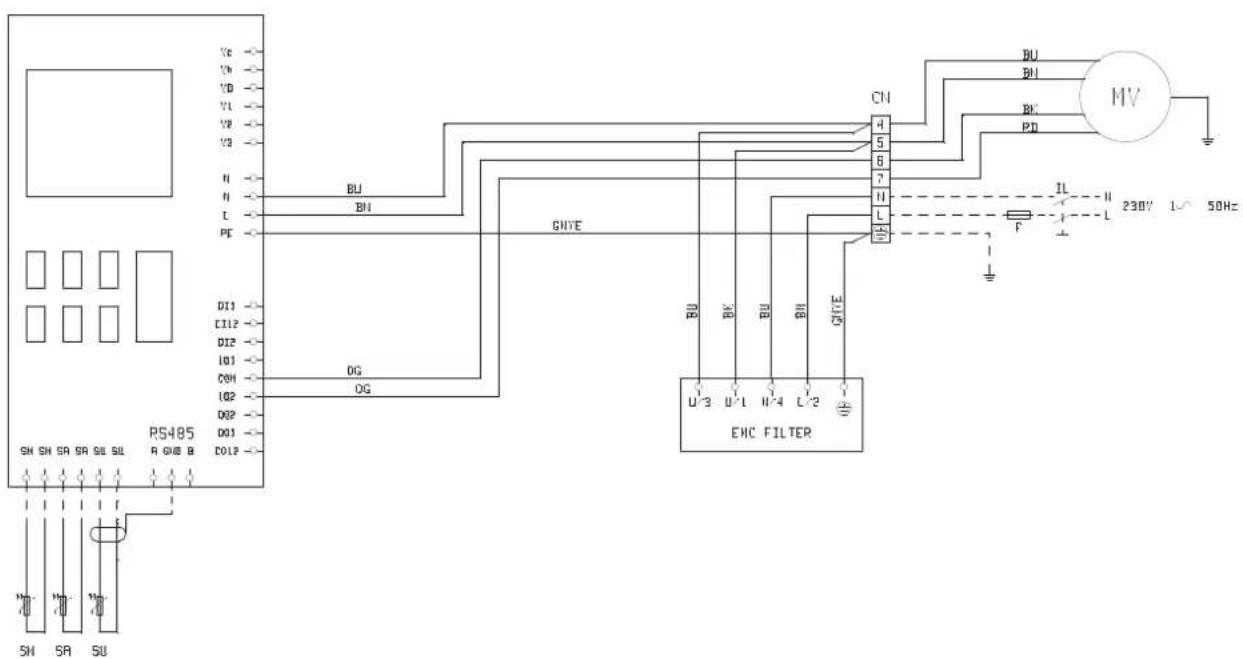
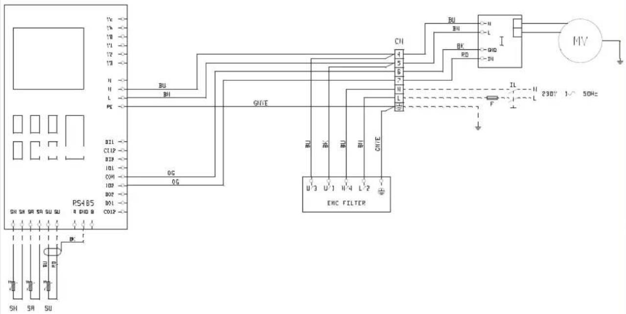
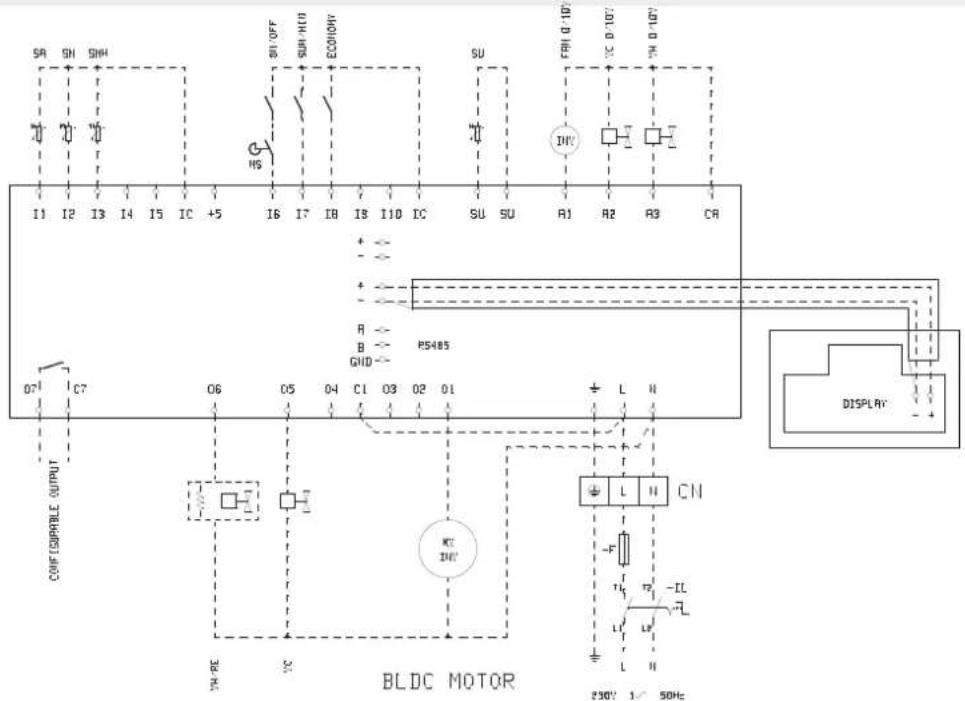
During installation, strictly abide by the indications on the wiring diagram for the unit-control panel combination.
FWP-C + FWEC3A (built-in) p. 86
FWP-C + FWEC3A (separate motor) p. 87
FWP-C + FWECS p. 88
NOTE: The electric wires (power and control circuits) must be pulled in through the gland on the side of the electric box where the plumbing connections are located and then connected to the terminals.
WARNING: COMMON motor wire = WHITE, wrong connection may cause serious damages to the motor.
5.1 ASSEMBLY OF UNITS
Mounting the unit
Insert the vibration dampers provided in the 4 slots indicated for ceiling installation
Fasten the base unit to the ceiling or wall using the 4 slots provided.
— It is recommended to use 8MA threaded bars plus screw anchors of adequate capacity to bear the weight of the unit, and to prepare the positioning of the unit using 3 8MA bolts (2 in the lower part, 1 in the upper part as shown in figure p. 85) and two washers for each bar. Before tightening the lock nut, adjust the main nut so as to assure that the unit is properly inclined so as to facilitate condensate drainage
(figure p. 85 Condensate discharge). To obtain the proper inclination, tilt the unit so that the intake side is slightly lower (approximately 10 mm) than the outlet side. Make the plumbing connections to the heat exchanger and, where the cooling function is to be used, to the condensate drainage outlet. Use one of the two tray drain outlets, which can be seen on the outside of the unit side panels
— To connect the unit to the drainage line, use a flexible rubber hose and secure it to the pre-selected drain pipe ( 3/8") using a metal clamp (use the drain outlet situated on the plumbing connection side).
6 CHECKS BEFORE STARTUP
— Check that the unit is installed in such a way as to guarantee the required inclination.
— Check that the drainage outlet is not clogged (by masonry debris etc.).
— Check the tightness of the plumbing connections.
— Make sure the electric wires are tightly connected (carry out this check with the power supply OFF).
— Make sure that air has been eliminated from the heat exchanger.
— Power the fan coil and check its performance
7 USE
To use the fan coil refer to the instructions on the control panel available as accessory.
ATTENZIONE: For safety reason, do not introduce your fingers or other pointed objects in the air outlet grilles.
DANGER: The unit may be used by children of at least 8 years of age and by persons with reduced physical, sensory,
or mental capabilities, or who lack experience or the necessary knowledge, provided that they are supervised or after they have received instructions relating to the safe use of the unit and understand the inherent dangers. Children must not play with the unit. Cleaning and maintenance to be carried out by the user must not be performed by unsupervised children.
8 MAINTENANCE
For safety reasons, before carrying out any maintenance or cleaning jobs, turn off the unit by moving the fan speed selector to "Off" and putting off the main switch (0 position).
⚠️ DANGER! Due caution must be taken while carrying out maintenance: some metal parts may cause injuries; wear protective gloves.
The maintenance requirements of FWP-C ducted units are limited to periodic cleaning of the air filter and heat exchanger and
checks on the efficiency of condensate drainage.
Maintenance may be performed only by specialised personnel.
Whenever starting up the unit after it has not been used for a long time, check that there is no air in the heat exchanger.
The motor requires no maintenance since it has self-lubricating bearings.
CLEANING THE AIR FILTER
Disconnect the unit from the power supply by setting the main switch on 0 (OFF).
To clean the air filter proceed as follows:
- Access the unit via the inspection panel and take out the air filter as shown in p. 89 Cleaning the air filter:
- If the filter is on the inside of the intake grille, remove the
latter and then proceed to carry out the steps described below.
- Clean the filter with warm water or, in the event of dry dust build-up, using compressed air.
- Allow the filter to dry and then fit it back in place.
Air filter dimensions, see figure p. 84.
CLEANING THE HEAT EXCHANGER
It is advisable to check the condition of the exchanger before the start of every summer season to make sure that the fins are not obstructed by dirt.
To access the heat exchanger, remove the outlet panel (whether of the type with collars or a rectangular flange) and the drip tray. On reaching the exchanger, clean it with compressed air or low-pressure steam taking care not to damage the fins.
Before the start of every summer season, check the efficiency of condensate drainage.
Adequate periodic maintenance will ensure save both energy and cost savings.
9 TROUBLESHOOTING
If the unit is not working properly, before calling a service engineer carry out the checks indicated in the table below.
If the problem cannot be solved, contact your dealer or the nearest service centre.
| PROBLEM CAUSE SOLUTION | ||
| The unit fails to work | No power supply Restore the power supply | |
| The automatic safety cutout has tripped Call a service centre for assistance | ||
| The on/off switch is on Start the unit by moving the switch to OK | ||
| The unit provides insufficient cooling or heating | The air filter is dirty or clogged Clean the air filter | |
| An obstacle is obstructing the air intake or outlet Remove the obstacle | ||
| Air is trapped inside the heat exchanger Call the installer for assistance | ||
| There are open windows and/or doors Close windows and/or doors | ||
| The minimum speed has been selected Select medium or maximum speed | ||
| The unit "leaks" water | The unit has not been installed with the correct inclination Call the installer for assistance | |
| The drainage outlet is clogged Call the installer for assistance | ||
» 2 pipes
| FWP-C04 05 06 08 | ||||||||||||||
| Speed | min med max min med max min med max min med max | |||||||||||||
| Declared speed | 2,5,7 1,5,7 1,6,7 1,4,7 | |||||||||||||
| Control voltage (E) V | 2,90 8,00 9,00 4,30 7,50 8,40 4,50 7,40 8,80 5,40 8,30 9,90 | |||||||||||||
| Rated air flow (E) m3/h | 109 | 246 | 276 | 171 | 275 | 341 | 195 | 360 | 402 | 305 | 532 | 652 | ||
| Available static pressure | (E) | Pa | 10 | 50 | 63 | 19 | 50 | 77 | 19 | 50 | 63 | 17 | 50 | 75 |
| Power input | (E) | W | 6 | 25 | 33 | 10 | 24 | 39 | 10 | 26 | 35 | 22 | 51 | 77 |
| Maximum current absorption | A | 0,32 | 0,60 | 0,84 | 0,84 | |||||||||
| Total cooling capacity | (1)(E) | kW | 0,93 1,76 1,95 1,29 1,95 2,34 1,59 2,74 3,04 1,98 3,76 3,79 | |||||||||||
| Sensible cooling capacity | (1)(E) | kW | 0,62 1,25 1,39 0,91 1,39 1,66 1,09 1,91 2,11 1,48 2,48 2,92 | |||||||||||
| FCEER class | (E) | A | ||||||||||||
| Water flow | (2) | I/h | 161 | 306 | 340 | 222 | 339 | 408 | 274 | 476 | 527 | 343 | 568 | 664 |
| Water pressure drop | (2)(E) | kPa | 2 | 5 | 6 | 3 | 6 | 8 | 3 | 7 | 9 | 3 | 8 | 11 |
| Heating capacity | (3)(E) | kW | 0,88 1,81 1,99 1,33 1,98 2,35 1,59 2,80 3,10 2,35 3,71 4,31 | |||||||||||
| FCCOP class | (E) | A | ||||||||||||
| Water flow | (3) | I/h | 153 | 315 | 346 | 231 | 345 | 408 | 276 | 488 | 538 | 408 | 644 | 749 |
| Water pressure drop | (3)(E) | kPa | 1 | 4 | 5 | 2 | 5 | 7 | 2 | 6 | 8 | 4 | 9 | 11 |
| Standard coil - number of rows | 3 | 3 | 4 | 3 | ||||||||||
| Total sound power level | (4) dB(A) | 28 | 49 | 52 | 39 | 50 | 54 | 39 | 50 | 54 | 38 | 52 | 58 | |
| Inlet + radiated sound power level | (4)(E) dB(A) | 26 | 47 | 50 | 37 | 48 | 52 | 37 | 48 | 52 | 36 | 50 | 56 | |
| Outlet sound power level | (4)(E) dB(A) | 25 | 46 | 49 | 36 | 47 | 51 | 36 | 47 | 51 | 35 | 49 | 55 | |
| Water content - standard coil | dm3 | 1,20 | 1,20 | 2,20 | 1,60 | |||||||||
| Cross-section area of power cables | (5) | mm2 | 1,00 | 1,00 | 1,00 | 1,00 | ||||||||
| Power supply cable type | N07V-K | |||||||||||||
| Safety fuse F | A | 1 | 1 | 1 | 1 | |||||||||
| Fuses type | gG | |||||||||||||
| FWP-C 10 11 15 17 | ||||||||||||||
| Speed | min med max min med max min med max min med max | |||||||||||||
| Declared speed | 1,6,7 1,6,7 5,6,7 5,6,7 | |||||||||||||
| Control voltage (E) V | 3,40 7,60 8,50 3,40 7,60 | 8,50 6,80 7,50 8,30 6,80 7,50 8,30 | ||||||||||||
| Rated air flow (E) m3/h | 333 | 687 | 760 | 333 | 687 | 760 | 1050 | 1163 | 1289 | 1050 | 1163 | 1289 | ||
| Available static pressure | (E) | Pa | 12 | 50 | 61 | 12 | 50 | 61 | 40 | 50 | 60 | 40 | 50 | 60 |
| Power input | (E) | W | 11 | 54 | 68 | 11 | 54 | 68 | 105 | 128 | 162 | 105 | 128 | 162 |
| Maximum current absorption | A | 0,91 | 0,91 | 3,52 | 3,52 | |||||||||
| Total cooling capacity | (1)(E) | kW | 2,29 4,34 4,75 2,51 4,91 | 5,35 6,28 6,81 7,38 7,04 7,64 8,28 | ||||||||||
| Sensible cooling capacity | (1)(E) | kW | 1,67 3,21 3,51 1,77 3,45 | 3,76 4,64 5,03 5,46 4,96 5,38 5,84 | ||||||||||
| FCEER class | (E) | A | A | C | B | |||||||||
| Water flow | (2) | I/h | 394 | 753 | 828 | 432 | 850 | 930 | 1094 | 1190 | 1295 | 1225 | 1332 | 1448 |
| Water pressure drop | (2)(E) | kPa | 2 | 7 | 8 | 3 | 10 | 12 | 13 | 16 | 18 | 20 | 23 | 26 |
| Heating capacity | (3)(E) | kW | 2,54 4,76 5,17 2,63 5,03 | 5,49 6,68 7,22 7,80 7,18 7,80 8,46 | ||||||||||
| FCCOP class | (E) | A | A | B | B | |||||||||
| Water flow | (3) | I/h | 441 | 827 | 898 | 457 | 875 | 955 | 1162 | 1256 | 1356 | 1248 | 1355 | 1471 |
| Water pressure drop | (3)(E) | kPa | 2 | 7 | 8 | 3 | 9 | 11 | 12 | 14 | 16 | 17 | 19 | 22 |
| Standard coil - number of rows | 3 | 4 | 3 | 4 | ||||||||||
| Total sound power level | (4) | dB(A) | 38 | 55 | 58 | 38 | 55 | 58 | 61 | 63 | 69 | 61 | 63 | 69 |
| Inlet + radiated sound power level | (4)(E) dB(A) | 36 | 53 | 56 | 36 | 53 | 56 | 59 | 61 | 67 | 59 | 61 | 67 | |
| Outlet sound power level | (4)(E) dB(A) | 35 | 52 | 55 | 35 | 52 | 55 | 58 | 60 | 66 | 58 | 60 | 66 | |
| Water content - standard coil | dm3 | 2,50 | 3,30 | 2,50 | 3,30 | |||||||||
| Cross-section area of power cables | (5) | mm2 | 1,00 | 1,00 | 1,50 | 1,50 | ||||||||
| Power supply cable type | NOV-K | |||||||||||||
| Safety fuse F | A | 1 | 1 | 2 | 2 | |||||||||
| Fuses type | gG | |||||||||||||
(1) Water temperature 7°C / 12°C, air temperature dry bulb 27°C, wet bulb 19°C (47% relative humidity) according to EN1397:2015
(2) Water temperature 7°C / 12°C, air temperature dry bulb 27°C, wet bulb 19°C (47% relative humidity)
(3) Water temperature 45°C / 40°C, air temperature 20°C
(4) Sound power measured according to standards ISO 3741 and ISO 3742
(5) The shown section is to be considered as the minimum recommended section. The cables must be chosen in compliance with CEI - UNEL 35024/1. standard.
(E) EUROVENT certified data
Power supply 230-1-50 (V-ph-Hz)
» 4 pipes
| FWP-C 04 05 06 08 | ||||||||||||||
| Speed | min med max min med max min med max min med max | |||||||||||||
| Declared speed | 2,5,7 1,5,7 1,6,7 1,4,7 | |||||||||||||
| Control voltage (E) V | 2,90 7,90 8,90 4,50 7,30 8,90 4,50 7,40 8,30 5,40 8,30 9,90 | |||||||||||||
| Rated air flow (E) m3/h | 109 243 270 170 272 336 195 357 398 302 524 642 | |||||||||||||
| Available static pressure (E) Pa | 10 50 63 19 50 77 19 50 63 17 50 75 | |||||||||||||
| Power input (E) W | 6 | 25 32 10 23 39 10 26 35 21 50 77 | ||||||||||||
| Maximum current absorption | A | 0,32 | 0,60 | 0,84 | 0,84 | |||||||||
| Total cooling capacity | (1)(E) kW | 0,93 1,74 1,91 1,28 1,93 2,31 1,59 2,72 3,01 1,95 3,22 3,75 | ||||||||||||
| Sensible cooling capacity | (1)(E) kW | 0,62 1,24 1,36 0,90 1,38 1,64 1,09 1,89 2,09 1,47 2,44 2,89 | ||||||||||||
| FCEER class | (E) | A | ||||||||||||
| Water flow | (2) l/h | 161 302 333 221 335 704 274 473 522 339 562 656 | ||||||||||||
| Water pressure drop | (2)(E) | kPa | 2 | 5 | 6 | 3 | 6 | 8 | 3 | 7 | 9 | 3 | 8 | 11 |
| Heating capacity | (3)(E) kW | 1,14 1,93 2,06 1,55 2,07 2,32 2,09 3,09 3,29 2,80 3,82 4,24 | ||||||||||||
| FCOP class | (E) | A | ||||||||||||
| Water flow | (3) l/h | 100 169 180 136 181 204 183 271 288 245 334 371 | ||||||||||||
| Water pressure drop | (3)(E) | kPa | 1 | 2 | 3 | 2 | 3 | 3 | 2 | 3 | 4 | 3 | 5 | 6 |
| Additional coil - number of rows | 3+1 | 3+1 | 4+1 | 3+1 | ||||||||||
| Total sound power level | (4) dB(A) | 28 49 52 39 50 54 39 50 54 38 52 58 | ||||||||||||
| Inlet + radiated sound power level (4)(E) | dB(A) | 26 47 50 37 48 52 37 48 52 36 50 56 | ||||||||||||
| Outlet sound power level | (4)(E) | dB(A) | 25 46 49 36 47 51 36 47 51 35 49 55 | |||||||||||
| Water content - additional coil | dm3 | 0,47 | 0,47 | 0,59 | 0,59 | |||||||||
| Cross-section area of power cables (S) | mm2 | 1,00 | 1,00 | 1,00 | 1,00 | |||||||||
| Power supply cable type | NO7V-K | |||||||||||||
| Safety fuse F | A | 1 | 1 | 1 | 1 | |||||||||
| Fuses type | g6 | |||||||||||||
| FWP-C 10 11 15 17 | ||||||||||||||
| Speed | min med max min med max min med max min med max | |||||||||||||
| Declared speed | 1,6,7 1,6,7 5,6,7 5,6,7 | |||||||||||||
| Control voltage (E) V | 3,40 7,60 8,50 3,40 7,60 8,50 6,80 7,50 8,30 6,80 7,50 8,30 | |||||||||||||
| Rated air flow (E) m3/h | 333 | 683 | 755 | 333 | 683 | 755 | 1050 | 1163 | 1289 | 1050 | 1163 | 1289 | ||
| Available static pressure (E) Pa | 12 50 61 12 50 61 40 50 60 40 50 60 | |||||||||||||
| Power input (E) W | 11 54 67 11 54 67 | 105 128 162 105 128 162 | ||||||||||||
| Maximum current absorption | A | 0,91 | 0,91 | 3,52 | 3,52 | |||||||||
| Total cooling capacity | (1)(E) kW | 2,29 4,32 4,72 2,51 4,88 5,32 6,28 6,81 7,38 7,04 7,64 8,28 | ||||||||||||
| Sensible cooling capacity | (1)(E) kW | 1,67 3,19 3,48 1,77 3,43 3,74 4,64 5,03 5,46 4,96 5,38 5,84 | ||||||||||||
| FCEER class | (E) | A | A | C | B | |||||||||
| Water flow | (2) l/h | 394 | 749 | 822 | 432 | 846 | 925 | 1094 | 1190 | 1295 | 1225 | 1332 | 1448 | |
| Water pressure drop | (2)(E) | kPa | 2 | 7 | 8 | 3 | 10 | 12 | 13 | 16 | 18 | 20 | 23 | 26 |
| Heating capacity | (3)(E) kW | 3,40 5,17 5,45 3,40 5,17 5,45 6,42 6,73 7,06 6,42 6,73 7,06 | ||||||||||||
| FCOP class | (E) | A | A | C | C | |||||||||
| Water flow | (3) l/h | 297 452 477 297 452 477 562 589 618 562 589 618 | ||||||||||||
| Water pressure drop | (3)(E) | kPa | 6 | 13 14 | 6 | 13 14 | 19 21 22 19 21 22 | |||||||
| Additional coil - number of rows | 3+1 | 4+1 | 3+1 | 4+1 | ||||||||||
| Total sound power level | (4) dB(A) | 38 55 58 38 55 58 61 63 69 61 63 69 | ||||||||||||
| Inlet + radiated sound power level (4)(E) | dB(A) | 36 53 56 36 53 56 59 61 67 59 61 67 | ||||||||||||
| Outlet sound power level | (4)(E) | dB(A) | 35 52 55 35 52 55 58 60 66 58 60 66 | |||||||||||
| Water content - additional coil | dm3 | 0,97 | 0,97 | 0,97 | 0,97 | |||||||||
| Cross-section area of power cables (5) | mm2 | 1,00 | 1,00 | 1,50 | 1,50 | |||||||||
| Power supply cable type | NO7V-K | |||||||||||||
| Safety fuse F | A | 1 | 1 | 2 | 2 | |||||||||
| Fuses type | gG | |||||||||||||
(1) Water temperature 7°C / 12°C, air temperature dry bulb 27°C, wet bulb 19°C (47% relative humidity) according to EN1397:2015
(2) Water temperature /°C / 12°C, air temperature dry bulb 27°C, wet bulb 19°C (47% relative humidity)
(3) Water temperature 65°C / 55°C, air temperature 20°C
(4) Sound power measured according to standards ISO 3741 and ISO 3742
(5) The shown section is to be considered as the minimum recommended section. The cables must be chosen in compliance with CLI - UNLL 35024/1, standard.
(E) EUROVENT certified data
Power supply 230-1-50 (V-ph-Hz)
11 WEIGHTS
| FWP-C | 04 | 05 | 06 | 08 | 10 | 11 | 15 | 17 | |
| 2 pipes | kg | 24,4 | 25,4 | 33,0 | 36,0 | 45,0 | 45,0 | 51,0 | 51,0 |
| 4 pipes | kg | 25,8 | 26,8 | 34,6 | 37,6 | 47,5 | 47,5 | 53,5 | 53,5 |
| CE - DECLARATION-OF-CONFORMITYCE - KONFORMITÄTSEKARLARUNGCE - DECLARATION-DE-CONFORMITECE - CONFORMITEITSVERKLARING | CE - DECLARACION-DE-CONFORMIDACE - DICHIARAZIONE-DI-CONFORMITACE - ΔΗΔΩΣΗ ΣΥΜΜΟΡΦΩΣΗΣ | CE - DECLARAÇÃO-DE-CONFORMIDADECE - ЗАRBЛЕНИЕ-О-СООТВЕТСТВИENCE - ÖVERENSTSEMMELESESERKLÆRINGCE - FÖRSAKRAN-OM-ÖVERENSTÄMMELSE | CE - ERKLÆRING ON-SAMSVARCE - ILMOITUS-YHĐENIMUKAISUDESTACE - PROHLŠEN-I-O-SHODE | CE - IZJAVA-O-USKLADENOSTICE - MEGFELELOSÉGI-NYILATKOZATCE - DEKLARACJA-ZGODNÓSICCE - DECLARAÎE-DE-CONFORMITATE | CE - IZJAVA O SKLADNOSTICE - VASTAVUSDEKLARATSIOONCE - ДЕКЛАРАЦИЯ-3A-СЪОТВЕТСТВИЕ | CE - ATTITIKTIES-DEKLARACIJACE - ATBILSTÍBAS-DEKLARÁCIJACE - VYHŁASENIE-ZHODYCE - UYGUNLUK-BEYANI |
| Daikin Europe N.V. | ||||||
| 01 ⬆ cecares under its sole responsibility that the air conditioning models to which this declaration relates:02 ⬇ erklart auf seine allanige Verantwortung daß die Modello cer Klimseráze für die deze Erfindung bestimmit ist:03 ⬇ cecare sus se seule responsašité que les appareils c'ar conditionné visés par la presente déclaration:04 ⬇ verkraart hříbj op eben exclusiva verantwortedljedníkići cat de alconditioning units wearoo ceze verdaring betrekking heeft:05 ⬇ cecara baja su única responsabilidad que los modelos de are accondorado i los cuales hace referencia a declaración:06 ⬇ dichlara sotto sua responsašité che i pondonadorii modelo a cui è rifiila questa dicharazione:07 ⬇ Šnăžuje je (atrockizemt) ring ečevn óm ra povstala ruv svupomnivov sputovasvi ote etede ovojpteron i npoćojod 5jtkuwon:08 ⬇ cecara sub sua exclusiva responsabilidade que os modelos de ar condicionado a que esta declaração se refere: | 09 ⬇ zastatelet, velkno-ntitelno pod suo ответственность, tho vođetni onco-pručenovs boudyxa, i kompuim oniodoritca načtosseve zastatele:10 ⬇ erklarer und ansanervar, at klimaanlagmodelame, som denne deklaration vedrater:11 ⬇ dastanari i egenskap av huvcanswarg, att utlikonditioningsmocelerna som bintis av denna deklaration innesdár att:12 ⬇ erklarer et fulžendig anervar for at de utlikondiseningersmedofer som berares av denne deklaracion, innebrerer at:13 ⬇ limotlas yssinoman ovalla vastudean, etlia tāmān ilholuisan tarkolitanas. lmasitoriālitaliakon malit:14 ⬇ prohlásuje na své aine odpovedností, ze motely klimazace, ki mīz se za promlašeni vztahujá:15 ⬇ izjavluje peel iskljušivo vlasitom odgovornočnju da su modeli klima urečajta na kope sa ova izjava cnosit:16 ⬇ tejes felečesége tudarčion kijeleri, hogy a klimaberendezais modellek, meysere e rylatkizat vonalnikozik: | 17 ⬇ cekaruje na wlesna i wyłeczna odpowiedzielnost, że modele klimatyzabów, których dotyczy niejsza deklaracja:18 ⬇ cecaraj po pronei raspondere sa aparazola do aer condijonal ie care se rofară aceaslă declaraje:19 ⬇ z vsa odgovornoste tibavlja, da so modeli klimatskih raprev, na katere se izjava nanalja:20 ⬇ kinitiato oma tāilekil uvasutusel, et kaiesleva okratazatori i taulluvad klimaseoctrete mudsid:21 ⬇ deznaporje na osos tõvskorocci, ne kooperte klimvatena instala pen, ze kotto se otknava tama depraparje:22 ⬇ vislěka savo elaskamoye skolbja, kad ora konidcinavimo pretalsa imdatai, kurme yra lakoma ši deklaracija:23 ⬇ ar sihu abitičbe aplicnca, ka tālār izskaitite modeu gaisa klimocienstāji, au kurum attilcas šī deklaracija:24 ⬇ vyljasuje na vlastna zojocevchod, že lišio klimatizačne modesty, na itóné sa vizfahuje tovo vylhasleri:25 ⬇ tamamen kendi sorumlutjunda omak izvare bu bidirnin itiji odlugu klima modelamin apajodiaki gibi odluğunu beyan ecker: | ||||
| FWP04CAT*6V3***, FWP05CAT*6V3***, FWP06CAT*6V3***, FWP08CAT*6V3***, FWP08CAF*6V3***, FWP05CAF*6V3***, FWP06CAF*6V3***, FWP08CAF*6V3***, FWP08CAG*6V3***, FWP06CAG*6V3***, FWP08CAG*6V3***, FWP08CAG*6V3***, FWP08CAG*6V3***, FWP08CAG*6V3***, FWP08CAG*6V3***, FWP08CAG*6V3***, FWP08CAG*6V3***, FWP08CAG*6V3***, FWP08CAG* 6V3***, FWP08CAG*6V3***, FWP08CAG*6V3***, FWP08CAG*6V3***, FWP08CAG*6V3***, FWP08CAG*6V3***, FWP08CAG*6V3***, FWP08CAG*6V3***, FWP08CAG*6V3** | ||||||
| 01 | in conformity with the following standard(s), or other normative document(s), provided that these are used in accordance with our instructions. | 08 | estao em conformidade at ate'saguntel(s), norma(s) ou oito(s) documento(s) normativo(s), desde que osites sejam utilizacoes do acordo com as nossas instruções: | 16 | megotelnoh az aldoz sazvintok(nak nagy egylo linyadó documentum)(nak, na azokat dōlás szesint hasznajak |
| 02 | förgen folgenden Norm(s), oder einem anderer Normodument (oder-dokumenten interspricentesprechen, unter der Voraussetzung, daß sie gemäß unsteren Anwalsungen eingesetzt werden. | 09 | coactractytot cheprtyozen standartam или другim normativnem documentsi. Por uvoian na использования согласно нашим instructiva: | 17 | spehlaja tryngeli nastepučeni norm i innyčev codonometri normalizaryjnych, pod warunivom ze używane sa zgochis z raszyni i instructujami |
| 03 | cont scanti normesi (aixa norme(s), ou autei(s), document(s), normal(s), pour auti ou/les soient utilisés conformément a nos instructions. | 09 | overhenter forgende sancard(s) eller ancelandre rendrignovice dokumenturi, fondasi at disse anwends i harnoid li vora instrukter. | 18 | sunt in conformitate cu umidori( numizcarele) standard(s) (au altej documentite) normate(s), ca condija ca aceitaia sa file utilizate in conformitate cu instrukmente. |
| 04 | confirm de volgando norm(s) of elón de informe andere smtando documenten (y), por movrassado da za wanten goznaki svareto/somstig ones instructives. | 11 | resplitive utrusting ar ulford i tvorenselmelse mod ad těří kýjánne standardari) siér andra normivnave document, under fortusraltring at amdžinering skir Iverenselmilnesse noc'va instruktioner. | 19 | skravzi z nasiehtini jedte standardi in drugmi normatiik, pod popjem, ca su uporolaje e skladz z nasimi navostiti on vasvasujea fárgini/te teste normativnese documentega, kiu ked kasutansse vastazat mele yuhendite. |
| 05 | estate in conformidad con la(s) siguiente(s), norma(s) u otro(s) document(s) normativo(s), siemore que sean utilizadas de acuerdo con nuestras nostres normes. | 12 | resplitve tutsar i cversenselmelse mec fällende standard(s) erter andre normovence dokumenteri, under fortusræting av at disse brukes i hertkali valtai normale. | 20 | curspectat na ohgutihra standardi vii gyrti novratnemjym pugynirm, npy vortune. ce ce komnatab caracno-zeavne instructiya: |
| 06 | some conform (a) segunte(j) standard(s) o alloro(c) document(s) a carattere normale, a patita che vengano usa! in conformità alle nostre istruzioni. | 13 | restavat savravam standarcian ja muiden objehlsten dokumentien vaslimujea etalytijien, ella mita kýlylatán ojphonkma mukaisesi: | 21 | societistat na ohgutihra standardi vii gyrti novratnemjym pugynirm, npy vortune. ce ce komnatab caracno-zeavne instructiya: |
| 07 | zu olupuće pa (a) rovoj aksvedo(a) ripoion(a) y elko órypojo(c) kovencučuje, une ćy tepidroláctan en ojprojmučevna olupuće pa (a) ný órypoje, pa). | 13 | stačradipladá. Za zou využináv na seším pukery. oporvajal nadledu(ćim normà nebo normatici documentum. | 22 | aŋvi jana na birlačnjučky oklus nus se kajya. da art. yučaoukovi. pagrāti niu rundyrus. |
| u sulkadu sa sitledam standardima, u drugism normativnim dokumenti(ma), uz avjet da ce cini koraste u sulkadu u salmi poujama: |
EN60335-1: 2013/EC: 2014/A11: 2015, EN60335-2-40: 2005/A1: 2007/A2: 2009, EN55014-1: 2008 + A1: 2010 + A2: 2012, EN55014-2: 1998 + A1: 2002 + A2: 2009, EN55014-2: 2015, EN55016-2-3: 2006, EN61000-3-2: 2007 + A1: 2011 + A2: 2011, EN61000-3-2: 2014, EN61000-3-3: 2009, EN61000-3-3: 2013, EN61000-4-2: 2011, EN61000-4-3: 2007 + A1: 2011, EN61000-4-4: 2006 + A1: 2010, EN61000-4-5: 2014, EN61000-4-6: 2014, EN61000-4-11: 2006,
| 01 folkzing the provisors of: | 10 | under laktogelse of bestimmelseme i: | 19 | so opodtevarju dočio: | 01 | Directives as amended. | 10 | Directiver, med senere sendering. | 18 | Directelor, cu amandamentele respective. | |||
| 02 gemád den Vorschriften der: | 11 | enligt vilkoren i: | 20 | vastavalt nõutele: | 02 | Directiven, gemád Änderung. | 11 | Directiv, med företagna andringar. | 19 | Direktive z voemi spremembami. | |||
| 03 conformément aux stipulations ces: | 12 | gitti henhoic ti bestimmelseme i: | 21 | znezpakiv kredyarme ka: | 03 | Directres telles que modificées. | 12 | Directiver, med forelate endringer. | 20 | Direktivó koos maudanstega. | |||
| 04 overenkonslíc og bepaling van: | 13 | roudafatien mädiäykälä | 22 | likaridis nuosztu, pateiklamu: | 04 | Richtřimen, zoals geamendeerd. | 13 | Direktivja, selaslina koln ne ovat mutattbuina. | 21 | Djörpenyan, st kvenne karcekenna. | |||
| 05 siguendo os dispositions de: | 14 | za dodziženi ustanoveni sfrédosu: | 23 | leverojt prasitbas, kas notekladas: | 05 | Directras, segirićo emendado. | 14 | v statelné zrenl. | 22 | Direktivose su paoldymats. | |||
| 06 secondo le prescitizen per: | 15 | prema cdoctbama: | 24 | odzavajic ostanovenia: | 06 | Drevite, come co modifica. | 15 | Smyerince, kaló je izmjenenc. | 23 | Direktivós un to opcidinajums. | |||
| 07 ur signovni nuv dađedyn turc: | 16 | kloveli a,cj: | 25 | tunun kaspularina uygun olanak: | 07 | Obrijdy, dinuč jozvoj rponomintješ. | 16 | lninyedviks ias miodabilasak rindskazissal. | 24 | Smerimiz, v platnom ameri. | |||
| 08 de acando com o prevista am: | 17 | zgodnie z poslanzweniami Dyrektyw: | 08 | Directvas, conforme alteração em. | 17 | z požinkiszymy paprawkami. | 25 | Doğstrilmiš hallentyko Yometresfikter. | |||||
| 09 a contrastarvič na pomożemniwi: | 18 | In uma prevedetior: | 09 | Järpentine o celevni normasaniw. |
01** Dakin Europe N.V. is authorized to compile the Technical Construction File. 02** Dakin Europe N.V. has the Restricted Engineering Technische Konstruktionalsde zusammenzustellen. 03** Dakin Europe N.V. est autorisé à compter le Dossier de Construction Technique. 04** Dakin Europe N.V. is zevagó om het Technisch Constructedssier samen te stellen. 05** Dakin Europe N.V. est autorizado a compter el Archivo de Construction Técnica. 06** Dakin Europe N.V. a autorizada a redigera I File Tecnica di Cosinzona. 07** Dakin Europe N.V. hare bilialase III à komplexe dan Tekniska konstruktionelles. 13** Dakin Europe N.V. on waltuteltu lastimaan Tekinen asakiran. 14** Spielekrost Dakin Europe N.V. na opativelné se komplaci soubon technické konstrukce. 15** Dakin Europe N.V. je ovášten za zradu Datokre o technický konstrukcií. 16** Dakin Europe N.V. je opativelné se elektrikovsko dokumenteklo bezelklítására. 17** Dakin Europe N.V. na opowazivlené do zverania o opracowywana dokumentajé konstrukcyjnej. 18** Spielekrost Dakin Europe N.V. na opativelné vykorti subor technické konstrukcja. 19** Dakin Europe N.V. telink Yapi Dosyaseri defarmoye yeskildir.

Hiromitsu Iwasaki
Director
Ostend, 14th of December 2020
DAIKIN EUROPE N.V.
9 RICERCA DEI GUASTI
(E) Dati certificati EUROVENT
(E) Dati certificati EUROVENT
Ostend, 14th of December 2020
DAIKIN EUROPE N.V.
4 DONNÉES DIMENSIONNELLES.... p. 26
5 INSTALLATION p.26
AVERTISSEMENTS POUR L'INSTALLATION.... p. 26
5.1 MONTAGE DE L'UNITÉ p. 27
6 VÉRIFICATION FONCTIONNELLE ...... p. 27
7 UTILISATION p.28
8 ENTRETIEN p.28
NETTOYAGE DU FILTRE À AIR p. 28
NETTOAYAGE DE LA BATTERIE D'ÉCHANGE THERMIQUE.... p. 28
9 RECHERCHE DES CAUSES D'ANOMALIE..... p. 29
10 DONNÉES TECHNIQUES NOMINALES ..... p. 30
11 POIDS...... p. 31
12 FIGURE.... p. 82
LIMITES DE FONCTIONNEMENT
Ostend, 14th of December 2020
DAIKIN EUROPE N.V.
Ostend, 14th of December 2020
DAIKIN EUROPE N.V.
Ostend, 14th of December 2020
MODULACE A ÚČINNOST STROPNÍ INSTALACE
Ostend, 14th of December 2020
Ostend, 14th of December 2020
1 Water connections standard heat exchanger
2 Water connections additional heat exchanger
3 Condensate discharge
Legenda
1 Water connections standard heat exchanger
2 Water connections additional heat exchanger
3 Condensate discharge
Légende
natural_image
Technical line drawing of a rectangular mechanical component with mounting holes and internal channels (no text or symbols)» General wiring diagram - Schema elettrico generale - Connexion électrique general - Elektrischer Anschluss - Conexión eléctrica general - Obecné schéma zapojení - Opća shema ožičenja - Általános elektromos kapcsolási rajz
text_image
N L COM 102 U-1 U/3 EMC FILTER N/4 L/2 CN 4 5 6 7 N L BU BN BK PD F M 230V 1~ 50Hz IL H N L» FWEC3A wiring diagram with built-in Inverter motor - Schema elettrico FWEC3A con motore inverter incorporato - Connexion électrique FWEC3A avec moteur inverseur incorporé - Elektrischer Anschluss FWEC3A mit eingebautem Umrichtermotor - Conexión eléctrica FWEC3A con motor inverter incorporado - Schéma zapojení FWEC3A s vestavěným invertorovým motorem - Shema ožičenja FWEC3A s ugradením inverterskim motorom - FWEC3A kapcsolási rajz beépitett inverteres motorral
text_image
RS485 R1012 D11 C112 D12 I01 C0H I02 DG DG SH SH SR SL SL Vc Vb Vd Y1 YB YC N N L PE BU BN CHYE BU BV BU BH QWIE U/3 U/1 U/4 L/2 EH C FILTER CU 4 5 6 7 II L F IL L 230V 1~ 50Hz BU BH BK PD HVLegende schemi elettrici: // Electrical wiring diagram legend: // Légendes schémas électriques: // Legende Schaltplan: // Leyenda esquemas eléctricos://Legendy elektrických schémat: // Pojašnjenja sheme ožičenja: // Elektromos kapcsolási rajzok jegyzéke:
... Collegamenti elettrici a cura dell'installatore // ... Wirings made by supplier // ... Branchements électriques incombant à l'installateur // ... Stromanschlüsse seitens des Kunden // ... Conexiones eléctricas a cargo del instalador // ... Elektrická připojení provedená montážní firmou // ... Električni priključci koje treba priključiti instalater // ... Az elektromos bekötések a beszerelő feladatkörébe tartoznak
Lase // L Phase // L Phase // L Phase // L Base // L Size // L Size
PE Tema // PE Ground // PETere // PE Eide // PE Tema// PE Zemé // PE Zemlja // PE Födelés
N Neutro // N Neutral // N Veure // N Neutral // N Neutro // N Neutral // N Neutral// N Nullfons
CN connect, see morewellers / / CN nominal board connections / / CN Bumier de lina chenert / / CN Anschlusskommencere / / CN Caja de beres de conezión / / CN Korecler surnelzivce / / CN Krjutak spajr e kuije / / CN bunkapos csat asseb
F-Usible (vor form of) / F-Use (or provided) / F-Usible (vor four of) / F-Sicherung (richt migelichet); / F-F-Usible (no sumin steadi); / F-Purisika (ren sortisch istobisky); / F-E-signati (pre import, je sei); / F-Standisk (nom forturek)
IL inteructore de línea (vor form to) / IL Circunt breaker (not supovec) / IL Interrupteur de ligne (Iron 'curm', // IL Hauptschalter (rich mittej efert) / IL Interruptor de línea (no sumin stradol, // IL Linkory spinot (ren' soutdaci docáky), // IL Viretni prekido! (ne isporuč, jese) / IL Kärnenszakító (nem tartozek).
BK kero = comune inverter / BK Black = common inverter / BK Noir = commun inverter / BK Schwarz = verbreitet inverter / BK Klero = comun inverter // BK Cema = spolety menit // BK Cho = zajednida inverter // BK Tekere = ičetis inverter
BU Blu = restaur motor inverter / BU Blu = neutral inverter motor / BU Blu = neutral rotor inverter / BU Siu = neutral rotor inverter / BU Azul = neutral motor inverter / BU Michu = neutral rotor inverter / BU Pau = Restaur inverter motor / BU Kik = inverter motor inverter
COM Comune usota 0-10V / COM Common output for 0-10V outputs / COM Commun sorties 0-10V / COM Gemeńcam Ausgänge 0-10V / COM Comin salicas 0-10A / COM Spoleóny vystup 0-10A / COM Zajedničkiroz 0-10V / COM Kozis kumenet 0-10V /
BN Marone = base motor inverter / BN Brown = inverter motor phase / BN Maron = phase motor inverter / BN Braun = phase inverter motor / BN Marin = base motor inverter / BN Smeda = face motor, minterde / BN Smede = face inverterlock motor a / BN Barne = inverter motor fasis /
GYNE StallyVole = Iona (F1) / GYNE telcswqneun = Graurc (F1) / GYME launeNer = Lore (F1) / GYNE scholSunn = Selie (F2) / GYNE AmarilaVwede = Iona (F1) / GYNE Juta/akm# = 3em# (F1) / GYNE Salmorder # = 3em#a (F2) / GYNE Todyskra = Seldles (F1)
RD Rosson = segrale 0-10V / RD Red = 0-13V signal / RD Rouge = signal 0-10V / RD Rx = Signal 0-10V / RD Rojo = signal 0-10V / RD ZroneA = signal 0-10V / RD Crvenn = signal 0-10V / RD Fims = jb/s 0-10V
SW Sonca acqua / SW Water pipe / SW Sonde eau. / SW Wassermühler / SW Sonda de aqua. / SW Vodini sonde / SW Sonda vode / SW Vezsonda
SU Sonda uridida / SU Humidiy probe / SU Sonde humidite / SU Iechitig elis füller / SU Sonda de numedad / SU V hizestri senda / SU Sonda maizesti / SU Pirata talom suonda
SA Sonda zara / / SA Ar prohe / / SA Sonda ahr / / SA Urtürler / / SA Sonda de ate / / SA vuducena sonda / / SA Sonda zaka / / SA le
EMC FILTER film and distribution / EMC FILTER solve filter / EMC FILTER film and Interferences / EMC FILTER Fristörungsfilter / EMC FILTER Film and Interferenciar // EMC FILTER film &umu / EMC FILTER filter za bulku / EMC FILTER zajzafinder
A/B/GND IS/IS // A/B/GND IS/IS // A/B/GND IS/IS // A/B/GND IS/IS // A/B/GND IS/IS // A/B/GND IS/IS // A/B/GND IS/IS
BN (L2 FILT) Mar=arc=line 1h filar / BN (L2 FILT) Brown = filter 1h line / BN (L2 FILT) Arun = ligne 1h line / BN (L2 FILT) Bsun=Leifang 1h filar / BN (L2 FILT) Arun=mac-embada filar / BN (L2 FILT) Fresd = vedeni 1h filar / BN (L2 FILT) Srede = lin ja U, Az. Tlar / BN (L2 FILT) Buns=varal 1h line
BN (N4 FILT) Flu = neutral film / BN (N4 FILT) 3 le = fiber / neutral / BN (N4 FILT) Blu = neutral film / BN (N4 FILT) Glu = neutral film / BN (N4 FILT) 3 le = neutral film / BN (N4 FILT) Modra = neutral film / BN (N4 FILT) Flava = neutral film / N7 film / BN (N4
FILT) 6k=smcga R scird
BK (U1 FILT) Vera=line OUT film / BK (U1 FILT) Black=filter OUT line / BK (U1 FILT) Var=lgre OUT film / BK (U1 FILT) Software=fering OUT filter / BK (U1 FILT) Legra=lines salica films / BK (U1 FILT) Cema=velent OUT film / BK (U1 FILT) Cima=linja 71.57 filter / BK (U1 FILT) Fckle=void OUT v6/6
BU (U3 FILT) BLu=ncute CU film / BU (U3 FILT) Blu=ftrc 201 neutral // BU (U3 FILT) Blu=ncute 0x1 filtr. // BU (U3 FILT) Blu=recellisten CU fil. // BU (U3 FILT) -Aul=recelliside filtr // BU (U3 FILT) Blu=recellini 0x1 filtr. // BU (U3 FILT) P-au=recellmu 2LA2 filtr. // BU (U3 FILT) Scl=semilegs CU scl.
» FWEC3A wiring diagram with separated inverter motor - Schema elettrico FWEC3A con inverter separato - Connexion électrique FWEC3A avec moteur inverseur séparé - FWEC3A mit separatem Umrichtermotor - Conexión eléctrica FWEC3A con motor inverter separado - Schéma zapojení FWEC3A se samostatným měničem - Shema ožičenja FWEC3A s odvojením inverterskim motorom - FWEC3A kapcsolási rajz külön inverterrel
text_image
PS4B5 SH SH SA SU SU R GND B BU BH DIL C11P D19 IDL COM 102 DO2 DO1 CO12 BG OG GIVE CH 4 5 6 7 8 L H FU BU BK BU BH GIVE U '3 U '1 H '4 L '2 + ENC FILTER BU BH BD RD FU IL H L 230V 1V 50Hz MVLegende schemi elettrici: // Electrical wiring diagram legend: // Légendes schémas électriques: // Legende Schaltplan: // Leyenda esquemas eléctricos: // Legendy elektrických schémat: // Pojašnjenja sheme ožičenja: // Elektromos kapcsolási rajzok jegyzéke:
... Collegamenti elettrici a cura dell'installatore // ... Wirings made by supplier // ... Branchements électriques incombant à l'installateur // ... Stromanschlüsse seitens des Kunden // ... Conexiones eléctricas a cargo del instalador // ... Elektrická připojení provedená montážní firmou // ... Električní priključci koje treba priključiti instalater // ... Az elektromos bekötések a beszerelő feladatkörébe tartoznak
Lase // L Phase // L Phase // L Phase // Lase // L Faze // L Faza // L Fazs
PE Ierra // PE Ground // PE ore // PE ore // PE lierra // PE Zemč // PE Žemija // PE Feldeles
N Keutro // N Neutral // N Keutre // N Neutral // N Keutro // N Neutral // N Neutral // N Nullflats
CN Connettoe monetiera / CN terminal board connector / CN Bomier de branchement. / CN Anschlusskemmenoret. / CN Caja de bornes de conexión // CN Konaktor svokovnice / CN Fr Kudak spojne kutije. / CN Sorvaoos csatelkozó
F Fusible (non-furable) / F Fuse (not provided) / F Fusible (non-furable) / F Sobemore (rich, mitagile-fer), / F Fusible (no survivorized) / F Prajsta (neri sociali docaiky) / F Šigura? (pre spum.uje se) / F Biotošlės (nom tartosēs)
IL internat ce di linea (ren female); // IL (no it bleser (not saricell); // IL (tripteur e ligre (non fouri)) // IL (hautechaler (nicit mitoglieder); // IL (interacta de linea (mu surviristrata)); // IL (tremy spia) (vent sainfa acodals); // IL (mthiprotale; tre spamuje sey; // IL <sengyssitc (ren varicle)).
BK Nera = comuni inverter / BK Stack = comuni inverter / BK Voin = comuni inverter / BK Schwarz = specielt inverter / BK Nera = comuni inverter / BK Conra = specielt inverter / BK Conra = specielt inverter / BK - kase = kase inverter
BU Blu = neutro motore inverter / BU Blue = neutral inverter motor / BU Bleu = neutre moteur inverter / BU Blau = neutral motor inverter / BU Xzu = neutral motor inverter / BU Modra = neutral motor médiée / BU Pavo = Neutralan inverterslo motor / BU Kék = inverter motor null
COM Comune Usota 0 10V // COM Common output for 0 10V outputs // COM Commun series 0 10V // COM Gemeinsam Ausgänge 0 10V // COM Comun saldas 0 10V // COM Spredny vystup 0 10V // COM Tajednikaraz 0 10V // COM Kolači kamenet 0 10V
BN Marionc = laser motor inverter / / BN Brown = inverter motor phase / / BN Marion = phase motor inverter / / BN Braun = phase inverter motor / / BN Altern = phase motor inverter / BN Hurddi = phase motor inverter / / BN Smode = phase inverter/log motors / / BN Barne = inverter motor pads
GYNE Gallo/Vede Terra (PT) // GYNE Yellow/green Ground (PT) // GYNE Laure/Nert Terra (PT) // GYNE Ge ly/Gun Fde (PT) // GYNE A marlin/Nerce Terra (PT) // GYNE Jum/Areena 7eml (PT) // GYNE Autobeleno 7emlp (PT) // GYNE Told/saga Foldeles (PT)
RD Rojo = segnale 0-10V // RD Red = 0-10V signal // RD Rouge = signal 0-10V // RD Rot = Signal 0-10V // RD Rojo = signal 0-10V // RD Crennei = signal 0-10V // RD Crveno = signal 0-10V // RD Pincs - je zes 0-10V
SW Sonca acqua // SW Wasser probe // SW Sonce eau // SW Wasserflühler // SW Sonda de agua // SW Wodni sonda // SW Sonda vode // SW Vzsonca
SU Senna umidità / SU Humidity probe / SU Sande humidité / SU Feuchtinglenschler / SU Sanda de lumenidad // SU villkostai senda / SU Sanda vloresti / SU Rintartalem senda
SA Sonda ana // SA Air probe // SA Scnde air // SA Luftüher // SA Sonda de are // SA Vzduchové sonda // SA Sonda zraka // SA Levegő sonda
EMC FILTER filto ondide s.r.o. / EMC FILTER rose filto / EMC FILTER filte anti-interferences / EMC FILTER restinungsfilter / EMC FILTER Filtra antiferencies // EMC FILTER filto surru / EMC FILTER filte zu hain / EMC FILTER upeirö
A/B/GND RS-485 // A/B/GND RS-485 // A/B/GND RS-485 // A/B/GND RS-485 // A/B/GND RS-485 // A/B/GND RS-485 // A/B/GND RS-485
BN (L2 FILT) Warnon = Inea II Filtr / BN (L2 FILT) Brown = filter IN line / BN (L2 FILT) Warnon = Inqe II filtr / BN (L2 FILT) Braun = Letung IN Filter / BN (L2 FILT) Warnon = Inea extraada filtr / BN (L2 FILT) Hnedi = vedeni IV filtr / BN (L2 FILT) Smede = Inia UL/2 fincr / BN (L2 FILT) Banno = vonal IN scuro
BN (N4 FILT) Blu=neutr, IV filto / BN (N4 FILT) Blu=filter IV, neutra / BN (N4 FILT) Blu=neutr IV filte / BN (N4 FILT) Blu=neutr extra dia filto / BN (N4 FILT) Blu=neutr IV filto / BN (N4 FILT) Blu=neutral to IV, A7 Filtr / BN (N4 FILT) Käl=semilept. IN sc06
BK (U1 FILT) Navr=Linea 001 filte / BK (U1 FILT) Black = Tior 001 line / BK (U1 FILT) Navr = Nogre 001 filte / BK (U1 FILT) Schwerte=Leitung 001 filte / BK (U1 FILT) Nogre=Linea salida Filtrn // BK (U1 FILT) Corra=veden 001 filtra // BK (U1 FILT) Corru=limja ΔLA2 Tior / BK (U1 FILT) Fokrate=serial 001 stru6
BU (U3 FILT) Bu=neutro OUT filter // BU (U3 FILT) Blue=neutral OUT neutral // BU (U3 FILT) Blue=neutral OUT filter // BU (U3 FILT) Blue=neutral blue OUT filter // BU (U3 FILT) Blue=neutral blue OUT filter // BU (U3 FILT) Blue=neutral blue OUT filter // BU (U3 FILT) Blue=neutral blue OUT filter // BU (U3 FILT) Blue=neutral blue OUT filter // BU (U3 FILT) Blue=neutral blue OUT filter // BU (U3 FILT) Blue=neutral blue OUT filter // BU (U3 FILT) Blue=neutral blue OUT Filter // BU (U3 FILT) Blue=neutral blue OUT Filter // BU (U3 FILT) Blue=neutral blue OUT Filter // BU (U3 FILT) Blue=neutral blue OUT Filter // BU (U3 FILT) Blue=neutral blue OUT Filter // BU (U3 FILT) Blue=neutral blue OUT Filter // BU (U3 FILT) Blue=neutral blue OUT Filter // BU (U3 FILT) Blue=neutral blue OUT Filter // Bu (U3 FILT) Blue=neutral blue OUT Filter // Bu (U3 FILT) Blue=neutral blue OUT Filter // Bu (U3 FILT) Blue=neutral blue OUT Filter // Bu (U3 FILT) Blue=neutral blue OUT Filter // Bu (U3 FILT) Blue=neutral blue OUT Filter // Bu (U3 FILT) Blue=neutral blue OUT Filter // Bu (U3 FILT) Blue=neutral blue OUT Filter // Bu (BUT) Blue=neutral BUT filter // Bu (BUT) Blue=neutral BUT filter // Bu (BUT) Blue=neutral BUT filter // Bu (BUT) Blue=neutral BUT filter // Bu (BUT) Blue=neutral BUT filter // Bu (BUT) Blue=neutral BUT filter // Bu (BUT) Blue=neutral BUT filter // Bu (BUT) Blue=neutral BUT filter // Bu (BUT) Blue=neutral BUT filter // Bu (AUST) Blue=neutral BUST filter // Bu (AUST) Blue=neutral BUST filter // Bu (AUST) Blue=neutral BUST filter // Bu (AUST) Blue=neutral BUST filter // Bu (AUST) Blue=neutral BUST filter // Bu (AUST) Blue=neutral BUST filter // Bu (AUST) Blue=neutral BUST filter // Bu (AUST) Blue=neutral BUST filter // Bu (AUST) Blue=neutral BUST filter // Bu AUST BUST BUST BUST BUST BUST BUST BUST BUST BUST BUST BUST BUST BUST BUST BUST BUST BUST BUST BUST BUST BUST BUST BUST BUST BUST BUST BUST BUST BUST BUST BUST BUST BUST BUST BUST BUST BUST BUST BUST BUST BUST BUST BUST BUST BUST BUST BUST BUST BUST BUST
» Wiring diagram FWECS - Schema elettrico FWECS - Conexión eléctrica FWECS - Elektrischer Anschluss FWECS - Conexión eléctrica FWECS - Schéma zapojení FWECS - Shema ožičenja FWECS - Elektromos kapcsolási, FWECS
text_image
SA SH SHH I1 I2 I3 I4 I5 IC +5 I6 I7 I8 I9 I10 IC SU SU FRI D 10V + - + - R A R2 R3 CA O7 C7 O6 O5 O4 C1 O3 O2 O1 P5485 CONFIGURABLE OUTPUT CHN VL L H CHN VL L H VL L H VL L H VL L H VL L H VL L H VL L H VL L H VL L H VL L H VL L H VL L H VL L H VL L H VL L H VL L H VL L H VL L H VL L H VL L H VL L H VL L H VL L H VL L H VL L H VL L M VL L M VL L M VL L M VL L M VL L M VL L M VL L M VL L M VL L M VL L M VL L M VL L M VL L M VL L M VL L M VL L M VL L M VL L M VL L M VL L M VL L M VL L M VL L M VL L M VL L N VL L N VL L N VL L N VL L N VL L N VL L N VL L N VL L N VL L N VL L N VL L N VL L N VL L N VL L N VL L N VL L N VL L N VL L N VL L N VL L N VL L N VL L N VL L N VL L N VL L M VL L M VL L M VL L M VL L M VL L M VL L M VL L M VL L M VL L M VL L M VL L M VL L M VL L M VL L M VL L M VL L M VL L M VL L M VL L M VL L M VL L M VL L M VL L M VL L S1 1/2 50Hz
Electrical wiring diagram legend:
Vo Inverter motor power supply
L Phase
PE Ground
N Neutral
CN Terminal board connector
F Fuse (not supplied)
IL Circuit breaker (no. supplied)
... Wirings made by supplier
WH White = common
BK Black = GND inverter
BU blue = inverter neutral motor
VC Cooling mode - so-eroid valve
VH Heating mode solenoid valve
D01 Digital outlet
D02 Digital outlet 2
102 Outlet 0 10V 2
101 Outlet C-1CV
COM Common outlet 0-10V
BN Brown = inverter motor phase
CO12 Common digital outlet
GYNE Yellow/green = ground (PE)
RD Red = 0-10V signal
RE Electric heater
SW Water sensor
SU Umidity sensor
SA Air sensor
D11 Digital Inlet
DI2 Digital Inlet 2
CI12 Common digital inlet
A/B/GND RS485
BU Blu = neutro molore inverter
VC Valvola solenoide
Raffreddamento
VH Vareola solenoide Riscaldamento
DO1 Uscita digitale
COM Common series U-10V
WH Weiß = Gemeinsame
BK Schwarz = GND inverter
BU Blau = neutral motor inverter
VC Solencidverli Kuhlen
VH Soenbovent Hezen
DOT Digitalausgang
BN BlaL ^™ = cruise inverter IPC DR
BU Moora = neutral motoru
meence
RD Cerveni = signal 0-10V
RE Elektricky odpor
SW Voeni sonda
SU Vihkostni sorca
SA Vizdučevá sonda
D1 Digitalinstup 1
DI2 Digitalinstup 2
BU Plavo = Neutralan inverter-
ski motor
VC Solencichiventi I lačenje
VH Scleroidni ventil Grijanje
DO1 Digitariizaz
DO2 Digitaln idaz 2
102 1230-1062
101 |zaz010v1
RD Crveno = signal 0-10V
RE Elektrichnotpor
SW Sonda vode
SU Sonda vlažnosti
SA Sonda zraka
D11 Digitaniulaz
D12 Diptaniula?
CH2 Zajecnicki digital uaz
A/B/GND RS-85
BU Kek = inverter motor null
VC Flutes Elektromagneses
szelcp
VH Futes elektromagneses
Velep