L150E - Fan BROAN - Free user manual and instructions
Find the device manual for free L150E BROAN in PDF.


| Product Type | Light residential and commercial air exhaust fan |
| Model | L150E |
| Brand | Broan |
| Usage | General ventilation, not intended to exhaust hazardous vapors or materials |
| Recommended Duct Diameter | 8 in. (20.3 cm) round, metal only |
| Discharge Options | Horizontal or vertical, adaptable |
| Installation | In new or existing construction, ceiling or wall |
| Electrical Supply | 120 V AC, 60 Hz (standard household) |
| Required Electrical Protection | Ground Fault Circuit Interrupter (GFCI) if installed over bathtub/shower |
| Grounding | Required (ground wire to wiring plate) |
| Recommended Switch | On/off or solid-state speed control |
| Motor | Permanently lubricated, do not lubricate or disassemble |
| Airflow | Varies by installation and duct length |
| Sound Level | Designed for quiet operation (no excessive noise reported) |
| Maintenance | Clean grille with mild soap; vacuum fan and interior |
| Safety Precautions | Disconnect power before servicing; use gloves and safety glasses |
| Warranty | 1 year (parts and labor) from date of purchase |
| Repairability | Fan assembly replaceable if bearings become noisy |
Frequently Asked Questions - L150E BROAN
User questions about L150E BROAN
0 question about this device. Answer the ones you know or ask your own.
Ask a new question about this device
Download the instructions for your Fan in PDF format for free! Find your manual L150E - BROAN and take your electronic device back in hand. On this page are published all the documents necessary for the use of your device. L150E by BROAN.
USER MANUAL L150E BROAN
natural_image
Isometric technical diagram of a mechanical or architectural component with concentric square patterns and a circular component (no text or symbols)


text_image
CAN BE USED TO COMPLY WITH IMC 2021
text_image
Energy ENERGY STAR

text_image
® 2100 HVI CERTIFIEDINSTALLER: READ THESE INSTRUCTIONS
SAVE THEM FOR USER
Please take note that this manual uses the following symbols to emphasize particular information:
WARNING
Identifies an instruction which, if not followed, might cause serious personal injuries including possibility of death.
CAUTION
Denotes an instruction which, if not followed, may severely damage the unit and/or its components.
NOTE: Indicates supplementary information needed to fully complete an instruction.
LIMITATION
For residential (domestic) and light commercial installation only.
⚠ WARNING
TO REDUCE THE RISK OF FIRE, ELECTRIC SHOCK, OR INJURY TO PERSON(S) OBSERVE THE FOLLOWING:
- Use this unit only in the manner intended by the manufacturer. If you have questions, contact the manufacturer at the address or telephone number listed in the warranty.
- Before servicing or cleaning unit, switch power off at service panel and lock the service disconnecting means to prevent power from being switched on accidentally. When the service disconnecting means cannot be locked, securely fasten a prominent warning device, such as a tag, to the service panel.
- Installation work and electrical wiring must be done by a qualified person(s) in accordance with all applicable codes and standards, including fire-rated construction codes and standards.
- Sufficient air is needed for proper combustion and exhausting of gases through the flue (chimney) of fuel burning equipment to prevent backdrafting. Follow the heating equipment manufacturer's guideline and safety standards such as those published by the National Fire Protection Association (NFPA), and the American Society for Heating, Refrigeration and Air Conditioning Engineers (ASHRAE), and the local code authorities.
- When cutting or drilling into a wall or ceiling, do not damage electrical wiring and other hidden utilities.
- Ducted fans must always be vented to the outdoors.
- To reduce the risk of fire, use only metal ductwork.
- Models L100E, L150E, L200E, L250E and L300E only: If this unit is to be installed over a tub or shower, it must be marked as appropriate for the application and be connected to a GFCI (Ground Fault Interrupter) - protected branch circuit.
- Never place a switch where it can be reached from a tub or shower.
- This unit must be grounded.
- The wearing of safety glasses and gloves is recommended when installing, maintaining or cleaning the unit to reduce the risk of injury that could be caused by the presence of thin metal and/or moving parts.
- If the fan makes excessive noise or if there is unusual noise or smells of smoke, disconnect power supply and contact customer service.
CAUTION
- For general ventilating use only. Do not use to exhaust hazardous or explosive materials and vapors.
- To avoid motor bearing damage and noisy and/or unbalanced impellers, keep drywall spray, construction dust, etc. off power unit.
- Please read specification label on product for further information and requirements.
text_image
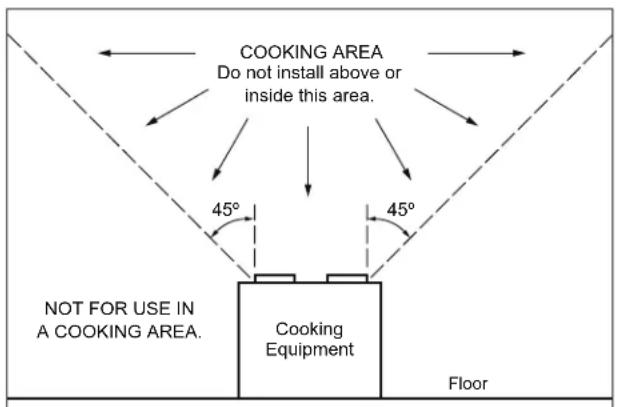
COOKING AREA Do not install above or inside this area. 45° 45° NOT FOR USE IN A COOKING AREA. Cooking Equipment Floor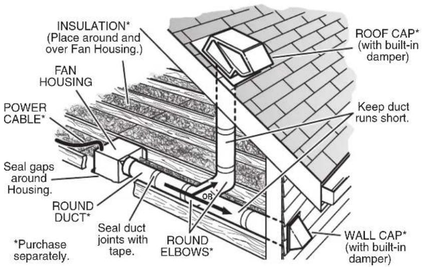
text_image
INSULATION* (Place around and over Fan Housing.) FAN HOUSING POWER CABLE* Seal gaps around Housing. ROUND DUCT* *Purchase separately. Insulation* (Place around and over Fan Housing.) ROOF CAP* (with built-in damper) Keep duct runs short. OB Seal duct joints with tape. ROUND ELBOWS* WALL CAP* (with built-in damper)Ducting has a strong effect on the air flow, noise and energy use of the fan. Use the shortest, straighest duct routing possible for best performance, and avoid installing the fan with smaller ducts than recommended. Insulation around the ducts can reduce energy loss and inhibit mold growth. Fans installed with existing ducts may not achieve their rated airflow.
8-inch round rigid metal duct is recommended for best performance.
TABLE OF CONTENTS
- WARRANTY .... 4
- TYPICAL INSTALLATION .... 5
2.1 MOUNTING (NEW FRAME CONSTRUCTION)....5
2.2 MOUNTING (EXISTING FRAME CONSTRUCTION)......5
- MOUNTING OPTIONS....6
- WIRING....7
- DUCTING 7-8
5.1 BLOWER DISCHARGE POSITIONS....8
5.2 HORIZONTAL BLOWER DISCHARGE....8
5.3 VERTICAL BLOWER DISCHARGE 8
- USE AND CARE 8
1. WARRANTY
Broan-NuTone warrants to the original consumer purchaser of its products that such products will be free from defects in materials or workmanship for a period of one year from the date of original purchase. THERE ARE NO OTHER WARRANTIES, EXPRESS OR IMPLIED, INCLUDING, BUT NOT LIMITED TO, IMPLIED WARRANTIES OF MERCHANTABILITY OR FITNESS FOR A PARTICULAR PURPOSE.
During this one-year period, Broan-NuTone will, at its option, repair or replace, without charge, any product or part which is found to be defective under normal use and service.
THIS WARRANTY DOES NOT EXTEND TO FLUORESCENT LAMP STARTERS AND TUBES. This warranty does not cover (a) normal maintenance and service or (b) any products or parts which have been subject to misuse, negligence, accident, improper maintenance or repair (other than by Broan-NuTone), faulty installation or installation contrary to recommended installation instructions.
The duration of an implied warranty is limited to the one-year period as specified for the express warranty. Some states do not allow limitation on how long an implied warranty lasts, so the above limitation may not apply to you.
BROAN-NUTONE'S OBLIGATION TO REPAIR OR REPLACE, AT BROAN-NUTONE'S OPTION, SHALL BE THE PURCHASER'S SOLE AND EXCLUSIVE REMEDY UNDER THIS WARRANTY. BROAN-NUTONE SHALL NOT BE LIABLE FOR INCIDENTAL, CONSEQUENTIAL OR SPECIAL DAMAGES ARISING OUT OF OR IN CONNECTION WITH PRODUCT USE OR PERFORMANCE. Some states do not allow the exclusion or limitation of incidental or consequential damages, so the above limitation may not apply to you.
This warranty gives you specific legal rights, and you may also have other rights, which vary from state to state. This warranty supersedes all prior warranties.
To qualify for warranty service, you must (a) notify Broan-NuTone at the address or phone number stated below (b) give the model number and part identification and (c) describe the nature of any defect in the product or part. At the time of requesting warranty service, you must present evidence of the original purchase date.
Broan-NuTone LLC, 926 West State Street, Hartford, WI 53027 1 800-558-1711 www.broan-nutone.com
Venmar Ventilation ULC, 550 Lemire Blvd., Drummondville, Québec Canada J2C 7W9 1 800-567-3855 www.broan-nutone.ca
2. TYPICAL INSTALLATION
WARNING
The wearing of safety glasses and gloves is recommended when installing, maintaining or cleaning the unit to reduce the risk of injury that could be caused by the presence of thin metal and/or moving parts.
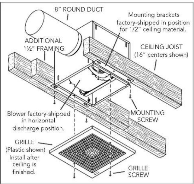
2.1 MOUNTING (NEW FRAME CONSTRUCTION)
text_image
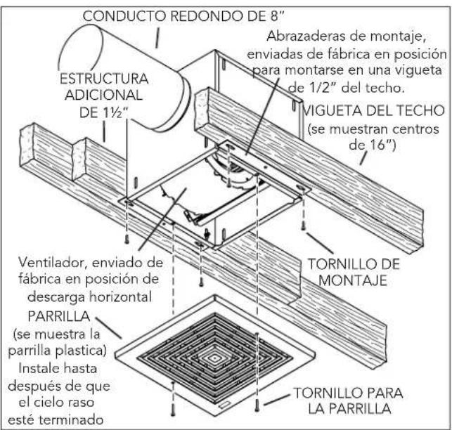
8" ROUND DUCT ADDITIONAL 1½" FRAMING Mounting brackets factory-shipped in position for 1/2" ceiling material. CEILING JOIST (16" centers shown) MOUNTING SCREW Blower factory-shipped in horizontal discharge position. GRILLE (Plastic shown) Install after ceiling is finished. GRILLE SCREWFactory-shipped unit installed in new construction.
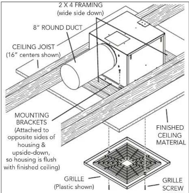
2.2 MOUNTING (EXISTING FRAME CONSTRUCTION)
text_image
2 X 4 FRAMING (wide side down) 8" ROUND DUCT CEILING JOIST (16" centers shown) MOUNTING BRACKETS (Attached to opposite sides of housing & upside-down, so housing is flush with finished ceiling) FINISHED CEILING MATERIAL GRILLE (Plastic shown) GRILLE SCREWFactory-shipped unit installed in existing construction.
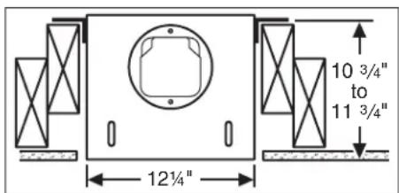
3. MOUNTING OPTIONS
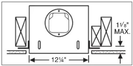
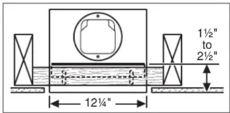
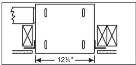
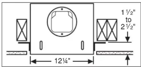
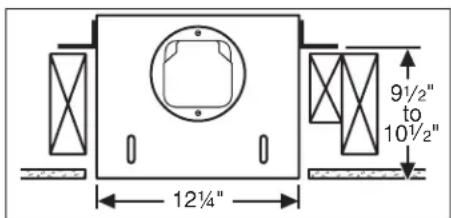
Use 1/4-20 hex. nuts to secure mounting brackets to housing. Loosen and re-tighten or remove and replace nuts as necessary for desired mounting bracket position.
text_image
12¼" 1½" MAX.Mounting brackets in factory-shipped position. (Outlet parallel to joists.) (New construction)
text_image
1½" to 2½" 12¼"Mounting brackets flipped over and mounted to outlet sides of housing. (Outlet parallel to joists.) (Existing construction)
text_image
12¼"Mounting brackets mounted to outlet sides of housing. (Outlet perpendicular to joists.) (New construction)
text_image
1½" to 2½" 12¼"Mounting brackets flipped over to give approx. 1" more clearance. (Outlet parallel to joists.) (New construction)
text_image
9½" to 10½" 12¼"Mounting brackets mounted to top of sides of housing. (Outlet parallel to joists.) (New or existing construction)
text_image
10 3/4" to 11 3/4" 12¼"Mounting brackets flipped over and mounted to top of sides of housing. (Outlet parallel to joists.) (New or existing construction)
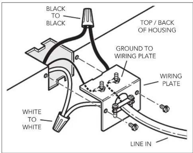
4. WIRING
WARNING
Electrical wiring must be done by a qualified person(s) in accordance with all applicable codes and standards, including fire-rated construction codes and standards.
text_image
BLACK TO BLACK TOP / BACK OF HOUSING GROUND TO WIRING PLATE WIRING PLATE WHITE TO WHITE LINE INVentilator can be wired from outside of housing. Use UL approved connectors to wire per local codes.
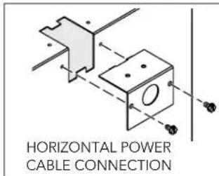
WIRING PLATE POSITION
text_image
HORIZONTAL POWER CABLE CONNECTION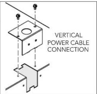
text_image
VERTICAL POWER CABLE CONNECTIONWiring plate mounts to side or top of housing.
5. DUCTING
CAUTION
Remove shipping tape from damper.
Remove the shipping tape from the damper flap and make sure that damper flap opens and closes freely inside the ductwork. Use duct tape to make ductwork connections secure and air-tight.
CAUTION
Remove shipping ring from blower inlet.
Remove the shipping ring from the blower inlet before operating the ventilator.
5.1 BLOWER DISCHARGE POSITIONS
text_image
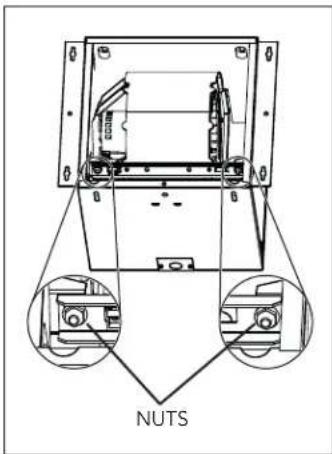
NUTSTo remove blower: unplug blower and remove 2 blower retaining nuts
text_image
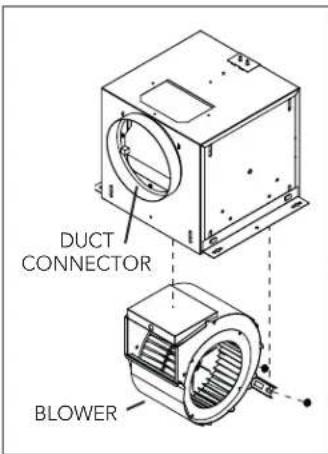
DUCT CONNECTOR BLOWERBlower and duct connector in horizontal discharge position. (Factory shipped)
text_image
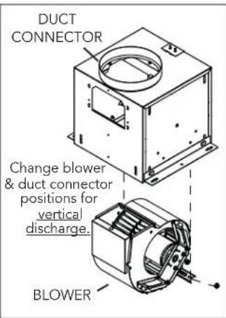
DUCT CONNECTOR Change blower & duct connector positions for vertical discharge. BLOWERBlower and duct connector in vertical discharge position.
5.2 HORIZONTAL BLOWER DISCHARGE
text_image
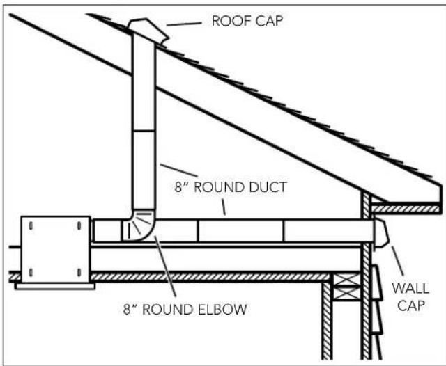
ROOF CAP 8" ROUND DUCT 8" ROUND ELBOW WALL CAPTwo ways to connect ductwork to a factory-shipped unit.
5.3 VERTICAL BLOWER DISCHARGE
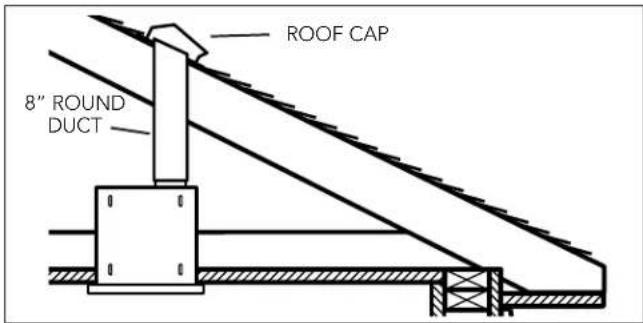
text_image
ROOF CAP 8" ROUND DUCTTypical ductwork connection to a ventilator converted to vertical discharge.
6. USE AND CARE
Ventilator is designed for continuous operation. If desired, it may be controlled using an on/off switch or a solid-state, variable speed control. Follow wiring instructions packed with control, and adhere to all local and state codes, and the National Electrical Code.
! WARNING
To reduce the risk of electric shock, disconnect from power supply before servicing.
To clean grille: Use vacuum soft brush attachment or remove grille and clean with a soft cloth and mild soap or detergent. Dry grille thoroughly before reinstalling.
To clean blower assembly: Remove grille, unplug blower from housing, remove blower mounting nuts, and carefully remove blower from housing. Vacuum blower and interior of unit with the dusting brush attachment.
Motor is permanently lubricated. Do not oil or disassemble motor.
If the product is making excessive or unusual noises, replace the blower assembly.
BROAN®
GUIDE D'INSTALLATION ET D'UTILISATION
VENTILATEUR DE TYPE COMMERCIAL LÉGER CERTIFIÉS ENERGY STAR®
MONTAGE AU PLAFOND OU AU MUR
MODÈLES L100E - L150E - L200E - L250E - L300E
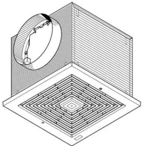
natural_image
Isometric architectural diagram showing a circular structure with a rectangular base and concentric square patterns (no text or symbols)

text_image
CAN BE USED TO COMPLY WITH IECC-C 2021
text_image
CAN BE USED TO COMPLY WITH IMC 2021
text_image
Energy ENERGY STAR

text_image
® 2100 HVI CERTIFIEDBroan-NuTone LLC, 926 West State Street, Hartford, WI 53027 1 800 558-1711 www.broan-nutone.com
Venmar Ventilation ULC, 550 boul. Lemire, Drummondville, Québec Canada J2C 7W9 1 800 567-3855 www.broan-nutone.ca
2. INSTALLATION TYPE
AVERTISSEMENT
natural_image
Isometric technical diagram of a mechanical or architectural component with concentric square patterns and a circular inset showing a cylindrical feature (no text or symbols)


text_image
CAN BE USED TO COMPLY WITH IMC 2021
text_image
Energy ENERGY STAR

text_image
® 2100 HVI CERTIFIEDBroan-NuTone LLC, 926 West State Street, Hartford, WI 53027 1 800-558-1711 www.broan-nutone.com
Venmar Ventilation ULC, 550 boul. Lemire, Drummondville, Québec Canada J2C 7W9 1 800-567-3855 www.broan-nutone.ca
2.1 MONTAJE (ESTRUCTURA NUEVA)