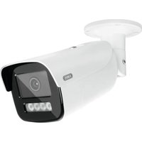
IPCB44510B - Surveillance Camera ABUS - Free user manual and instructions
Find the device manual for free IPCB44510B ABUS in PDF.

User questions about IPCB44510B ABUS
0 question about this device. Answer the ones you know or ask your own.
Ask a new question about this device
Download the instructions for your Surveillance Camera in PDF format for free! Find your manual IPCB44510B - ABUS and take your electronic device back in hand. On this page are published all the documents necessary for the use of your device. IPCB44510B by ABUS.
USER MANUAL IPCB44510B ABUS
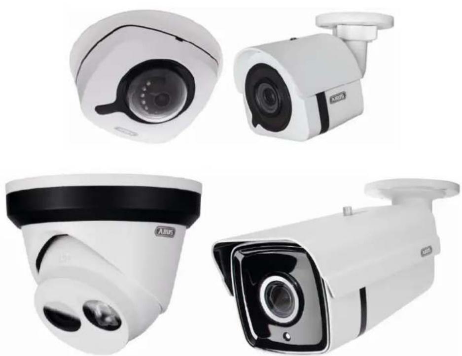
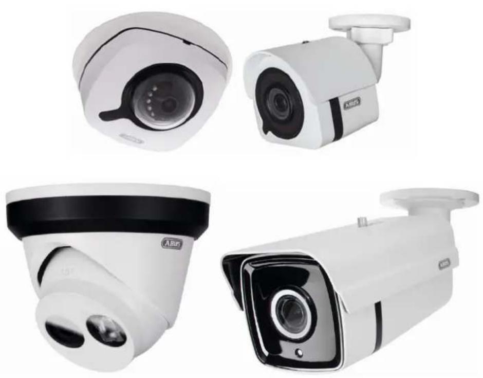
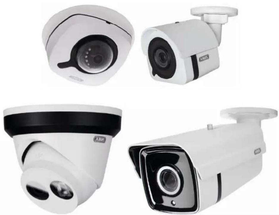
IPCB42510A / IPCB42510B / IPCB42510C / IPCB42515A /
IPCB44510A / IPCB44510B / IPCB44510C / IPCB62510A /
IPCB62510B / IPCB62510C / IPCB64510A / IPCB64510B /
IPCB64510C / IPCB68510A / IPCB68510B / IPCB68510C /
IPCB62515A / IPCB64515B / IPCB68515A / IPCB72515A /
IPCB74515B / IPCB78515A / IPCB74615B / IPCB78615A
TVIP44510 / TVIP48510 / TVIP64510 / TVIP68510
D Bedienungsanleitung Software
UK User manual software
FR Manuel utilisateur logiciel
NL Gebruikershandleiding software
DK Brugerhåndbog software
| D | Diese Bedienungsanleitung enthält wichtige Hinweise zur Inbetriebnahme und Handhabung.Achten Sie hierauf, auch wenn Sie dieses Produkt an Dritte weitergeben.Heben Sie deshalb diese Bedienungsanleitung zum Nachlesen auf!Eine Auflistung der Inhalte finden Sie im Inhaltsverzeichnis mit Angabe der entsprechenden Seitenzahlen auf Seite 8. | DK | Denne manual hører sammen med dette produkt. Den indeholder vigtig information som skal bruges under opsætning og efterfølgende ved service. Dette skal huskes også når produkter gives videre til anden part. Læs derfor denne manual grundigt igennem også for fremtiden.Indholdet kan ses med sideanvisninger kan findes i indekset på side 229. |
| GB | These user manual contains important information for installation and operation. This should be also noted when this product is passed on to a third party. Therefore look after these operating instructions for future reference!A list of contents with the corresponding page number can be found in the index on page 64. | ||
| F | Ce mode d'emploi appartient à de produit. Il contient des recommandations en ce qui concerne sa mise en service et sa manutention. Veuillez en tenir compte et ceci également lorsque vous remettez le produit à des tiers. Conservez ce mode d'emploi afin de pouvoir vous documenter en temps utile!Vous trouverez le récapitulatif des indications du contenu á la table des matières avec mention de la page correspondante á la page 118. | ||
| NL | Deze gebruiksaanwijzing hoort bij dit product. Er staan belagrijke aanwijzingen in betreffende de ingebruikname en gebruik, ook als u dit product doorgeeft aan derden. Bewaar deze handleiding zorgvuldig, zodat u deze later nog eens kunt nalezen!U vindt een opsomming van de inhoud in de inhoudsopgave met aanduiding van de paginanummers op pagina 174. | ||
IPCB42510A / IPCB42510B / IPCB42510C / IPCB42515A / IPCB44510A / IPCB44510B / IPCB44510C / IPCB62510A / IPCB62510B / IPCB62510C / IPCB64510A / IPCB64510B / IPCB64510C / IPCB68510A / IPCB68510B / IPCB68510C / IPCB62515A / IPCB64515B / IPCB68515A / IPCB72515A / IPCB74515B / IPCB78515A / IPCB74615B / IPCB78615A / TVIP44510 / TVIP48510 / TVIP64510 / TVIP68510
text_image
http://192.168.0.100/doc/page/config.asp ABUS Network Camera ? Logged in as installer7.3 Dashboard
IPye Standard Gateway
三
MAC-Adresse
8c11:cb:0b:4a:be
MTU
1500
IPCB42515A-8C11CB0B4ABE
Manuell
Port Type
Externer Port
Externe IP-Adresse
Interner Port
Status
HTTP
80
0.0.0.0
80
Ungültig
RTSP
554
0.0.0.0
554
Ungültig
Server Port
8000
0.0.0.0
8000
Ungültig
7.4.3.5 SNMP
SNMP (Simple Network Management Protocol)
Trap-Community: TRAP-Community String
Private-Key-Algorithmus
Private-Key-Kennwort
Private Key Algorithmus
Private-Key-Kennwort
no auth, no pclv
MD5 SHA
■■■■■
DES AES
......
SNMP Sonst. Einst.
SNMP-Port
161
7.4.3.6 FTP
7.4.3.7 ABUS Link Station
C=DE, ST=BY, L=AF, OU=abusIPcamera, H/IP=192.168.1.64
tösten
Thema: C-DE, ST-BY, L-AF, OU-abusIPcamera, H/IP=192.168.1.64, EM=de Herausgeber: C-DE, ST-BY, L-AF, OU-abusIPcamera, H/IP=192.168.1.64, EM=de Gültigkelt: 2018-10-18 11:36×42
7.4.3.9 QoS
DSCP - Differentiated Service CodePoint
text_image
Name Zeitplane
1 24h Mon Tues Wed Thu Fri Sat Sun Hinsartgen Beatbetten Losches7.10 Detektoren
IPCB42510A / IPCB42510B / IPCB42510C / IPCB42515A /
IPCB44510A / IPCB44510B / IPCB44510C / IPCB62510A /
IPCB62510B / IPCB62510C / IPCB64510A / IPCB64510B /
IPCB64510C / IPCB68510A / IPCB68510B / IPCB68510C /
IPCB62515A / IPCB64515B / IPCB68515A / IPCB72515A /
IPCB74515B / IPCB78515A / IPCB74615B / IPCB78615A
User guide
Software
Version 04/2020
CE
English translation of the original German instruction manual. Retain for future reference.

Introduction
Dear Customer,
Thank you for purchasing this product.
IPCB42510A
The device complies with the requirements of the following EU directives: EMC Directive 2014/30/EU and the RoHS Directive 2011/65/EU.
IPCB42510B
The device complies with the requirements of the following EU directives: EMC Directive 2014/30/EU and the RoHS Directive 2011/65/EU.
IPCB42510C
The device complies with the requirements of the following EU directives: EMC Directive 2014/30/EU and the RoHS Directive 2011/65/EU.
IPCB42515A
ABUS Security-Center hereby declares that the device IPCB42551 complies with Radio Equipment Directive (RED) 2014/53/EU. Additionally, this device complies with the requirements of the following EU directives: EMC Directive 2014/30/EU and the RoHS Directive 2011/65/EU. The full EU Declaration of Conformity text can be found at: www.abus.com/IPCB42515A
IPCB44510A
The device complies with the requirements of the following EU directives: EMC Directive 2014/30/EU and the RoHS Directive 2011/65/EU.
IPCB44510B
The device complies with the requirements of the following EU directives: EMC Directive 2014/30/EU and the RoHS Directive 2011/65/EU.
IPCB44510C
The device complies with the requirements of the following EU directives: EMC Directive 2014/30/EU and the RoHS Directive 2011/65/EU.
IPCB62510A
The device complies with the requirements of the following EU directives: EMC Directive 2014/30/EU and the RoHS Directive 2011/65/EU.
IPCB62510B
The device complies with the requirements of the following EU directives: EMC Directive 2014/30/EU and the RoHS Directive 2011/65/EU.
IPCB62510C
The device complies with the requirements of the following EU directives: EMC Directive 2014/30/EU and the RoHS Directive 2011/65/EU.
IPCB64510A
The device complies with the requirements of the following EU directives: EMC Directive 2014/30/EU and the RoHS Directive 2011/65/EU.
IPCB64510B
The device complies with the requirements of the following EU directives: EMC Directive 2014/30/EU and the RoHS Directive 2011/65/EU.
IPCB64510C
The device complies with the requirements of the following EU directives: EMC Directive 2014/30/EU and the RoHS Directive 2011/65/EU.
IPCB68510A
The device complies with the requirements of the following EU directives: EMC Directive 2014/30/EU and the RoHS Directive 2011/65/EU.
IPCB68510B
The device complies with the requirements of the following EU directives: EMC Directive 2014/30/EU and the RoHS Directive 2011/65/EU.
IPCB68510C
The device complies with the requirements of the following EU directives: EMC Directive 2014/30/EU and the RoHS Directive 2011/65/EU.
IPCB62515A
The device complies with the requirements of the following EU directives: EMC Directive 2014/30/EU and the RoHS Directive 2011/65/EU.
IPCB64515B
The device complies with the requirements of the following EU directives: EMC Directive 2014/30/EU and the RoHS Directive 2011/65/EU.
IPCB68515A
The device complies with the requirements of the following EU directives: EMC Directive 2014/30/EU and the RoHS Directive 2011/65/EU.
IPCB72515A
The device complies with the requirements of the following EU directives: EMC Directive 2014/30/EU and the RoHS Directive 2011/65/EU.
IPCB74515B
The device complies with the requirements of the following EU directives: EMC Directive 2014/30/EU and the RoHS Directive 2011/65/EU.
IPCB78515A
The device complies with the requirements of the following EU directives: EMC Directive 2014/30/EU and the RoHS Directive 2011/65/EU.
IPCB74615B
The device complies with the requirements of the following EU directives: EMC Directive 2014/30/EU and the RoHS Directive 2011/65/EU.
IPCB78615A
The device complies with the requirements of the following EU directives: EMC Directive 2014/30/EU and the RoHS Directive 2011/65/EU.
TVIP44510
The device complies with the requirements of the following EU directives: EMC Directive 2014/30/EU and the RoHS Directive 2011/65/EU.
TVIP48510
The device complies with the requirements of the following EU directives: EMC Directive 2014/30/EU and the RoHS Directive 2011/65/EU.
TVIP64510
The device complies with the requirements of the following EU directives: EMC Directive 2014/30/EU and the RoHS Directive 2011/65/EU.
TVIP68510
The device complies with the requirements of the following EU directives: EMC Directive 2014/30/EU and the RoHS Directive 2011/65/EU.
To ensure this remains the case, and to guarantee safe operation, you the user must observe the instructions in this user guide.
Read the entire user guide carefully before starting operation of the product, and pay attention to all operating instructions and safety information.
All company names and product descriptions are trademarks of the corresponding owner. All rights reserved.
If you have any questions, please contact your specialist installation contractor or specialist dealer.

Disclaimer
This user guide has been produced with the greatest of care. Should you discover any missing information or inaccuracies, please let us know about them.
ABUS Security-Center GmbH & Co. KG does not accept any liability for technical and typographical errors, and reserves the right to make changes to the product and user manuals at any time and without prior warning.
ABUS Security-Center GmbH is not liable or responsible for any direct or indirect damage resulting from the installation, performance and use of this product. No guarantee is made for the contents of this document.
Important safety information
All guarantee claims are invalid in the event of damage caused by non-compliance with this user manual. We cannot be held liable for resulting damage.

We cannot be held liable for material or personal damage caused by improper operation or non-compliance with the safety information. All guarantee claims are void in such cases.
Dear Customer,
The following safety information and hazard notes are not only intended to protect your health but also to protect the device from damage. Please read the following points carefully:
- There are no components inside the product that require maintenance by the operator. Opening or dismantling the product invalidates the CE certification and guarantee claims/warranty.
- The product may be damaged if it is dropped, even from a low height.
Avoid the following adverse conditions during operation:
- Moisture or excess humidity
• Extreme heat or cold - Direct sunlight
- Dust or flammable gases, vapours or solvents
- Strong vibrations
• Strong magnetic fields (e.g. next to machines or loudspeakers) - The camera must not be installed on unstable surfaces.
General safety information:
- Do not leave packaging material lying around. Plastic bags, sheeting, polystyrene packaging, etc. can pose a danger to children if played with.
- The video surveillance camera contains small parts which could be swallowed and must be kept out of the reach of children for safety reasons.
- Do not insert any objects into the device through the openings.
- Only use replacement devices and accessories that are approved by the manufacturer. Do not connect any non-compatible products.
- Please pay attention to the safety information and user manuals for the other connected devices.
- Check the device for damage before putting it into operation. Do not put the device into operation if you identify any damage.
- Adhere to the normal voltage limits specified in the technical data. Higher voltages could destroy the device and pose a health risk (electric shock).
When installing the device in an existing video surveillance system, ensure that all devices have been disconnected from the mains power circuit and low-voltage circuit.

If in doubt, have a specialist technician carry out assembly, installation and connection of the device. Improper or unprofessional work on the power supply system or domestic installation puts both you and other persons at risk.
Connect the installations so that the mains power circuit and low-voltage circuit always run separately from each other. They should not be connected at any point or become connected as a result of a malfunction.
Contents
- INTENDED USE 66
- EXPLANATION OF SYMBOLS....66
- FEATURES AND FUNCTIONS....67
- INITIAL START-UP 68
4.1 U SING THE ABUS IP INSTALLER FOR CAMERA SEARCH 68
4.2 A CCESSING THE NETWORK CAMERA VIA A WEB BROWSER....69
4.3 | NITIAL PASSWORD ASSIGNMENT 69
4.4 G GENERAL INSTRUCTIONS FOR USING THE SETTINGS PAGES 70
4.5 I INSTALLING A VIDEO PLUGIN 70
4.6 H OME PAGE (LOGIN PAGE)....71
4.7 U SER ACCOUNTS AND PASSWORDS 72
4.8 C ONNECTING THE CAMERA TO ABUS NVR 73
4.9 C ONNECTING THE CAMERA TO IPCAM PLUS 73
-
USER MENU "USER" 74
-
VIEW AND CONFIGURATION MENU USER "MASTER"...... 75
6.1 L OCAL CONFIGURATION....76
6.2 D ISPLAYING/DOWNLOADING A RECORDING FROM THE INTERNAL MEMORY 77
- VIEW AND CONFIGURATION MENUS USER "INSTALLER" 79
7.1 L IVE VIEW 79
7.2 Q QUICK HELP 79
7.3 D ASHBOARD 80
7.4 S YSTEM....81
7.4.1 Date & time 81
7.4.2 Daylight saving time (DST) 82
7.4.3 Network 82
7.4.4 Licence information.... 91
7.4.5 Update & reset 91
7.4.6 Miscellaneous 92
7.4.7 Contacts 93
7.4.8 Authentication 93
7.4.9 Security 93
7.5 V IDEO 94
7.5.1 Video stream....94
7.5.2 Image 95
7.5.3 OSD 96
7.5.4 Privacy mask....97
7.6 A AUDIO 98
7.7 S TORAGE 98
7.7.1 Record schedule 98
7.7.2 Single frame recording....99
7.7.3 Storage management 101
7.7.4 Network drive 101
7.8 L OCAL SETTINGS....101
7.9 S CCHEDULES....103
7.10 D ETECTORS.... 103
7.10.1 Motion detection.... 103
7.10.2 Cover detection.... 104
7.10.3 Alarm input 104
7.10.4 Scene change detection.... 105
7.10.5 Intrusion detection.... 105
7.10.6 Tripwire detection.... 106
7.11 O UTPUTS.... 107
7.12 U SERS.... 107
7.12.1 Managing users.... 107
7.12.2 Online users.... 108
7.13 E MAIL 108
7.14 E VENT MANAGER.... 110
8. MAINTENANCE AND CLEANING.... 111
8.1 FUNCTION TEST 111
8.2 CLEANING 111
9. DISPOSAL....111
1. Intended use
This camera is used for indoor and outdoor video surveillance (depending on the model) in conjunction with a recording device or appropriate display unit (e.g. PC).

Use of this product for any other purpose than that described may lead to damage to the product and other hazards. All other uses are not as intended and will result in the invalidation of the product guarantee and warranty. No liability can be accepted as a result. This also applies to any alterations or modifications made to the product.
Read the user guide carefully and in full before putting the product into operation.
The user guide contains important information on installation and operation.
2. Explanation of symbols

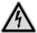
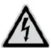
The triangular high voltage symbol is used to warn of the risk of injury or health hazards (e.g. caused by electric shock).

The triangular warning symbol indicates important notes in this user guide which must be observed.

This symbol indicates special tips and notes on the operation of the unit.

This user manual describes the software functions in the camera browser interface. For information about how to install the hardware for the respective camera, please read the quick start manual or the hardware installation manual, if you have it.
You can download a PDF version of the user manuals in your language at www.abus.com via the product search.
3. Features and functions
| Design Resolution | Lens focal | length | IR Wi-Fi | ||
| IPCB42510A | Mini dome 2 MPx 2.8 mm | √ | - | ||
| IPCB42510B | Mini dome | 2 MPx | 4.0 mm | √ | - |
| IPCB42510C | Mini dome | 2 MPx | 6.0 mm | √ - | |
| IPCB42515A | Mini dome | 2 MPx | 2.8 mm | √ | √ |
| IPCB44510A | Mini dome 4 MPx 2.8 mm | √ - | |||
| IPCB44510B | Mini dome | 4 MPx | 4.0 mm | √ - | |
| IPCB44510C | Mini dome | 4 MPx | 6.0 mm | √ - | |
| IPCB62510A | Mini tube 2 MPx 2.8 mm | √ - | |||
| IPCB62510B | Mini tube | 2 MPx | 4.0 mm | √ - | |
| IPCB62510C | Mini tube | 2 MPx | 6.0 mm | √ - | |
| IPCB64510A | Mini tube | 4 MPx | 2.8 mm | √ - | |
| IPCB64510B | Mini tube | 4 MPx | 4.0 mm | √ - | |
| IPCB64510C | Mini tube | 4 MPx | 6.0 mm | √ - | |
| IPCB68510A | Mini tube 8 MPx 2.8 mm | √ - | |||
| IPCB68510B | Mini tube | 8 MPx | 4.0 mm | √ - | |
| IPCB68510C | Mini tube | 8 MPx | 6.0 mm | √ - | |
| IPCB62515A | Fix Tube 2 MPx 2.8 mm | √ | - | ||
| IPCB64515B | Fix Tube 4 MPx 4 mm | √ - | |||
| IPCB68515A | Fix Tube 8 MPx 2.8 mm | √ - | |||
| IPCB72515A | Fix Dome | 2 MPx | 2.8 mm | √ - | |
| IPCB74515B | Fix Dome | 4 MPx | 4 mm | √ - | |
| IPCB78515A | Fix Dome | 8 MPx | 2.8 mm | √ - | |
| IPCB74615B | Fix Dome | 4 MPx | 4 mm | √ - | |
| IPCB78615A | Fix Dome | 8 MPx | 2.8 mm | √ - | |
| TVIP44510 | Fix Dome | 4 MPx | 2.8 mm | √ - | |
| TVIP48510 | Fix Dome | 8 MPx | 2.8 mm | √ - | |
| TVIP64510 | Fix Tube 4 MPx 2.8 mm | √ - | |||
| TVIP68510 | Fix Tube 8 MPx 2.8 mm | √ - | |||

The effective IR range will depend on the installation location. If there are surfaces that absorb light or no objects that reflect IR light in the field of view, the IR range will be reduced and/or the video image will be too dark. Reflective objects in the immediate vicinity of the camera (e.g. roof gutter or wall) may also result in the reflection of IR light, which can disturb the image.
4. Initial start-up
4.1 Using the ABUS IP Installer for camera search
Install and start up the ABUS IP Installer (which is available for each respective product from the ABUS website www.abus.com).
The IP camera should now appear in the selection list without the relevant IP address for the target network, where appropriate.
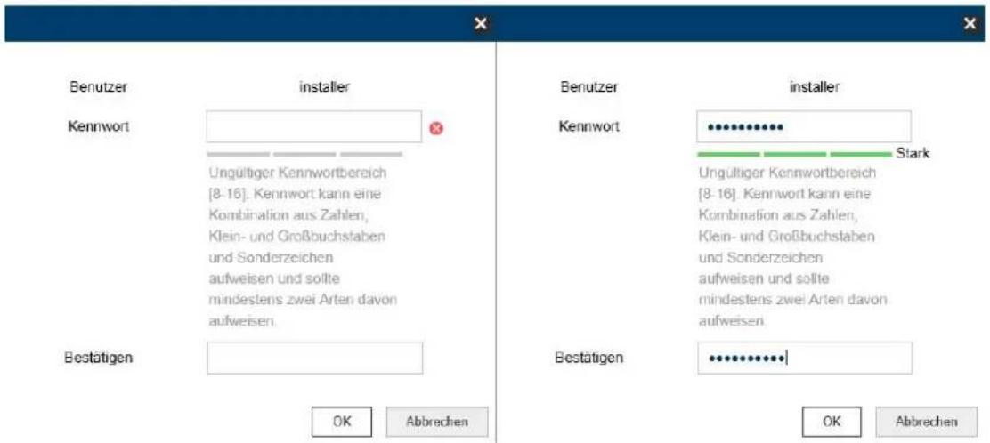
The camera must first be enabled, i.e. a correspondingly secure password must be assigned for the main user "installer". A secure password must meet the following minimum requirements:
- 8–16 characters
- Valid characters: numbers, lower-case letters, capital letters, special characters ( ! \$ % & / () = ? + - )
- You must use at least two different types of character
The password can also be initially assigned via the web browser.
The IP settings for the camera can be changed using the IP installer.
The language preference for the camera can also be changed using the ABUS IP installer.

Please be aware, that the language preference for the camera homepage is set automatically depending on the operating system language preference. If this language is not available in the camera, the homepage will be shown in English.
Using the "Browser" button, a previously selected camera can be opened directly in the internet browser (the default browser for Windows will be used).
4.2 Accessing the network camera via a web browser
Enter the camera IP address into the address bar in the browser (if a different HTTP Port is used in Internet Explorer you must also enter "http://" before the IP address.)

text_image
http://192.168.0.100/doc/page/config.asp ABUS Network Camera4.3 Initial password assignment
For IT security reasons, use of a secure password with the appropriate usage of lower-case letters, capital letters, numbers and special characters is recommended.
Passwords are not factory set and must be assigned when the camera is used for the first time. This can be done via the ABUS IP installer ('Enable' button), or via the website.
A secure password must meet the following minimum requirements:
- 8–16 characters
- Valid characters: numbers, lower-case letters, capital letters, special characters ( ! \$ % & / () = ? + - )
- You must use at least two different types of character
4.4 General instructions for using the settings pages
| Functional element Description | |
 | Save settings that have been made on the page.Please note that the new settings will only apply after the save button has been pressed. |
 | Function activated |
 | Function deactivated |
24-Stunden  | List selection |
 | Input field |
 | Slide control |
4.5 Installing a video plugin
Internet Explorer
A plugin called ActiveX is used for displaying videos in Internet Explorer. This plugin must be installed in the browser. You will be asked to confirm the installation directly after entering your user name and password.
 | If the ActiveX Plugin installation is blocked by Internet Explorer, you will need to reduce your security settings to install/initialise ActiveX. |
Mozilla Firefox/Google Chrome/Microsoft Edge
A compatible format is used for displaying videos in these browsers. For resource reasons, it is only possible to display the second video stream (max. 640x360 pixels). In addition, local playback of video data from the internal microSD card/NAS is not possible. Image parameters, detectors and private zones can be configured.
It is not possible to update the camera's firmware in these browsers.
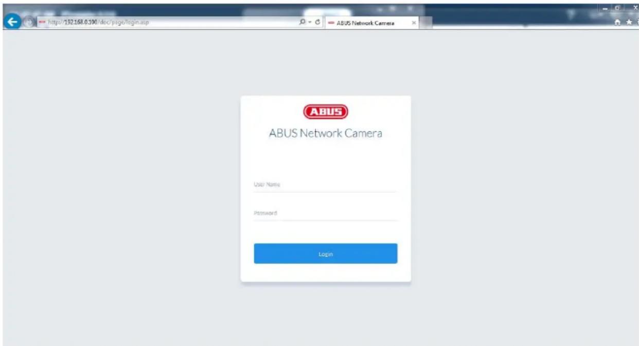
4.6 Home page (login page)
After entering the IP address in the browser's address bar and opening up the page, the home page will appear in the language set in the Internet Explorer options (Windows setting).
Each respective user account (installer, master or user) can set their language individually. For example, the settings pages can be set to English for the "installer" account and German for the "master" account.
The following languages are supported: German, English, French, Dutch, Danish. If a language is not supported, the website will be displayed in English.
text_image
http://192.168.0.100/doc/page/login.asp ABUS Network Camera ABUS ABUS Network Camera User Name Password Login4.7 User accounts and passwords
Overview of the types of user with the user name descriptions, the default passwords and corresponding privileges:
| User type User name | Default password Privileges | ||
| INSTALLER(for access via web browser, mobile app or recording device) | Installer | <assigned and modified by installer> | Video display on web browserInstant imageLocal video recording on PCControl microphone/Speaker (optional)Full screen mode in browserZoom/Focus setting (if available)System overviewImage settingsVideo streaming quality settingsDay/night switchingPrivacy maskingIP address settingsNetwork protocol settingsSetting for connection portsDDNS settingsHTTPS settingsSMTP settingsDisplayed textDate/TimeExport/Import/RestoreFirmware update/RestartLog fileMotion detection settingsAlarm management (email/switch output)Audio parameters (optional)Playback of recordings from the internal memory (only IE11) |
| MASTERand modified by installer> | <assigned and modified by installer>Video display on web browserInstant imageLocal video recording on PCControl microphone/Speaker (optional)Full screen mode in browserPlayback of recordings from the internal memory (only IE11) | ||
| USERmodified by installer> | <assigned and modified by installer>Video display on web browserInstant imageLocal video recording on PCControl microphone/Speaker (optional)Full screen mode in browser | ||
4.8 Connecting the camera to ABUS NVR
The following information is required to connect the camera to ABUS NVR:
• IP address/domain name
• Server Port (Standard 8000)
- User name: installer
- Password:
4.9 Connecting the camera to IPCam Plus
The following information is required to link up the camera with IPCam:
• IP address/domain name
- http port (default 80)
- rtsp port (default 554)
- User name: installer
- Password:
5. User menu "user"
| Button/display on screen | Function | |
 | Instant image functionThis function saves an instant image from the current video stream in JPEG format. The picture is stored in the following folder:(Save location, see local configuration) | |
 | Video functionThis function saves a video from the current video stream in AVI format.The video is stored in the following folder:(Save location, see local configuration) | |
 | Muting the microphone (if available)This button can be used to deactivate the microphone in the camera or the microphone in the optional audio input. | |
 | Muting the speaker (if available)This button can be used to deactivate the speaker in the optional audio output. | |
 | Full screen modeSwitching the video picture on the monitor to full screen mode (you can also do this by double clicking within the video frame). You can exit full screen mode by double clicking within the video frame again or pressing the ESC button. | |
 | Digital zoom: press this button and draw a rectangle in the video area by holding down the left mouse button. To deactivate the digital zoom, press the left mouse button again. | |
 | Log out as user. Afterwards the login page is displayed again. | |
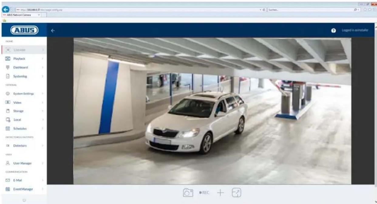
6. View and configuration menu user "master"
natural_image
Exterior view of a white car parked inside a modern parking garage (no signage)| Button/display on screen | Function |
 | Instant image functionThis function saves an instant image from the current video stream in JPEG format (see Local Configuration for save location). |
 | Video functionThis function saves a video from the current video stream in AVI format (see Local Configuration for save location). |
 | Muting the microphone (if available)This button can be used to deactivate the microphone in the camera or the microphone in the optional audio input. |
 | Muting the speaker (if available)This button can be used to deactivate the speaker in the optional audio output. |
 | Full screen modeSwitching the video picture on the monitor to full screen mode (you can also do this by double clicking within the video frame). You can exit full screen mode by double clicking within the video frame again or pressing the ESC button. |
 | Digital zoom: press this button and draw a rectangle in the video area by holding down the left mouse button. To deactivate the digital zoom, press the left mouse button again. |
| Log out as user. Afterwards the login page is displayed again. |
6.1 Local configuration
Local
Live View Parameters
Protocol
Live View Performance
Live Indicator
Display POS Information
Image Format
TCP
○ UDP
MULTICAST
○ HTTP
○ Shortest Delay
Balanced
Fluent
● Enable
○ Disable
● Enable
○ Disable
JPEG
BMP
Record File Settings
Record File Size
Save record files to
Save downloaded files to
256M
S12M
○1G
C:\Users\Agentur\Web\RecordFiles
Browse
Open
C:\Users\Agentur\Web\DownloadFiles
Browse
Open
Picture and Clip Settings
Save snapshots in live view to
Save snapshots when playback to
Save clips to
C:\Users\Agentur\Web\CaptureFiles
C:\Users\Agentur\Web\PlaybackPlcs
C:\Users\Agenturi\Web\PlaybackFiles
Bronde
Open
Browse
Open
Brook
Open
Protocol: Setting the transmission protocol (default: TCP)
Live view performance: Select the priority for display in the browser here (priority on image stream or image quality).
Live indicator: Display of all event animations in the live image (e.g. frame for motion detection). These animations are also recorded to the recording device.
Image format: Select the encoding format for saving single frames using the browser live interface.
Record file size: Select the size of video sequences for saving videos
using the browser live interface.
Save record files to: Select the path for video recording.
Save downloaded files to: Select the path for video files downloaded from the SD card.
Save live snapshots to: Select the encoding format for saving images using the browser live interface.
Snapshots during playback: Select the path for saving images during playback.
Save clips to: Select the path for saving video clips during playback.
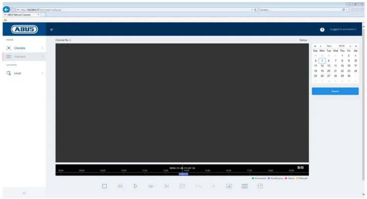
6.2 Displaying/downloading a recording from the internal memory
text_image
http://18.160.8.37 (www.norfs verification) ABUS Network Camera AOS Overview Playback Local Channel No. 1 Status: New 2018 Sun Mon Tue Wed Thu Fri Sat 4 5 6 7 8 9 10 11 12 13 14 15 16 17 18 19 20 21 22 23 24 25 26 27 28 29 30 Search Command Continuous Alarm Manual| Symbol Explanation | ||
 | Selection of the date when searching for a recording. If data are found on the SD card, they are displayed in the playback bar by record type.First select a date and then click "SEARCH". | |
 | Stop playback | |
 | Slow playback (forwards) | |
 | Fast playback (forwards) | |
 | Frame forwards | |
 | Playback volume (if recording contains audio data) | |
 | Enable digital zoom. Then hold down the left mouse button to draw a rectangle in the video area. The digital zoom is applied to this area. Pressing this button a second time closes the digital zoom mode. | |
 | Save single frame (save location, see local configuration) | ||
 | Start/stop the video cutting function. The cut video is saved after you press stop (save location, see local configuration). | ||
 | Opens a dialogue for downloading recorded video files from the SD card. | ||
 | Opens a dialogue for downloading recorded image files from the SD card. | ||
 | Playback bar with time and date display (display depends on temporal zoom factor). The recorded data are displayed colour-coded by record type in the playback bar. | ||
 | Setting the temporal zoom factor | ||
7. View and configuration menus user "installer"
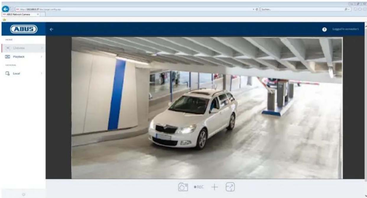
7.1 Live view
The live view display for the installer user is similar to that of the master user. However, the installer user has extended options for settings such as the set up wizard or extended configuration.
text_image
https://192168.8.37 direct page coming up ABUS Network Camera LABGED IN AS/INSTALLER HOME Listener Playback Dashboard Systemlog GENERAL System Settings Video Storage Local Schedules DETAILS & OUTPUTS Detectors User Manager COMMUNICATION E-Mail EventManager(Example image: IPCB42515A)
7.2 Quick help
Pressing this button in the top right corner displays information on the individual settings on many of the settings pages.

text_image
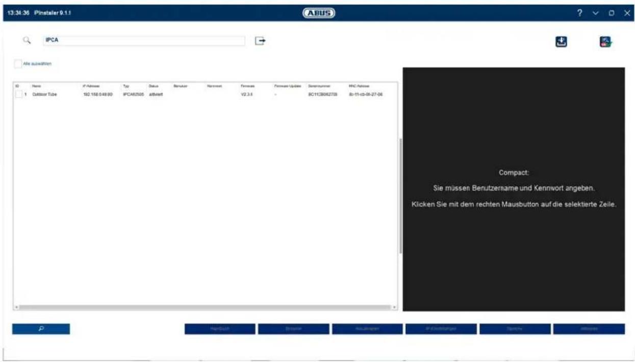
http://192.168.0.100/doc/page/config.asp ABUS Network Camera ? Logged in as Installer7.3 Dashboard
The dashboard displays general information about the camera, e.g. installed firmware version or serial number of the camera.

text_image
ABUS Network Camera Legend in as Installer ABUS Network Camera Model PCB68510 Serial No PCB6851009300704AAWRB65079325 Firmware Version V5.5.52build 1R0912 Encoding Version V7.3 bywd 1R0022 Web Version V4.0.51bywd 1R0911 Plug Version V3.0.6/202 Number of Channels 1 Number of HDDs 1 Number of Alarm Input 2 Number of Alarm Output 3 Fireware Version-Property C4-010 SYSTEM STATUS-OK PHUANO 97% TRAFFC EIRIUSIn the area to the upper right, the general status of the system is represented by a symbol.
 | System is running correctlyAll parameters such as system temperature and processor usage are fine.All functions in use are working correctly. | |
 | System is faultyErrors have occurred in the system. But these are not critical to the basic functionality of the camera. However, they could cause limitations or malfunctions within certain functions. The system may need to be tested by the installer. | |
 | System condition is criticalCertain parameters such as system temperature or processor usage are critical for the system. The system must be tested by the installer immediately. |
Type: Camera item number
Serial No.: Camera serial number
Firmware version: Display of the firmware version currently installed
Coding version: Version number of the video encoder
Web version: Version number of the website
Plugin version: Version of the video plugin on the camera
Number of Channels: Typically, only 1 channel is shown for a camera. A number of camera channels may be available for IP encoders.
Number of HDDs: Display of the number of installed storage media (e.g. microSD card)
Number of Alarm Input: Number of switching inputs on the camera
Number of alarm outputs: Number of switching outputs on the camera
Memory usage: Internal memory status
Data throughput: Total video and audio bit rate over the network interface (outgoing)
CPU usage: Display of the processor usage of the camera.
7.4 System
7.4.1 Date & time
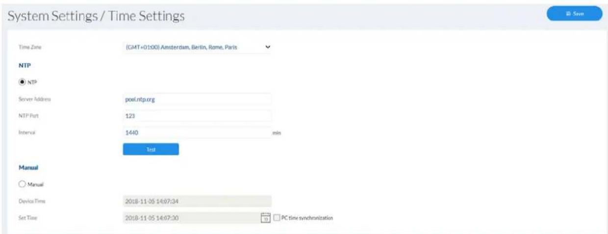
text_image
System Settings / Time Settings Time Zone (GMT+01:00) Amsterdam, Berlin, Rome, Paris NTP ● NTP Server Address pool.ntp.org NTP Port 123 Interval 1440 min Test Manual ○ Manual Device Time 2018-11-05 14:07:34 Set Time 2018-11-05 14:07:30 PC time synchronizationTime zone: here, select the time zone in which the camera is located.
NTP:
tick the box to synchronise the date and time of the camera with an NTP time server.
Server address:
enter the server address or the IP address for the NTP server here. A standard server is already set up and can be adjusted if required.
NTP port:
enter the NTP port here. The standard port for NTP is 123.
Interval:
select an update interval.
Manual:
manual setting of date and time. Click in the date/time field to open a configuration menu.
Synchronise with PC time:
use the current PC time currently being used for access (after saving the settings).
7.4.2 Daylight saving time (DST)
Enable DST: tick the box if there is generally a summer time/winter time changeover at the camera location.
Start/End time: the exact switching times can be entered here.
Daylight saving time difference: set the time difference
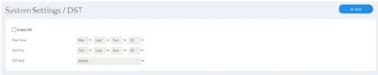
text_image
System Settings / DST Enable DST Start Time Mar Last Sun 02 End Time Oct Last Sun 03 DST Shift 60min7.4.3 Network
7.4.3.1 TCP/IP
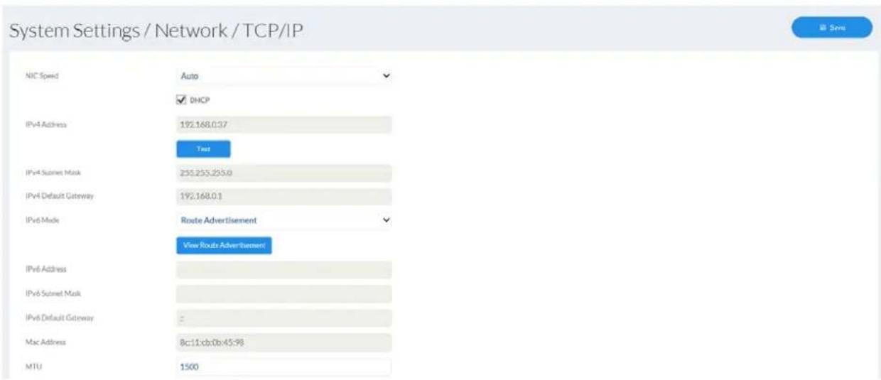
text_image
System Settings / Network / TCP/IP NIC Speed Auto ✓ DHCP IPv4 Address 192.168.037 Test IPv4 Subnet Mask 253.253.253.0 IPv4 Default Gateway 192.168.01 IPv6 Mode Route Advertisement View Routes Advertisement IPv6 Address IPv6 Subnet Mask IPv6 Default Gateway Mac Address 8c:11cb:0b:45:98 MTU 1500LAN/Wi-Fi: choose whether the Ethernet or Wi-fi interface (if available) should be configured.
NIC speed: selection of the speed for the LAN adapter.
DHCP: the IP address, subnet mask, gateway (default router) and address for the DNS server are obtained automatically from a DHCP server. An activated DHCP server must be present in the network in this case. The fields on this page are deactivated in this mode and serve as informational fields for the data obtained. If DHCP is not enabled, then a static IP address is used (see below).
Static IP address: manual setting of the network parameter for IPv4.
(DHCP checkbox not ticked)
IPv4 address: manual setting of the camera's IP address
IPv4 subnet mask: manual setting of the camera's subnet mask
IPv4 default gateway: manual setting of the camera's gateway IP address (also known as default router)
IPv6 mode: Manual: manual allocation of the IPv6 address
DHCP: automatic allocation of the address by the DHCP
Route advertisement:
IPv6 address: IPv6 network address
IPv6 Subnet Mask: IPv6 Subnet mask
IPv6 Default Gateway: IPv6 Default Gateway
MAC Address: display of the MAC address
MTU: maximum packet length
text_image
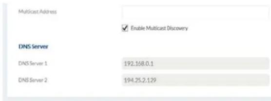
Multicast Address Enable Multicast Discovery DNS Server DNS Server 1 192.168.0.1 DNS Server 2 194.25.2.129Multicast address: multicast network address
Enable multicast: enable the multicast function
DNS server 1: manual setting of the DNS server's IP address
DNS server 2: alternative IP address of a DNS server
7.4.3.2 DDNS
Activate DDNS: ticking the checkbox activates the DDNS function.
Select service: select a service provider for the DDNS service.
Server Address: IP address of the service provider
Domain: registered host name with the DDNS service provider (if available)
Port: port for the service (if available)
User name: user account identification with the DDNS service provider
Password: account password with the DDNS service provider
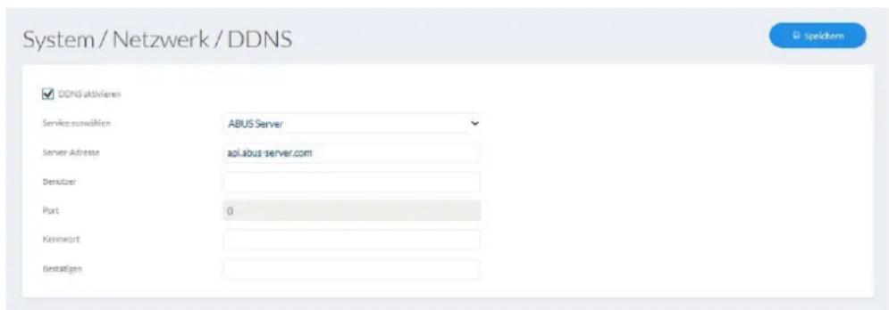
Further information on the "ABUS SERVER" can be found on the help page at the following address:
https://www.abus-server.com/faq.html
7.4.3.3 Port
HTTP port: the default port for HTTP transmission is 80. If several IP cameras are located on one subnet, each camera should have its own unique HTTP port.
RTSP port: the default port for RTSP transmission is 554. If several IP cameras are located on one subnet, each camera should have its own unique RTSP port.
HTTPS port: The default port for HTTPS transmission is 443. If several IP cameras are located on one subnet, each camera should have its own unique HTTPS port.
Server port: The default port is 8000. If several IP cameras are located on one subnet, each camera should have its own unique server port.
System Settings / Network / Port
| HTTP Port |
| RTSP Port |
| HTTPS Port |
| Server Port |
| 80 |
| 554 |
| 443 |
| 800 |
图 5.01

If the camera is to be accessed via routers (e.g. from the internet to the local network), port forwarding must be set up for the HTTP, RTSP and server port in the router. If HTTPS is also being used, port forwarding must be set up for the HTTPS port too.
7.4.3.4 NAT
Enable UPnP: enables or disables the UPnP function. When the UPnP function is enabled, the network camera can be found on Windows networks.
UPnP name: assigning a UPnP name, which the camera uses to appear on the network via UPnP.
Enable port mapping: The NAT (Network Address Translation) or port mapping function automatically sets up port forwarding for access from the Internet to the camera in the router (if the router supports this).
Mapping type: Auto: automatic assignment of all ports
Manual: manual assignment of all ports
System Settings / Network / NAT
Enable UPsP™
Narmin
Port Mapping Mode
IPCB68510-8C11CB0B4S9B
Manual
Post Type
External Port
External IP Address
Internal Port
Status
HTTP
80
0.0.0.0
50
Net Valid
RTSP
534
0.0.0.0
554
Not Valid
Server Port
8006
10.00
8000
Not Vallet
7.4.3.5 SNMP
SNMP (Simple Network Management Protocol)
The SNMP protocol enables central network management of network components.
Enable SNMPv1: enable the SNMPv1 function
Enable SNMPv2: enable the SNMPv2 function
Write SNMP Community: SNMP Community string for writing
Read SNMP Community: SNMP Community string for reading
Trap Address: IP address of the TRAP server
Trap Port: Port of the TRAP server
Trap Community: TRAP Community string
Enable SNMPv3: Enabling of SNMPv3
Read user name: Allocate user name
Security level: auth, priv: no authentication, no encryption
auth, no priv.: authentication, no encryption
no auth, no priv.: No authentication, encryption
Authentication algorithm: Select authentication algorithm: MD5, SDA
Authentication Password: Password assignment
Private-key Algorithm: Select encryption algorithm: DES, AES
Private-key password: Password assignment
Write user name: Allocate user name
Security level: auth, priv: no authentication, no encryption
auth, no priv.: authentication, no encryption
no auth, no priv.: No authentication, encryption
Authentication algorithm: Select authentication algorithm: MD5, SDA
Authentication Password: Password assignment
Private-key Algorithm: Select encryption algorithm: DES, AES
Private-key password: Password assignment
SNMP Port: Network port for the SNMP service
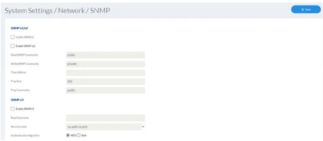
text_image
System Settings / Network / SNMP SNMP v1/v2 Enable SNMPv1 Enable SNMP v2t Read SNMP Community public Write SNMP Community private Trap Address Trap Port 162 Trap Community public SNMP v3 Enable SNMPv3 Read Username Security Level no auth, no priv Authentication Algorithm MD5 SHAAuthentication Password
Private-key Algorithm
Private-key password
Write Username
Security Level
Authentication Algorithm
Authentication Password
Private-key Algorithm
Private-key password
SNMP Other Settings
SNMPPort
......
DES AES
......
no auth, no priv
MD5 SHA
......
● DES ○ AES
•••••••
161
7.4.3.6 FTP
Server Address: IP address of the FTP server
Port: FTP server port
User name: user name for the FTP server account
Anonymous: anonymous access to the FTP server (server must support this)
Password: password for the FTP server account
Confirm: Password confirmation
Directory Structure: Select the save location for the uploaded data here. You can choose between "Save in the root directory."; "Save in the parent directory"; "Save in the child directory".
Parent directory: This menu item is only available if "Save in the parent directory" or "Save in the child directory" was selected under Directory Structure. You can select the name for the parent directory here. The files are saved in a folder on the FTP server. Choose between "Use Device Name", "Use Device Number" and "Use Device IP address".
Child directory: Select the name for the child directory here. The folder is created in the parent directory. You can choose between "Use Camera Name" or "Use Camera Number".
Picture filing interval: Options: OFF, 1-30 days
This value indicates how often a new folder is created on the FTP server for the storage of pictures (example: value 1 -> a new folder is created every day for the storage of pictures).
Make sure that the created user has rights to configure folders on the FTP server.
Picture Name: Standard: IP_Camera channel_Time stamp_Event type.jpg
User-defined prefix: Prefix_ID_Time stamp.jpg
Upload Picture: select "Upload Picture" to upload pictures to the FTP server.
Test: button for testing FTP settings
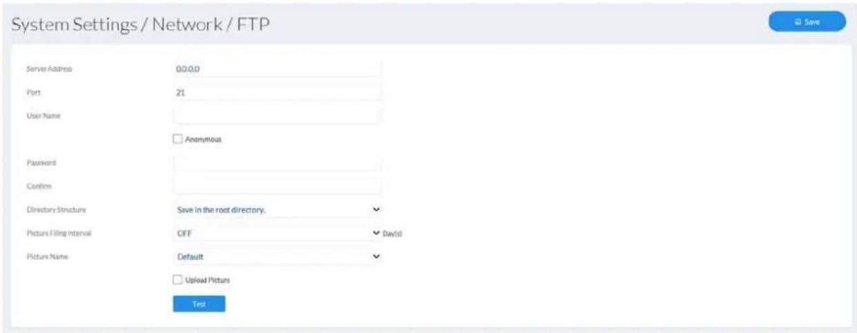
text_image
System Settings / Network / FTP Server Address 00.0.0 Port 21 User Name Anonymous Password Confirm Directory Structure Save in the root directory. Pictures Filing Interval OFF Davis Picture Name Default Upload Picture Test7.4.3.7 ABUS Link Station
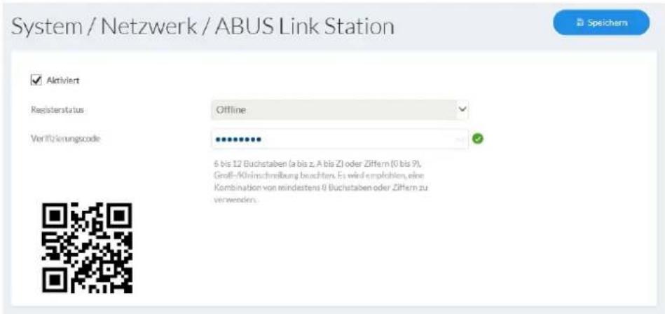
The ABUS Link Station function is used for easy remote access to the ABUS device via Link Station APP (iOS / Android). Products can be easily set up and released via QR code - without complicated configurations in the router (no port forwarding required).
Activate the function and assign a verification code (6-12 characters, A-Z, a-z, 0-9, at least 2 different character types recommended).
The QR code can then be photographed in the ABUS Link Station APP.
Push function in ABUS Link Station APP
- Activate ABUS Link Station function in IP camera
- Add IP camera via QR code or 9-digit serial number part to the ABUS Link Station app
- Enable Push Notification in APP (More / Feature Settings / Push Notification)
- Enable "Alarm Notification" in the individual camera settings in the Link Station app.
- Activate and configure desired detector in IP camera (motion detection, tripwire or intrusion detection)
- Activate "Event-controlled single-frame recording" in the IP camera under Storage / Single image recording / acquisition parameters
- Add Rule in Event Manager to IP Camera and select "Notify NVR / CMS" as action
Push result in the smartphone:
- Push info in status bar
- 1 frame under "News" in Link Station App
- optional: with built-SD card and duration or event video recording synonymous short video sequence available
7.4.3.8 HTTPS
Activate HTTPS: enables the HTTPS function. This enables a secure
connection with connection certificate. Please note that further steps are necessary for configuring the HTTPS function.
HTTPS in the browser: when enabled, the HTTPS protocol is enforced when
accessing the camera via the web browser.
Create a self-signed certificate: enter all of the details required for the certificate. When
accessing the camera at a later point, the connection must also be confirmed in the browser.
Install a signed certificate: install a HTTPS certificate from an external provider.
When accessing the camera at a later point, the connection is automatically accepted as secure (address bar shows green).

text_image
System Settings / Network / HTTPS ✓ Enable □ Enable HTTPS Browsing Certificate Details Installed Certificate C:\DE,ST\BY,L\AF,OU\abusIPcamera,H/IP=192.168.0.37 Delete Property Subject: C:\DE,ST\BY,L\AF,OU\abusIPcamera, H/IP=192.168.0.37,EM*de Issuer: C\DE,ST\BY,L\AF,OU\abusIPcamera, H/IP=192.168.0.37,EM*de Validity: 2018-10-17 11:39057.4.3.9 QoS
QoS determines the data flow between two network components on the basis of quality parameters.
DSCP - Differentiated Service Code Point
Video/Audio DSCP: DSCP value for video/audio data
Event/Alarm DSCP: DSCP value for event/alarm data
Management DSCP: DSCP value for the communication data
System Settings / Network / QoS
Video/fudio DSCP
0
Event/Blams DSCP
0
Management DSCP
0
7.4.3.10 Wi-Fi (IPCB42515A only)
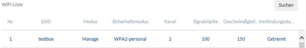
Wi-Fi list: Available Wi-Fi networks are displayed here. Click in a row to select a network.

Aktiviert
bar
WiFi-Liste | Nr. | SSID | Modus | Sicherheitsmodus | Kanal | Signalstärke | Geschwindigkei...Verbindungssta... | Suchen | |---|---|---|---|---|---|---|---| | 1 | testbox | Manage | WPA2-personal | 2 | 100 | 150 | Getrennt ↑SSID: (Service Set Identifier) Enter the name of the wireless network here.
Network mode: Infrastructure
Describes a network in which a central instance (wireless access point/router) carries out the coordination and data transmission for all network components.
Ad hoc
Describes a network in which all network components are connected to one another directly, without using a central instance (wireless access point/router). All network components must use the same SSID and security mode.
Security mode: Select encryption for the Wi-Fi connection (WPA2 personal is recommended).
Encryption Type: Select an encryption algorithm.
Password: Enter a password for the Wi-Fi network.
Enable WPS: (Wi-Fi protected setup) enables the WPS function. There are 2 different methods for using the WPS function (PIN code, PBC).
PIN code: generates a new PIN code for using the PIN code method.
PBC connection: (Push Button Configuration) the WPS connection is produced after a button is pressed on the camera.
PIN code connection: a PIN code is generated in the router and entered in the camera.
Wi-Fi
SSID
testbox
Netzwerkmodus

Manage
Sicherheitsmodus
WPA2-personal

Verschlüsselungstyp
TKIP

Schlüssel 1
Enable ONVIF: here you can disable the camera's ONVIF interface as required.
This interface is enabled by default. The access data for this interface are the same as the data for the user "installer".
System Settings / Network / Integration Protocol
2.5%
Enable ONVIF
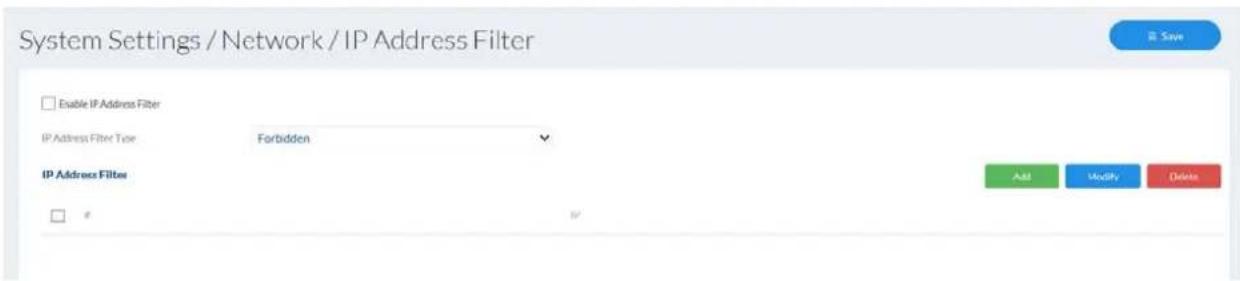
7.4.3.12 IP address filter
Enable IP address filter: enables the IP address filter function for IPv4 addresses.
Only IP addresses are allowed when inputting the addresses (no domain names).
IP address filter type: choice between forbidden and allowed addresses. You can only set either forbidden or allowed addresses.
Add/
Modify/
Delete: manage filter rules. The format for entering an IP address is:
XXX.XXX.XXX.XXX
text_image
System Settings / Network / IP Address Filter Enable IP Address Filter IP Address Filter Type Forbidden IP Address FilterB#
Add Modify Delete7.4.4 Licence information
Here, information on the code modules used under a GPL licence can be viewed.

Open Source Software Licenses
7.4.5 Update & reset
Restart: press the "Reboot" button to complete the restart manually.
Restore: resets the camera to factory settings (except network settings and user settings).
Standard: resets all settings
Device parameters: exports the entire camera configuration into a file. A password must be assigned to protect the file.
Import configuration: imports a previously exported configuration of the same camera type with a password.
Firmware update: This function can be used to update the camera's firmware.
First, download the current firmware from the ABUS website.
The "Search" button can be used to select this file for updating.
Press the "Upload" button to start the update.
Reboot
Reboot
Reboot the device.
Default
Restore
Reset all the parameters, except the IP parameters and user information, to the default settings.
Default
Restore all parameters to default settings.
Information Export
Device Parameters
Import Config File
Device Parameters
Browse
Import
Status
Upgrade
Firmware

Browse
Upgrade
Status
7.4.6 Miscellaneous
Enable IR light: By default, the integrated IR light is enabled in the cameras.
This can be permanently disabled if necessary.
Enable third stream: A third video data stream can be enabled if necessary. In such a case, this must be supported by the client (e.g. for integration via ONVIF protocol).
In this case, the "DynGOP" function will not be available in the video stream settings.
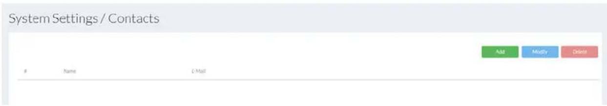
7.4.7 Contacts
This page is used to assign an email address to a name. This makes it easier to program event rules later in the Event Manager. Contacts can be added, edited and deleted.
text_image
System Settings / ContactsName E-Mail
Add Modify Delete7.4.8 Authentication
RTSP/Web Authentication: digest: User name and password are given a hash value.
digest/basic: The basic procedure encodes the password during transmission. This procedure should only be used in conjunction with HTTPS.

text_image
System Settings / Authentication RTSP Authentication dgst WEB Authentication dgst/basic7.4.9 Security
Enable illegal login lock: Enable this function to block the website for a
certain amount of time (5 min) after multiple incorrect login attempts (5).

text_image
System Settings / Security □ Enable Illegal Login Lock7.5 Video
7.5.1 Video stream
Stream: Select the 1st, 2nd or 3rd video stream for configuration (stream 3 is only available after separate activation in the system settings)
Type: Select whether video or video and audio should be transmitted.
Resolution: Choose the resolution for the video stream.
Bitrate type: Select the streaming method: Constant bitrate: keeps the bitrate constant at the set value, regardless of the quality.
Video quality: select the desired quality (for variable bitrate only). The value set here describes the compression level.
Frame rate: Select the number of images/second for transmission.
Max. bitrate: Select the maximum average bandwidth to be used. This bitrate can be exceeded for a short time in the event of corresponding image changes.
Video encoding: Select the codec that should be used for compressing the data.
Profile: Here you can select the profile type for the video codec. A profile is standardised and determines the parameters that should be used for encoding.
I frame interval: Select how often an I frame should be sent (H.264 only). The more often an I frame (full image) is sent, the better the video quality is, but the more bandwidth is required.
| Stream Type | 1st Video Stream (Normal) | ✓ |
| Video Type | Video Stream | ✓ |
| Resolution | 3840*2160 | ✓ |
| Bitrate Type | Constant | ✓ |
| Video Quality | Higher | ✓ |
| Frame Rate | 20 | fps |
| Max. Bitrate | 4096 | Kbps |
| Video Encoding | H.264 | ✓ |
| Profile | Main Profile | ✓ |
| I Frame Interval | 20 |
7.5.2 Image
Overall profile: Image settings and image optimisation functions apply for the day and night profiles
Individually time-controlled Image settings and image optimisation functions can be separately configured for day and night profiles
Brightness, contrast, saturation, hue: Adjust these values to suit the ambient conditions.
Sharpness: set the electronic oversharpening for the image (edge overdraw)
Iris mode: choose between manual and automatic iris control, depending on your model. If only one mode is available, then it is the only mode offered.
Exposure time: select a value for the fixed exposure time.
Amplification (optional): The higher the value is, the lighter the image is in poor lighting conditions and therefore the higher the image noise is.
Day/night switching: Select a method for switching between day and night mode.
Day: the camera stays in day mode.
Night: the camera stays in night mode.
Auto: Automatic switching according to light conditions
Schedule: switching at fixed times. You must enter the day start time and day end time.
Triggered by event: switching is performed by triggering the switching input. The output status can be achieved via the status option if the input is not triggered.
Sensitivity: the higher the value is, the darker it must be for the camera to switch to night mode.
Delay time: delay in seconds until switching to day or night mode.
Smart IR: Prevents glare effects from objects that are too close when IR lighting is enabled.
WDR: wide dynamic function for improved display of high contrasts.
The WDR level should be reduced if the image displayed is too bright.
Wide dynamic level: select the WDR level. A higher level may increase image noise.
HLC: Glare around the edge of bright light sources is reduced (e.g. car headlights). A higher threshold means high reduction. Function only with deactivated WDR.
White balance: Select between different variants of white balance.
Digital Noise reduction: Function for reducing noise in the image. The higher the value, the more noise is removed and the more static the image appears.
Noise reduction level: select the DNR level
Mirroring: H: Horizontal mirroring (left/right)
V: Vertical mirroring (up/down)
Hor. + Vert.: Horizontal and vertical mirroring
Vertical display: This setting rotates the image to increase the vertical angle of view. It is necessary to rotate the camera module by 90^ when doing this.
Scenario pre-settings: These two indoor/outdoor options are used to configure certain pre-settings for the two scenarios in the camera.
Video standard: Here you can set the mains frequency of the power supply network.
Scheduled Image Settings
Auto-Switch

^ Image Adjustment
Brightness
Contrast
Saturation
Sharpness

bar
| Value | |---| | 50 | | 50 | | 50 | | 40 |√ Exposure Settings
Day/Night Switch
Backlight Settings
√ White Balance
√ Image Enhancement
√ Video Adjustment
7.5.3 OSD
Text: superimposes the configurable camera name on the live image.
Date: superimposes the date on the live image.
Camera name: enter the camera name here (max. 32 characters).
Time format: select a display format (24-hour or 12-hour) for the time.
Date format: select a display format for the date.
Display mode: select between flashing or non-flashing display for all overlays.
OSD size: select the size for a character. Options: 16x16, 32x32, 48x48,
64x64 pixels, auto). The auto option automatically adapts the character size to the image size.
Font colour: select the colour for displaying characters. The colour palette for a custom selection can be found on the right next to the selection box.
□ Display Name
□ Display Date
Camera Name
ABUS IP Camera
Time Format
24-hour
Date Format
DD-MM-YYYY
Text OverLay
□ 1
□ 2
□ 3
□ 4
Display Mode
OSD Size
Font Color
Not transparent & Not flashing
Auto
Custom
V
V
V


7.5.4 Privacy mask
Preview area: The preview of the video and privacy masks that have been set up are displayed here. Privacy masks are drawn directly in the preview area.
Enable privacy mask: Enable/disable the privacy mask function.
Draw Area: Draw polygonal areas. The drawing mode is closed by pressing this button again. The area drawn is blacked out and so cannot be seen in the live image or in the recording.
Delete all: Delete a privacy mask

Enable Privacy Mask
Draw Area
Clear All
7.6 Audio
Audio encoding: select the audio encoding for audio transmission here (G.722.1, G.711ulaw, G.711alaw, MP2L2, G.726).
Audio input: enables the audio input (only for cameras with built-in microphone and microphone input).
Input volume: adjustment of the input amplification for the microphone.
Environmental noise filter: enable the digital noise reduction function for audio transmission here.

Post-record: determine how long a video should be saved for after an event.
Overwrite: Determine the behaviour if an SD card/NAS is full (end recording or replace oldest data with new data = cycle recording function).
Video stream: Select the video stream for recording.
Elapsed time: Set the number of days until the data are overwritten.
Enable record schedule: after enabling and configuration, video data are either saved constantly or at certain times and if necessary when an event occurs. The schedule can be configured using the Edit button.

Enable
Advanced Configuration


Overwrite
Post-record
5 s

Stream Type
1st Video Stream (Normal)

Expired Time
3
Day(s)
OK
Cancel
7.7.2 Single frame recording
After enabling and configuration, single frames can be saved on the SD card. The single frames can be saved in a time-controlled and/or event-controlled manner.
Enable sequential single frame recording: You can determine the schedule for storage here.
Enable snapshot timing: enables time-controlled storage.
Format: available image formats for the single frames: JPEG
Resolution: available resolutions for the single frames: 1920x1080
Quality: available quality for the single frames: 3 levels
Interval: you can determine the save intervals (min. 1 second, max. 7 days) here.
Enable event-triggered snapshot: after enabling, single frames are saved to the SD card if an event occurs (e.g. motion detection, cover detection)
Number of images:
here you can define the number of images saved after an event (1-120).
Capture Schedule Capture Parameters
Timing
□ Enable Timing Snapshot
| Format | JPEG | |
| Resolution | 3840*2160 | |
| Quality | High | |
| Interval | 1000 | milliseconds |
Event-Triggered
□ Enable Event-Triggered Snapshot
| Format | JPEG | |
| Resolution | 3940*2160 | |
| Quality | High | |
| Interval | 1000 | milliseconds |
| Capture Number | 4 | |
7.7.3 Storage management
Device list: indicates the available storage media in the camera (SD card).
Format: formats the selected storage medium (Attention: all data are deleted).
Information: shows more storage medium information.
Quota
Max.Picture Capacity
3.50GB
Free Size for Picture
3.50GB
Max. Record Capacity
10.75GB
Free Size for Record
0.00GB
Percentage of Picture
25
Percentage of Record
75
%
%
HDD Management
Format

HDD No.
Capacity
Free space
Status
Type
Property
Progress

1
14.84GB
3.50GB
Normal
Local
R/W
7.7.4 Network drive
NAS: configure up to 8 NAS devices. Click in a row to specify server address, file path, server type, user name and password.
Net HDD
| HDD Nos. | Sewer Allentos | Tile Pads | Type | Delete |
| 1 | NAS | × | ||
| 2 | NAS | × | ||
| 3 | NAS | × | ||
| 4 | NAS | × | ||
| 5 | NAS | × | ||
| 6 | NAS | × | ||
| 7 | NAS | × | ||
| 8 | NAS | × |
7.8 Local settings
Protocol: Setting the transmission protocol (default: TCP)
Live view performance: Select the priority for display in the browser here (priority on image stream or image quality).
Live indicator: Display of all event animations in the live image (e.g. frame for motion detection). These animations are also recorded to the recording device.
Image format: Select the encoding format for saving single frames using the browser live interface.
Record file size: Select the size of video sequences for saving videos using the browser live interface.
Save record files to: Select the path for video recording.
Save downloaded files to: Select the path for video files downloaded from the SD card.
Save live snapshots to: Select the encoding format for saving images using the browser live interface.
Snapshots during playback: Select the path for saving images during playback.
Save clips to: Select the path for saving video clips during playback.
Live View Parameters
| Protocol | TCP | UDP | MULTICAST | HTTP |
| Live View Performance | Shortest Delay | Balanced | Fluent | |
| Live indicator | Enable | Disable | ||
| Display POS Information | Enable | Disable | ||
| Image Format | JPEG | BMP | ||
| Record File Settings | ||||
| Record File Size | 256M | 512M | 1G | |
| Save record files to | C:\Users\Agentur\Web\RecordFiles | Browse Open | ||
| Save downloaded files to | C:\Users\Agentur\Web\DownloadFiles | Browse Open | ||
| Picture and Clip Settings | ||||
| Save snapshots in live view to | C:\Users\Agentur\Web\CaptureFiles | Browse Open | ||
| Save snapshots when playback to | C:\Users\Agentur\Web\PlaybackPics | Browse Open | ||
| Save clips to | C:\Users\Agentur\Web\PlaybackFiles | Browse Open | ||
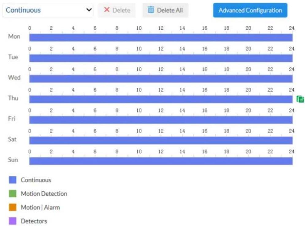
7.9 Schedules
Here up to 10 different schedules can be configured for later use in the Event Manager. The "Add" button is used to open the input mask for the configuration of the schedule.

text_image
F Name Schedule 1 24h Mon.Tue.Wed.Thu.Fri.Sat.Sun. 2 MQ Mon.Tue.Wed.Thu.Fri.Sat.Sun. 3 TD Mon.Tue.Wed.Thu.Fri.Sat.Sun. 4 ID Mon.Tue.Wed.Thu.Fri.Sat.Sun. 5 SCD Mon.Tue.Wed.Thu.Fri.Sat.Sun.7.10 Detectors
7.10.1 Motion detection
Enable motion detection: enables motion detection.
Enable dynamic analysis for motion: if enabled, changes to the video image content are displayed graphically in the preview.
NOTE: The LIVE INDICATOR function decides whether this should also be displayed in the live image.
Preview area: preview and configuration area.
Draw Area: draw areas here (max. 8), which should be monitored by motion detection. Operation: Press button -> draw rectangle in the preview using left mouse button -> press button again to finish drawing.
Delete: delete all areas.
Mode: Switch between Normal and Expert mode
Normal: basic sensitivity settings
Expert: sensitivity and object size ("percentage") can be configured, a profile can be applied per schedule, 8 areas
Day/night switching: defines how motion detection is applied during the day or night mode.
Off: settings for day and night are identical.
Automatic switching: settings are automatically coupled to automatic day/night switching.
Schedule: settings for day and night are applied according to a schedule.
Sensitivity: determines the required intensity of the pixel change. The higher the value, the fewer pixel changes are required to trigger motion.
Percentage: [only in expert mode] object size required for triggering motion in the area (0–100%).

Enable Motion Detection

Enable Dynamic Motion Indicator
Configuration
Normal

Draw Area
Clear All
Sensitivity

7.10.2 Cover detection
Enable cover detection: This function monitors the covering of an area in the video image.
Preview: Preview and configuration area.
Drawing: This allows you to draw the area which should be monitored by
cover detection. Operation: Press button -> draw rectangle in the preview using left mouse button -> press button again to finish drawing.
Delete: Deletes the area.
Sensitivity: Change the sensitivity of the detection here (3 levels).


Sensitivity

7.10.3 Alarm input
Alarm Input No.: Select the alarm input to be configured here (number depends on camera model).
Alarm name: enter the name here.
Alarm type: the alarm type determines the idle and triggered statuses.
NO: normally open (normal status open)
NC: normally closed (normal status closed)
Enable alarm input processing: The alarm input can only be used when the checkbox is ticked.
Alarmeingang Nr.
A<-1
V
IP Adresse
Lokal
Alarmtyp
N.O
V
Alarmname

7.10.4 Scene change detection
Enable scene change detection: This function detects whether the content of the image has changed significantly. Any turning of the camera can therefore be detected.
Sensitivity: The higher the value, the smaller the changes to the image content need to be in order to trigger an alarm.

Enable
Sensitivity

50
7.10.5 Intrusion detection
Enable intrusion detection: The intrusion detection function triggers an event if an object stays in the area to be monitored for longer than the set time.
Preview video: configure the area to be monitored
Draw Area: The area to be monitored can be drawn in the video image (quadrilateral area). Operation: press button -> set corner points using left mouse button (max. 4) -> press button again to finish drawing
Delete: delete the area.
Area: Number of available areas: 1
Threshold: The higher the value (0-10 seconds), the longer an object has to stay in the area to be monitored in order to trigger an event.
Sensitivity: higher sensitivity allows smaller objects to be detected.
Percentage: this value decides how much of an area must be covered by an object in order to trigger an event. The larger the value, the more of an area has to be covered.

text_image
Max. Size Min. Size Draw Area Clear Threshold Sensitivity 4 507.10.6 Tripwire detection
Enable tripwire: The tripwire function detects whether an object crosses a virtual line in the video image in a certain direction or both directions. Then, an event can be triggered.
Preview video: configure the virtual line here.
Max. size:
This function determines the maximum size of the object to be detected. This is done by drawing a rectangle in the preview video. The rectangle can be drawn anywhere in the preview video.
Min. size: This function determines the minimum size of the object to be detected. This is done by drawing a rectangle in the preview video. The rectangle can be drawn anywhere in the preview video.
Drawing: a virtual line appears in the preview video after the button is pressed. It is then possible to click on this line and move it using the mouse and the red corner points. "A" and "B" indicate the directions.
Delete: delete the virtual line
Virtual plane: number of available virtual lines: 1
Direction: definition of the direction(s) in which an object crosses and triggers an event.
Sensitivity: The higher the value, the earlier a crossing object is detected.
text_image
Max. Size Min. Size Draw Area Clear Direction A<->B Sensitivity 507.11 Outputs
Alarm output: Select the alarm output to be configured here (number depends on camera model).
Alarm name: enter the name here.
Delay: select the duration of switching output activity in the event of an alarm.
Manual: The output is only activated for as long as the event lasts.
Alarm Status: Displays the current status of the alarm output.
bar
| Alarm Status | 0 | 2 | 4 | 6 | 8 | 10 | 12 | 14 | 16 | 18 | 20 | 22 | 24 | |---|---|---|---|---|---|---|---|---|---|---|---|---|---| | Mon. | 0 | 2 | 4 | 6 | 8 | 10 | 12 | 14 | 16 | 18 | 20 | 22 | 24 | | Die. | 0 | 2 | 4 | 6 | 8 | 10 | 12 | 14 | 16 | 18 | 20 | 22 | 24 | | Mi. | 0 | 2 | 4 | 6 | 8 | 10 | 12 | 14 | 16 | 18 | 20 | 22 | 24 | | Don. | 0 | 2 | 4 | 6 | 8 | 10 | 12 | 14 | 16 | 18 | 20 | 22 | 24 | | Fr. | 0 | 2 | 4 | 6 | 8 | 10 | 12 | 14 | 16 | 18 | 20 | 22 | 24 | | Sa. | 0 | 2 | 4 | 6 | 8 | 10 | 12 | 14 | 16 | 18 | 20 | 22 | 24 | | So | 0 | 2 | 4 | 6 | 8 | 10 | 12 | 14 | 16 | 18 | 20 | 22 | 24 | Manueller Alan Kopieren nach...7.12 Users
7.12.1 Managing users
Add/edit/delete: Users with the type "Master" and "User" can be added.
User name: Enter the user names here (max. 32 characters, not allowed: \ : ").
Language: Select the language to be displayed for the user here.
Use a secure password:
A secure password must meet the following minimum requirements:
- 8–16 characters
- Valid characters: numbers, lower-case letters, capital letters, special characters ( ! \$ % & / ( ) = ? + - )
- You must use at least two different types of character
Password/confirm: Enter and confirm the password here.

text_image
User List Add Modify DeleteUser Name Level Language
1 installer Installer English
The home page and login window are displayed in the language of the PC as long as this language is available in the camera. If the language is not available, it will be displayed in English.
7.12.2 Online users
Displays information about the currently logged-on user.
| User List | ||||
| No. | User Name | Level | IP Address | User Operation Time |
| 1 | Installer | Installer | 192.168.0.24 | 2018-11-05 14:22:04 |
7.13 Email
The SMTP/email function must be configured beforehand, so that the camera is able to send emails if certain events occur. You can obtain information about the various details from your email provider.
Sender: Enter the name of the sender here.
Sender's address: Enter the email address of the sender here.
SMTP Server: Enter the SMTP outgoing mail server for your email provider here.
SMTP port: Enter the SMTP server port here (e.g. 587 if you are using TLS).
Email encryption: enable if the email server uses SSL or TLS. The SMTP port may have to be changed.
Attached Image: Choose an image interval for attached images. / Option must be enabled for attached images.
Authentication/
User name/
Password: Enable this option if the SMTP email server requires
authentication. Enter the user name and password and confirm the password for the account for sending email.
Sender
Sender's Address
SMTP Server
SMTP Port
E-mail Encryption

Attached Image
Interval

Authentication
User Name
Password
Confirm
Test Email
25
None
2

∨s

Test
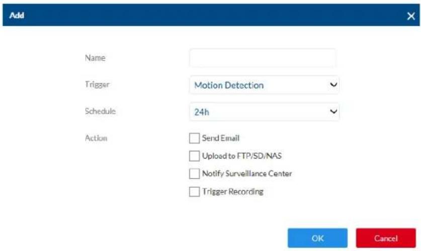
7.14 Event Manager
Trigger: an alarm rule consists of a trigger, a schedule for applying the rule and an action. Select a trigger for the alarm rule from the list. Only one trigger can be configured for each rule.
Schedule: an alarm rule can be enabled in 30 minute intervals. This is highlighted directly in the matrix on the left (red = enabled).
Action: one or more actions can be defined for the rule on this page.
| # | Name | Trigger | Schedule | Action |
| 1 | MD | Motion Detection | MD | Trigger Recording || Audible Warning || Notify Surveillance Center |
| 2 | TD | Tripwire Detection | TD | Notify Surveillance Center |
| 3 | ID | Intrusion Detection | ID | Notify Surveillance Center |
| 4 | SCD | Scene Change Detection | SCD | Notify Surveillance Center |
text_image
Add Name Trigger Motion Detection Schedule 24h Action Send Email Upload to FTP/SD/NAS Notify Surveillance Center Trigger Recording OK Cancel8. Maintenance and cleaning
8.1 Function test
Regularly check the technical safety of the product, e.g. check the housing for damage.
If it appears to no longer be possible to operate the product safely, stop using it and secure it to prevent unintentional use.
It is likely that safe operation is no longer possible in the event that:
- the device shows signs of visible damage
- the device no longer works correctly
• the device has been stored in adverse conditions for a long period of time - the device has been exposed to stresses during transportation.

Please note:
You do not need to perform any maintenance on the product. There are no components requiring servicing or checking inside the product. Never open it.
8.2 Cleaning
Clean the product with a clean, dry cloth. The cloth can be dampened with lukewarm water to remove stubborn dirt.

Make sure that no liquids enter the inside of the device, as this will destroy it. Do not use any chemical cleaning agents, as these could damage the surface of the housing.
9. Disposal

Devices displaying this symbol may not be disposed of with domestic waste. At the end of its service life, dispose of the product according to the applicable legal requirements. Please contact your dealer or dispose of the products at the local collection point for electronic waste.
IPCB42510A / IPCB42510B / IPCB42510C / IPCB42515A /
IPCB44510A / IPCB44510B / IPCB44510C / IPCB62510A /
IPCB62510B / IPCB62510C / IPCB64510A / IPCB64510B /
IPCB64510C / IPCB68510A / IPCB68510B / IPCB68510C /
IPCB62515A / IPCB64515B / IPCB68515A / IPCB72515A /
IPCB74515B / IPCB78515A / IPCB74615B / IPCB78615A
natural_image
Exterior view of a white car parked inside a modern parking garage (no signage)6.1 Configuration locale
text_image
http://192.168.0.100 OBUS Network Camera ? Logged In as Installer7.3 Tableau de bord
7.4.3.6 ABUS Link Station
C=DE,ST=BY,L=AF,OU=abusIPcamera,H/IP=192.168.0.37
Supprimer
Thème: C=DE, ST=BY, L=AF, OU=abusIPcamera.
H/IP=192.168.0.37,EM=de
DSCP - Differentiated Service CodePoint
Flux principal (normal)

Type de vidéo
Flux vidéo

Résolution
3840*2160

bar
| Category | Count | |---|---| | Mon. | 0 | | Die. | 0 | | Mi. | 0 | | Don. | 0 | | Fr. | 0 | | Sa. | 0 | | So | 0 |7.12 Utilisateur
IPCB42510A / IPCB42510B / IPCB42510C / IPCB42515A /
IPCB44510A / IPCB44510B / IPCB44510C / IPCB62510A /
IPCB62510B / IPCB62510C / IPCB64510A / IPCB64510B /
IPCB64510C / IPCB68510A / IPCB68510B / IPCB68510C /
IPCB62515A / IPCB64515B / IPCB68515A / IPCB72515A /
IPCB74515B / IPCB78515A / IPCB74615B / IPCB78615A

text_image
http://292.168.0.100/doc/page/config.asp ABUS Network Camera ? Logged in as Installer7.3 Dashboard
text_image
MEMORY USED 88%
text_image
CPU LOAD 33%
text_image
TRAFFIC 130kV/sRoute Advertisement weingever
IPv6 adres
IPv6 subnetmasker
IPv6 Standard Gateway
MAC-adres
MTU
Multicast-adres

8c:11:cb:0b:45:98
1500
Trap Community: TRAP Community string
SNMPv3 activeren: Activering van SNMPv3
Private Key algorithm
no auth, no priv
MDS SHA
●●●●●
DES AES
7.4.3.6 FTP
Serveradres: IP-adres van FTP-server
7.4.3.7 ABUS Link Station
C=DE, ST=BY, L=AF, OU=abusIPcamera, H/IP=192.168.0.37
Wissen
Thema: C=DE, ST=BY, L=AF, OU=abusIPcamera,
H/IP=192.168.0.37,EM=de
Ultgever: C=DE, ST=BY, L=AF, OU=abusIPcamera,
H/IP=192.168.0.37, EM=de
Geldigheid: 2018-10-17 11:39:05
7.4.3.9 QoS
DSCP - Differentiated Service CodePoint
Opensource softwarelicenties
7.4.5 Upgrade en resetten
text_image
Torsorgen Wilggen WilsenAlias Schedules
1 24h Mon Tue Wed Thu Fri Sat Sun 2 MD Mon Tue Wed Thu Fri Sat Sun 3 TD Mon Tue Wed Thu Fri Sat Sun 4 ID Mon Tue Wed Thu Fri Sat Sun 5 SCD Mon Tue Wed Thu Fri Sat Sun7.10 Detectoren
IPCB42510A / IPCB42510B / IPCB42510C / IPCB42515A /
IPCB44510A / IPCB44510B / IPCB44510C / IPCB62510A /
IPCB62510B / IPCB62510C / IPCB64510A / IPCB64510B /
IPCB64510C / IPCB68510A / IPCB68510B / IPCB68510C /
IPCB62515A / IPCB64515B / IPCB68515A / IPCB72515A /
IPCB74515B / IPCB78515A / IPCB74615B / IPCB78615A
4.6 Startside (login-side)
text_image
http://192100.0.ST/doc/target/cnfrig.wmp ABUS Network Camera FORESIDE LiveView Playback GENERAL Local ? Logged in as master 1 ● REC + -text_image
http://192.168.0.37/doc/page/config.asp ABUS Network Camera FORSIDE LiveView Playback Dashboard Systemlog GENEROLT System Video Lagging Local Schedules DETEKTORER & UDGANGE Event BRUGER User Manager KOMMIMINATION Logged in as installer REC +(Eksempel: IPCB42515A)
text_image
https://192.168.0.100.doc/page/config.asp ABUS Network Camera ? Logged in as Installer7.3 Dashboard
Dashboardet viser generelle informationer om kameraet, f.eks. installeret firmware-version eller kameraets serienummer.
ABUS Network Camera
Model
IPCB68510
Serienr.
IPCB6851020180704AAWR865079325
Firmware-version
V5.5.52 bulld 180912
Kodningsversion
V7.3 build 180622
Webversion
V4.0.51 bulld 180911
Plugin-version
V3.0.6.4302
Arital kanalar
1
AntalHDD
1
Antal alarm mind range
0
Antal alarmudgange
0
Firmwareversion
C-R-G1-0

text_image
SYSTEM STATUS OK
text_image
MEMORY USED 85%
bar
| Category | Value (%) | |---|---| | CPULOAD | 32 |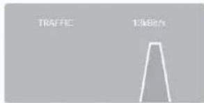
text_image
TRAFFIC 1.3462/s7.4.3.7 ABUS Link Station
DSCP – Differentiated Service CodePoint
Video/audio-DSCP: DSCP-værdi for video-/audiodata
Open Source software licenser
Main stream (normal)
V
Videotype
Video-stream
V
Opløsning
3840*2160
v
Bitrate-type
Konstant
v
Videokvalitet
Hoj
∨
Billedhastighed
20
fps
Maks. bitrate
4096
Kbps
Videokodning
H.264
√
Profil
Hovedprofil
V
|-frame Interval
20
Gem
7.5.2 Billede
NC: Normally Closed (normaltilstand lukket)