A8008 - Motion detector DoorBird - Free user manual and instructions
Find the device manual for free A8008 DoorBird in PDF.

| Product type | 4D radar motion detector |
| Brand | DoorBird |
| Model | A8008 |
| Dimensions | 33 x 70 x 70 mm (L x W x D) |
| Weight | 67.5 g (device) + 10 g (wall adapter) |
| Power supply | 5-48 V DC, max. 1 W (power adapter not included) |
| Protection rating | IP65 |
| Material | Polycarbonate |
| Detection technology | 4D, based on 24 GHz RF sensor |
| Detection angle | 54° horizontal, 70° vertical |
| Range | 1 to 10 m (adjustable) |
| Detection modes | Coming, Leaving, Both, Off |
| Settings | Sensitivity, relay duration (0 ms - 15 min), LUX threshold |
| Relay | 1 bistable relay 24 V DC/AC 1 A, 1 MOSFET relay 48 V DC/AC 1 A |
| Operating conditions | -25°C to +55°C, humidity 0-85% non-condensing |
| Certifications | CE, FCC, IC, RoHS, REACH, WEEE |
| Package contents | Detector, manual, 2 cables, wall mount, small parts |
| Maintenance and cleaning | No maintenance required. Clean with a soft, dry cloth. |
| Safety | Installation by a competent adult. Minimum distance of 20 cm from body. |
| Repairability | No user repairs possible. Contact customer service. |
Frequently Asked Questions - A8008 DoorBird
User questions about A8008 DoorBird
0 question about this device. Answer the ones you know or ask your own.
Ask a new question about this device
Download the instructions for your Motion detector in PDF format for free! Find your manual A8008 - DoorBird and take your electronic device back in hand. On this page are published all the documents necessary for the use of your device. A8008 by DoorBird.
USER MANUAL A8008 DoorBird

Page 2-11
Installation Manual
4D Security Radar
Motion Sensor A8008

Seite 12-20
Read these instructions carefully before starting Installation manual
Keep the manual so you can refer to it at a later date if required. If you hand over the device to other persons for use, please hand over the operating manual as well.
You can always find the most up-to-date version of the installation manual on www.doorbird.com/support To make things easier we use the term "device" for the product "4D Security Radar Motion Sensor A8008" and "mobile device" for a smartphone or tablet.
Liability
Every care has been taken in the preparation of this document. Please inform Bird Home Automation GmbH of any inaccuracies or omissions. Bird Home Automation GmbH cannot be held responsible for any technical or typographical errors and reserves the right to make changes to the product and manuals without prior notice. Bird Home Automation GmbH makes no warranty of any kind with regard to the content of this document, including, but not limited to, the implied warranties of merchantability and fitness for a particular purpose. Bird Home Automation GmbH shall neither be liable nor responsible for incidental or consequential damages in connection with the furnishing, performance or use of this material. This product is only to be used for its intended purpose.
Equipment Modifications
This equipment must be installed and used in strict accordance with the instructions given in the user documentation. This equipment contains no components that require service by the user. Unauthorized equipment changes or modifications will invalidate all applicable regulatory certifications and approvals.
Symbols used

Danger: Indicates a hazardous situation which, if not avoided, will result in death or serious injury.

Warning: Indicates a hazardous situation which, if not avoided, could result in death or serious injury.

Caution: Indicates a hazardous situation which, if not avoided, could result in minor or moderate injury.

Notice: Indicates a situation which, if not avoided, could result in damage to property.

Important: Indicates significant information which is essential for the product to function correctly.

Note: Indicates useful information which helps in getting the most out of the product.
FCC Statement
This equipment has been tested and found to comply with the limits for a Class B digital device, pursuant to part 15 of the FCC Rules. These limits are designed to provide reasonable protection against harmful interference in a residential installation. This equipment generates, uses and can radiate radio frequency energy and, if not installed and used in accordance with the instructions, may cause harmful interference to radio communications. However, there is no guarantee that interference will not occur in a particular installation. If this equipment does cause harmful interference to radio or television reception, which can be determined by turning the equipment off and on, the user is encouraged to try to correct the interference by one or more of the following measures:
- Reorient or relocate the receiving antenna.
- Increase the separation between the equipment and receiver.
- Connect the equipment into an outlet on a circuit different from that to which the receiver is connected.
- Consult the dealer or an experienced radio/TV technician for help.
Caution: Any changes or modifications to this device not explicitly approved by manufacturer could void your authority to operate this equipment.
This device complies with part 15 of the FCC Rules.
Operation is subject to the following two conditions:
(1) This device may not cause harmful interference, and (2) this device must accept any interference received, including interference that may cause undesired operation.
RF Exposure Information
This equipment complies with FCC radiation exposure limits set forth for an uncontrolled environment. This equipment should be installed and operated with minimum distance 20cm between the radiator and your body.
ISED Statement
English: This device contains licence-exempt transmitter(s)/receiver(s) that comply with Innovation, Science and Economic Development Canada's licence-exempt RSS(s). Operation is subject to the following two conditions:
(1) This device may not cause interference.
(2) This device must accept any interference, including interference that may cause undesired operation of the device.
The digital apparatus complies with Canadian CAN ICES-3 (B)/NMB-3(B).
This device meets the exemption from the routine evaluation limits in section 2.5 of RSS 102 and compliance with RSS 102 RF exposure, users can obtain Canadian information on RF exposure and compliance.
This equipment complies with Canada radiation exposure limits set forth for an uncontrolled environment.
This equipment should be installed and operated with minimum distance 20 cm between the radiator & your body.
Please observe the warnings and safety instructions in our accompanying booklet:
https://www.doorbird.com/downloads/warnings.pdf
COMPONENTS

1x Installation manual1x 4D Secu
Motion Sensor A8008
natural_image
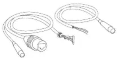
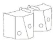
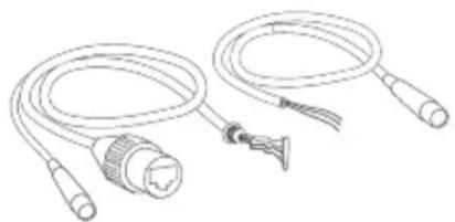
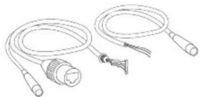
Line drawing of two coiled electrical cables with connectors and a connector (no text or symbols)2x Connection cable, only required if you want to connect the device to the DoorBird A1131 IP Video Mini Dome Camera.

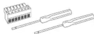
1x Screw connection terminal plug and
2x Screw driver
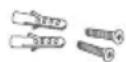
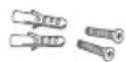
2x Phillips countersunk head screws and dowels
1x Wall mount adapter
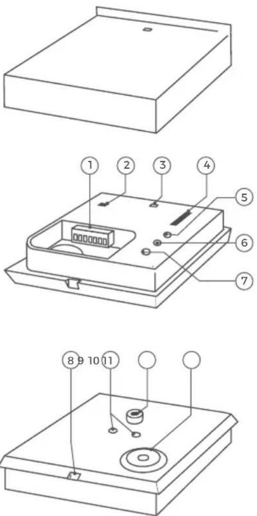
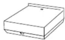
DEVICE
Inside
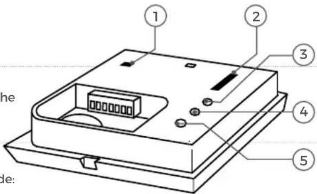
1) Relay 1/X, Input Connections for relays and power supply
2) LED on/off
Switch to deactivate the Motion LED
3) Motion LED - Display of the detected movement
4) Motion detection - Switch to choose motion detection mode
Off = No motion detection
Coming = Detect only approaching motion events
Leaving = Detect only distant motion events
Coming/Leaving = Detect approaching and distant motion events
5) Lux Rotary control to set the day/night switchover
6) Time Relay 1 0 ms - 15min - Rotary control to set the switching time of relay 1
7) Sensitivity -/+ Rotary control to set the sensitivity (distance) for the motion detection
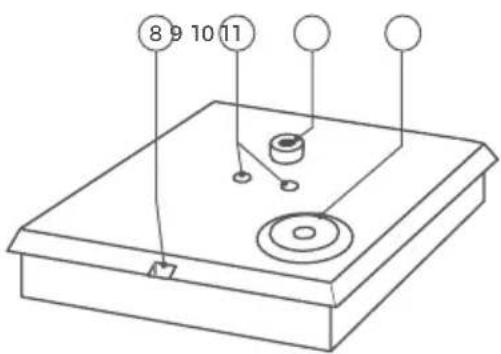
Back
8) Cover hole - Hole to remove cover via slotted screwdriver
9) Mounting holes - Mounting holes for enclosed wall bracket
10) Tripod socket - 1/4' tripod socket for wall alternative mount adapter
11) Cable entry - Sealed cable entry for connection cable
VIDEOS
Need help with the installation? Be sure to watch our installation videos which can be found on http://www.doorbird.com/support
INSTALLATION
All the steps below should be carried out carefully by a competent adult, taking into consideration any applicable safety regulations. Please contact us directly or seek the advice of a competent specialist.

Please ensure that all wires used for the installation are undamaged along their entire length and approved for this type of use.
1
SWITCHING OFF POWER

Switch off the power to all wires leading to the assembly location, i.e. the door chime, electric door opener, power supply unit for the device etc.
2
DETERMINING THE ASSEMBLY LOCATION

The device is IP65 rated. Make sure to put the device into a suitable location.
3
MOUNTING THE DEVICE
The device can be mounted on the wall using the wall mount adapter, screws and dowels supplied with it. Alternatively you can mount it via tripod socket on your own tripod.
OPTION 1
Wall mounting

Ensure not to hit any objects (e.g. cables) when drilling the holes.
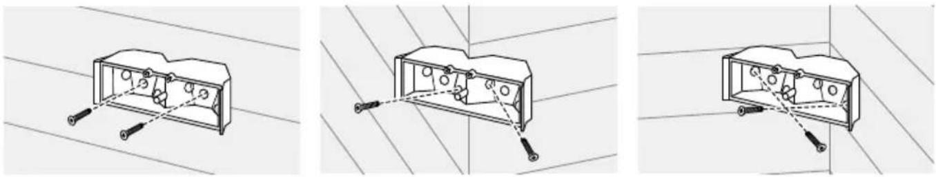
natural_image
Three technical line drawings of an electrical outlet box with mounting holes and wiring (no text or symbols)If the wall of the house is not made of wood, you should drill dowel holes 5 mm (0.196 in) in diameter in the wall and then place the dowels provided into the boreholes. If the wall of the house is made of wood, you will usually not require any dowels. There are special dowels for assembling the device on an insulating wall, e.g. Fischer insulating dowels. Please check with your insulating material manufacturer regarding which dowels they recommend.
natural_image
Diagram showing a device being adjusted to a screen, with a magnified inset highlighting the screen's adjustment (no text or symbols present)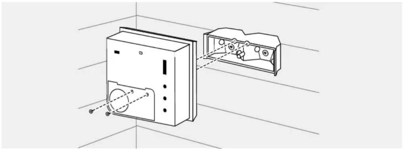
natural_image
Technical line drawing of a device with two views: one showing internal components and the other showing external housing (no text or symbols)OPTION 2
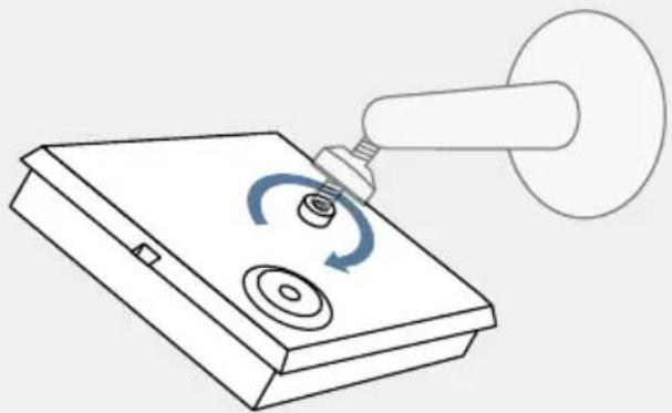
Tripod mounting
The device can be mounted on a tripod. Use the tripod socket on the back of the unit (standard tripod thread according to DIN 4503-1 / ISO 1222).
Tripod is not included in the scope of delivery.
natural_image
Line drawing of a mechanical device with a rotating knob and a handle, no text or symbols present4
POWER SUPPLY
The device can be supplied with power via a separate power supply unit (5 - 48 V DC, power consumption max. 1W), not included in the scope of delivery.
If you are pairing the device with the DoorBird A1131 IP Video Mini Dome Camera, a special connection cable with a socket (type: M8 3P) at one end of the cable is included. This cable allows the DoorBird A1131 IP Video Mini Dome Camera to both supply the device with power and receive alarm signals from it. The DoorBird A1131 IP Video Mini Dome Camera then provides the necessary power supply via the red and black wires of the connection cable.

Do not connect the device to a power supply yet.
5
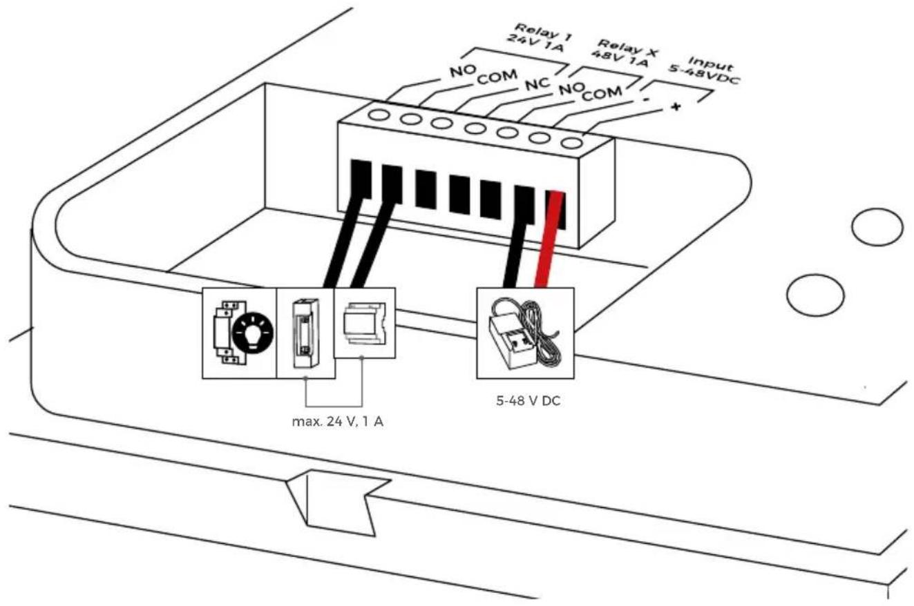
CONNECTING THE DEVICE
The device is designed to switch any standard contacts in the low-voltage range of 24 V DC/AC, 1 A, e.g., for alarm contacts, light controls, etc. If you want to use a device with more than 24 V DC/AC, such as a lamp or door opener with 110-240 VAC, you need an additional switching relay with 110 - 240 V AC, as the device is only designed for a maximum of 24 V DC/AC.
The wires of the connection cable can be conveniently and securely connected to the labeled screw terminal on the device. You can now connect all the necessary wires to the device.

Please remove any cables and wires from the connection ports of the device that you do not need.

Please take care when connecting the cables and wires. Connecting the cables and wires the wrong way may damage the device.
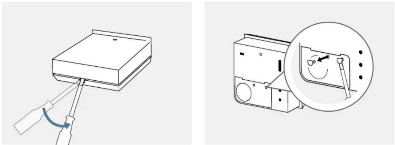
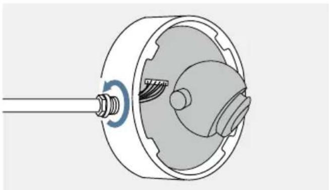
natural_image
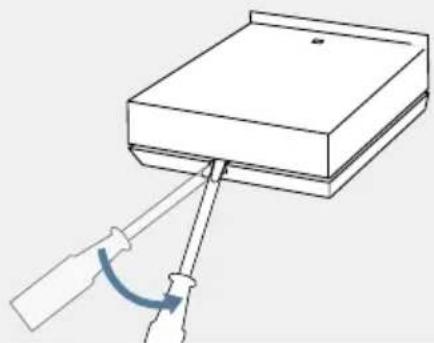
Diagram of a screwdriver inserted into a rectangular block with a curved arrow indicating rotation (no text or symbols)Lever off the cover with a screwdriver.
natural_image
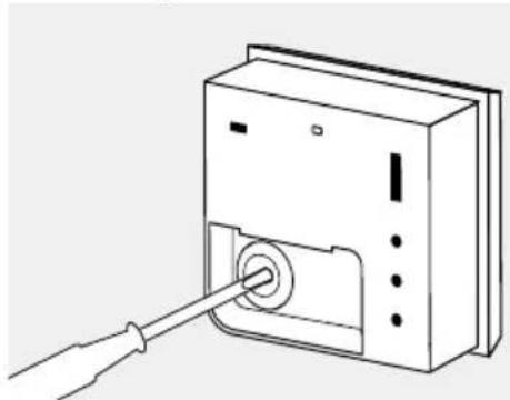
Line drawing of a device with a cable inserted into a slot (no text or symbols)Pierce through the middle of the rubber seal for the cable entry using a screwdriver.
| PORT DESCRIPTION | ||
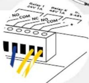
Relay 124 V, 1 A | NO = Normally openNC = Normally closedCOM | Bistable latching relay, max. 24 V DC/AC, 1 AThis port can be used to connect, for example, an electric door opener or a light control unit. The unit does not supply power to connected third-party devices (door opener, light control, etc.).The power supply for the third-party device must be installed separately (max. 24 V DC/AC, 1A). The switching time is set by the potentiometer “Time Relay 1”.Special safety feature: The relay retains its status even in the event of a power failure.The device is suitable for standalone operation without DoorBird components. The relay will only switch if a power supply is connected to the input. |
| Relay X48 V, 1 A | NO = Normally openCOM = Ground | MOSFET relay, max. 48 V DC/AC, 1 A.This connection can be used to connect, for example, an automatic door which requires a 1-second pulse. The power supply for the third-party device must be installed separately (max. 48 V DC/AC, 1 A). |
| Input5 - 48 V DC -/+ | (-) = negative pole(+) = positive pole | Power supply input, 5 - 48 V DC(e.g. DoorBird 15 V Power Supply - available separately)Alternatively: Connect DoorBird A1131 IP Video Mini Dome Camera |
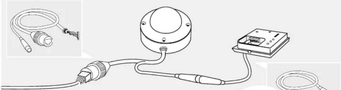
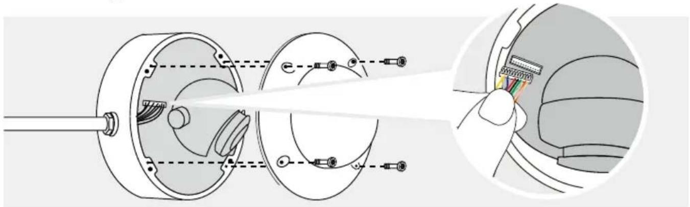
WHEN COUPLED WITH THE DOORBIRD A1131 IP VIDEO MINI DOME CAMERA
If the dome camera is already pre-installed in your home, you may need to replace the existing connected cable with the supplied cables.
natural_image
Technical illustration of a mechanical assembly with cross-sectional view and close-up detail (no text or symbols)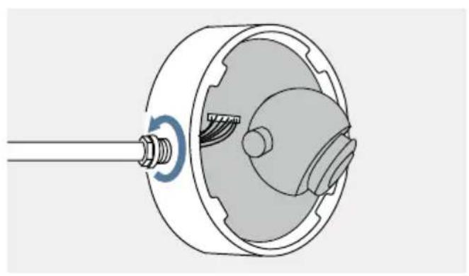
natural_image
Technical illustration of a mechanical component with a threaded shaft and internal gear assembly (no text or symbols)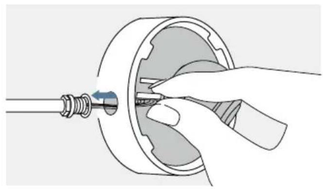
natural_image
Illustration of a hand inserting a small component into a mechanical housing (no text or symbols)
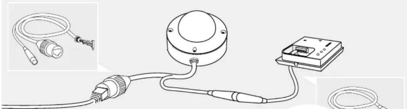
If you want to use the device as a motion detector for the DoorBird IP Video Mini Dome Camera, two cables are supplied for easy connection to the Mini Dome Camera. You can find a connection diagram for the white-yellow wire (type: M8 3P) below. There is no separate power supply required, the IP Video Mini Dome Camera powers the device.
natural_image
Diagram of a cable and connector assembly with a mounted device (no text or symbols present)| WIRE CONNECT TO PORT | ||
| Blue NO = Normally open Relay X > NO | ||
| Yellow Negative pole (-) Input 5 - 48 V DC - | ||
| Yellow-white striped | Positive pole (+) | Input 5 - 48 V DC + |
6
SETTINGS
| 1 | LEDOn Off | Switch to deactivate the Motion LED |
| 2 | Motion Detection | Switch to choose motion detection mode: |
| Off 1—Coming 2—Leaving 3—Coming/Leaving 4— | No motion detectionRecognise only distant motion eventsDetect only distant motion eventsDetect approaching and distant motion events | |
| 3 | LuxRotary control to set the day might switchover | |
| 4 | Time Relay 140 ms - 15 min - Rotary control to set the switching time of relay 115min | |
| 5 | SensitivityRotary control to set the sensitivity (distance) for the motion detection |
7
ACTIVATING THE DEVICE
Connect the device to the camera plug. You can tell whether the device is supplied with power by the Motion LED, which lights up when motion is detected. If the LED does not light up, please check that the LED is activated (LED switch on/off), detection mode is 2,3 or 4 and that the positive and negative poles of the device's power supply are connected correctly.
TECHNICAL DATA
GENERAL
| Material Polycarbonate | |
| Mounting type | Surface. Mounting brackets with two different angles included.Tripod thread DIN 4503-1 / ISO 1222 also supported. |
| Dimensions | 33 x 70 x 70 mm (L x W x H)1.30 x 2.75 x 2.75 in (L x W x H) |
| Power supply | 48 V DC. Power supply unit not included. |
| Power consumption | max. 1 W |
| Operating conditions | -25 to +55°C / -13 to 131°F Humidity 10 to 85 % RH (non-condensing) |
| Protection class IP65 | |
| Approvals CE, FCC, IC, RoHS, REACH, WEEE | |
| Scope of delivery | 1x 4D Security Radar Motion Sensor A80081x Installation manual2x Connection cable1x Wall mount adapter1x Small Parts |
| Connectors | • 1x Bistable latching relay, max.1 - 24 V DC/AC, 1 A, e.g. to trigger an an alarm or turn on a light• 1x Bistable latching relay, max.1 - 48 V DC/AC, 1 A, e.g. to trigger an an alarm or turn on a light• 5 - 57 V DC input (+,-) |
| Controls | • LED on/off• Motion detection direction (Off, Coming, Leaving, Coming/Leaving)• LUX intensity• Trigger duration time of Relay 1, up to 15 min• Sensitivity / Distance of the Radar, 1 to 10m / 3.3 ft to 33 ft |
| LED Motion Detection | |
| Weight | A8008: 67,5 gWall mount adapter: 10 g |
| EAN 4251489602148 | |
| Warranty see www.doorbird.com/warranty | |
| Garantie siehe www.doorbird.com/warranty | |
MOTION SENSOR
| Type Active | |
| Detection angle 54° (H), 70° (V) | |
| Range | 1 - 10 m (3.3 - 32.9 ft), depends on environment, configurable via rotary control. |
| Technology | 4D, Based on multiple integrated sensors and algorithms, e.g. Radio Frequency Energy (RFE) |
| Configuration | Via controls, e.g.· Range (1 - 10 m / 3.3 - 32.9 ft)· Movement direction (coming, leaving, both)· Day/night switchover |
INTEGRATED WIRELESS MODULES
Sensor 24 GHz, can be disabled
OPTIONAL ACCESSORIES
| Sold separately | Power supply unit (main adaptor) with 4 country-specific outlet adaptors |
It is possible that these manual still contains typographical errors or printing errors. The information in this manual will be checked regularly and corrections will be made in the next version. We accept no liability for errors of a technical or printing nature and their consequences.
LEGAL NOTES
General remarks
- DoorBird is a registered trademark of Bird Home Automation GmbH.
- Apple, the Apple logo, Mac, Mac OS, Macintosh, iPad, Multi-Touch, iOS, iPhone and iPod touch are trademarks of Apple Inc.
- Google, Android and Google Play are trademarks of Google, Inc.
- The Bluetooth® word mark and logos are registered trademarks of Bluetooth SIG, Inc.
- QR Code is a registered trademark of Denso Wave Incorporated in Japan and other countries.
- All other company and product names may be trademarks of the respective companies with which they are associated.
- We reserve the right to make changes to our products in the interests of technical advancement. The products shown may also look different from the products supplied based on ongoing enhancement.
- Reproducing or using texts, illustrations and photos from this instruction manual in any media - even if only in the form of excerpts - shall only be permitted with our express written consent.
- The design of this manual is subject to copyright protection. We do not accept any liability for any errors or any erroneous content or printing errors (even in the case of technical specifications or within graphics and technical sketches).
- Our products are in compliance with all technical guidelines, electrical and telecommunications regulations applicable in Germany, the EU and the USA.
- Our products and also the components contained therein (ICs, software, etc.) may only be used for civilian non-military purposes.
Data privacy and data security
- For maximum security, the device uses the same encryption technologies as are used in online banking. For your security, no port forwarding or DynDNS is used either.
- The data centre location for remote access over the Internet by means of an App is obligatory in the EU if the determined Internet IP-Address location of the device is within the EU. The data centre is operated in line with the most stringent security standards.
- Video, audio and any other surveillance methods can be regulated by laws that vary from country to country. Check the laws in your local region before installing and using this device for surveillance purposes.
If the device is a door-, indoor station or camera:
- In many countries video and voice signal may only be transmitted once a visitor has rung the bell (data privacy, configurable in the App).
- Please carry out the mounting in such a way that the detection range of the camera limits the device exclusively to the immediate entrance area.
- The device may come with a visitor history and motion sensor. You can activate/deactivate this function if required.
If necessary, indicate the presence of the device in a suitable place and in a suitable form.
Please observe any relevant country-specific statutory regulations concerning the use of surveillance components and surveillance cameras applicable at the installation site.
Check with the property owner and your house community if you are allowed to install and use this product. Bird Home Automation GmbH cannot be held responsible for any miss-use or miss-configuration of this product, including the unauthorized opening of a door.
Bird Home Automation cannot be held responsible for damages caused by improper existing installations or improper installation.
Software and operating system's updates (so-called "firmware updates") are generally automatically installed on the products of Bird Home Automation GmbH via Internet, if technically possible. Automatic firmware updates keep the products' software up to date so that they always work reliably, safely and efficiently. Through further development, features can be added, extended or slightly changed. Major changes or limitations to existing features will generally occur if Bird Home Automation GmbH deems it necessary (e.g. for data protection, data security or stability reasons, or to keep them up to date). When a firmware update is available, Bird Home
Automation GmbH's servers generally automatically distribute it to all compatible products connected to the Internet or Bird Home Automation GmbH's servers. This process is gradual and can take several weeks. As soon as a product receives a firmware update, the system will be installed and will restart by itself. Installed firmware updates cannot be undone. Since the products and software of Bird Home Automation GmbH are not explicitly customer-specific products, a customer cannot deny an automatic update if the product is connected to the Internet or to the Bird Home Automation GmbH's server.
Publisher
https://www.doorbird.com/downloads/warnings.pdf
KOMPONENTEN

Motion Sensor A8008
1x Installationsanleitung1x 4D Se
natural_image
Line drawing of two coiled electrical cables with connectors and a connector (no text or symbols)2x Anschlusskabel
1x Wandmontageadapter
GERÄT
Innen
natural_image
Simple line drawing of a rectangular box with a small square top and a small square base (no text or symbols)
VIDEOS
natural_image
Technical line drawing of a mechanical housing or enclosure with two screws inserted (no text or symbols)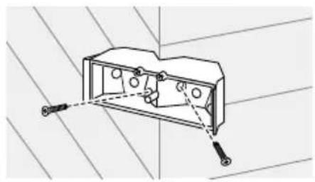
natural_image
Technical line drawing of an electrical outlet box with mounting holes and wiring (no text or symbols)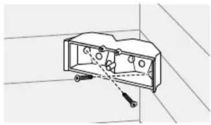
natural_image
Technical line drawing of a mechanical component with no visible text or symbolsnatural_image
Simple line drawing of a rectangular object with a curved arrow indicating rotation or movement, no text or symbols present.
natural_image
Diagram of a washing machine with a magnified inset showing the internal mechanism (no text or symbols present)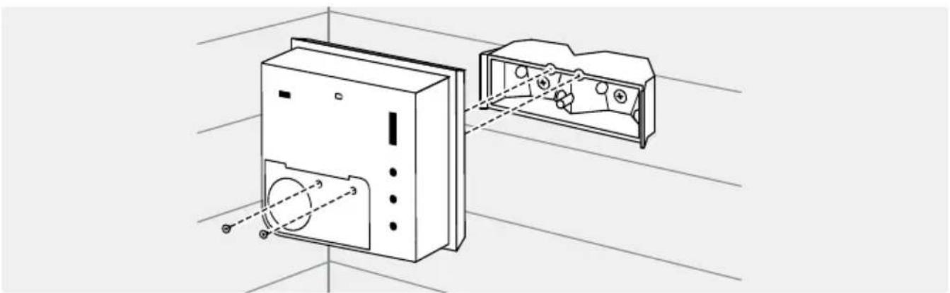
natural_image
Technical line drawing of a device with internal components and alignment lines (no text or symbols)natural_image
Line drawing of a mechanical device with a tool and circular component, no text or symbols present4
STROMVERSORGUNG
natural_image
Diagram of a device with a lever and curved arrow indicating motion (no text or symbols)natural_image
Line drawing of a device with a cable inserted into a slot (no text or symbols)natural_image
Technical illustration of a mechanical assembly with cross-sectional view and close-up detail (no text or symbols)DEUTSCH
natural_image
Technical illustration of a mechanical component with a shaft and housing (no text or symbols)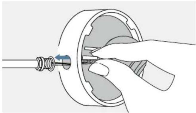
natural_image
Illustration of a hand inserting a small component into a mechanical housing (no text or symbols)
MANUEL D'INSTALLATION
This device meets the exemption from the routine evaluation limits in section 2.5 of RSS 102 and compliance with RSS 102 RF exposure, users can obtain Canadian information on RF exposure and compliance.
This equipment complies with Canada radiation exposure limits set forth for an uncontrolled environment.
https://www.doorbird.com/downloads/warnings.pdf
COMPOSANTS


natural_image
Line drawing of two types of electrical probes with coiled cables and connectors (no text or symbols)natural_image
Simple line drawing of a rectangular box with a small square top and a small square base (no text or symbols)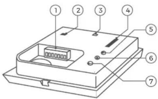

VIDÉOS
natural_image
Technical line drawing of a mechanical component with bolts and housing (no text or symbols)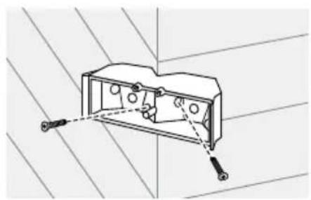
natural_image
Technical line drawing of an electrical outlet box with mounting holes and wiring (no text or symbols)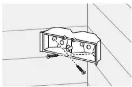
natural_image
Technical line drawing of an open electrical outlet with mounting hardware (no text or symbols)natural_image
Simple line drawing of a rectangular object with a curved arrow indicating rotation or movement (no text or symbols)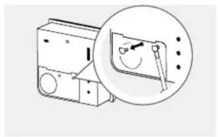
natural_image
Diagram of a device with an inset showing a magnified view of its internal components (no text or symbols present)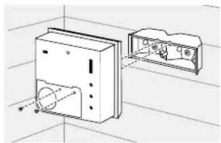
natural_image
Technical line drawing of a device housing with internal components and alignment lines (no text or symbols)OPTION 2
natural_image
Line drawing of a device with a bulb and circular components, no text or symbols present4
ALIMENTATION ÉLECTRIQUE
natural_image
Diagram of a device with a screwdriver inserted into a rectangular block, showing a curved arrow indicating rotation (no text or symbols present)natural_image
Line drawing of a computer case with a cable inserted into the case (no text or symbols)natural_image
Technical illustration of a mechanical assembly with cross-sectional view and close-up detail (no text or symbols)
natural_image
Two-step diagram showing mechanical assembly: one with a rotating shaft and internal components, the other with a hand holding a tool (no text or symbols)
natural_image
Diagram of a cable and connector assembly with a mounted device, shown in two views (no text or labels)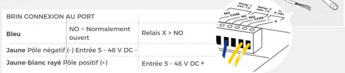
natural_image
Line drawing of two coiled electrical cables with connectors and a connector (no text or symbols)natural_image
Technical line drawing of an electrical enclosure with two screws and internal components (no text or symbols)
natural_image
Technical line drawing of a mechanical housing or enclosure with mounting holes and two screws, set against a diagonal grid background (no text or symbols)
natural_image
Technical line drawing of a mechanical component with no visible text or symbolsnatural_image
Simple line drawing of a rectangular object with a curved arrow indicating rotation or movement, no text or symbols present.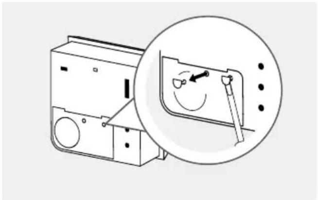
natural_image
Diagram of a washing machine with a magnified inset showing the internal mechanism (no text or symbols present)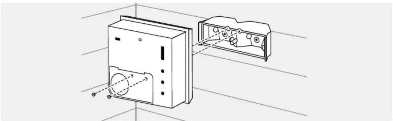
natural_image
Technical line drawing of a device with internal components and alignment lines (no text or symbols)natural_image
Line drawing of a mechanical device with a tool and circular component, no text or symbols present4
ALIMENTACIÓN
natural_image
Diagram of a device with a lever and curved arrow indicating motion (no text or symbols)natural_image
Line drawing of a device with a cable inserted into a slot (no text or symbols)natural_image
Technical illustration of a mechanical assembly with cross-sectional view and close-up detail (no text or symbols)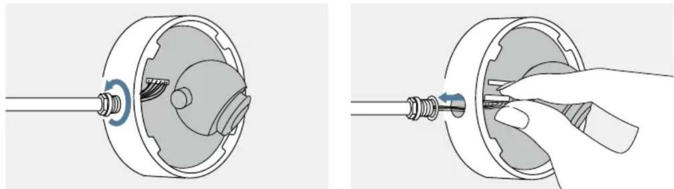
natural_image
Two-step diagram showing mechanical assembly: one with a rotating shaft and internal components, the other with a hand holding a tool (no text or symbols)
natural_image
Diagram of a cable and connector assembly with a mounted device, shown in two views (no text or labels)natural_image
Line drawing of two coiled electrical probes with connectors (no text or symbols)natural_image
Technical line drawing of a mechanical housing or enclosure with mounting holes and internal components (no text or symbols)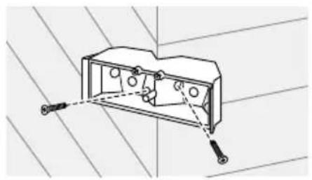
natural_image
Technical line drawing of a mechanical housing with mounting holes and a bolted joint (no text or symbols)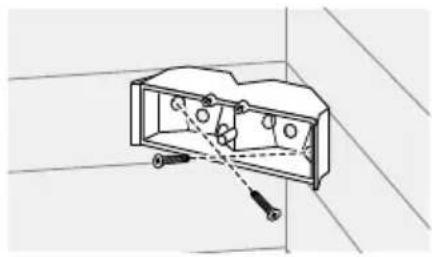
natural_image
Technical line drawing of a mechanical component with no visible text or symbolsnatural_image
Diagram of a device with a lever and curved arrow indicating rotation (no text or symbols)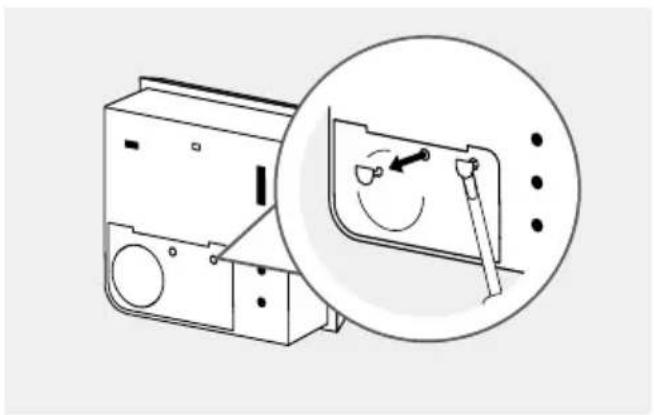
natural_image
Diagram of a washing machine with a magnified inset showing the internal mechanism (no text or symbols present)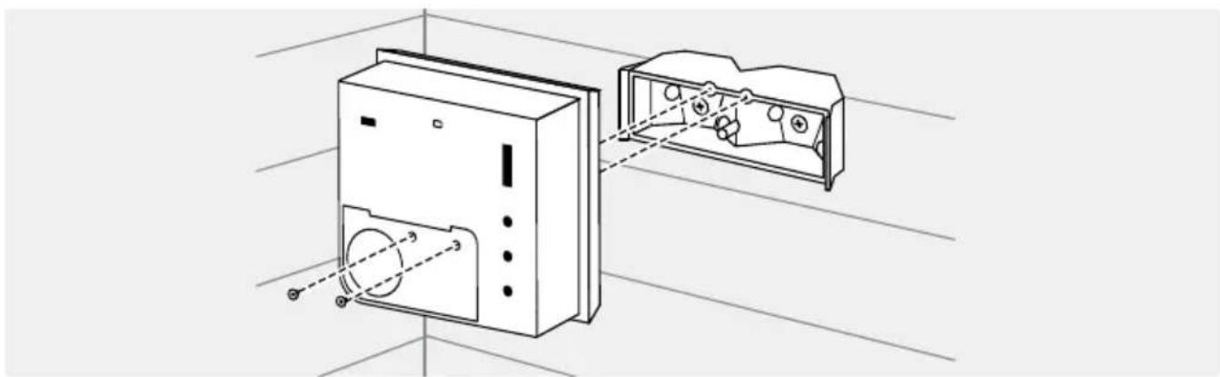
natural_image
Technical line drawing of a device with internal components and alignment lines (no text or symbols)OPZIONE 2
natural_image
Diagram of a device with a tool emitting a circular component, showing no text or symbols4
natural_image
Diagram of a device with a lever and curved arrow indicating motion (no text or symbols)natural_image
Line drawing of a device with a cable inserted into a slot (no text or symbols)natural_image
Technical illustration of a mechanical assembly with cross-sectional view and close-up detail (no text or symbols)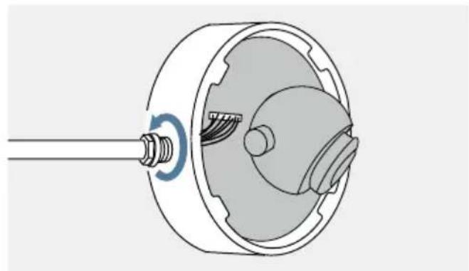
natural_image
Technical illustration of a mechanical component with a shaft and housing, showing internal structure without any text or symbols.
natural_image
Illustration of a hand inserting a plug into a mechanical component (no text or symbols)
natural_image
Line drawing of a flexible hose with connector and cable (no text or symbols)