Slim Pro - Cooker Airforce - Free user manual and instructions
Find the device manual for free Slim Pro Airforce in PDF.

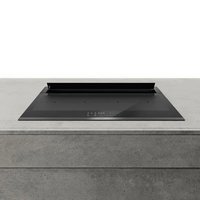
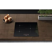
| Product type | Induction hob with integrated hood |
| Brand | Airforce |
| Model | Slim Pro |
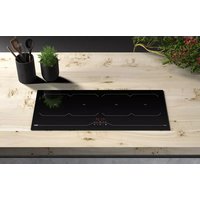
| Number of cooking zones | 5 (4 oval + 1 rectangular) |
| Dimensions of oval zones | 210 x 190 mm (2.1 kW, boost 3.0 kW each) |
| Dimensions of rectangular zone | 210 x 390 mm (3.7 kW) |
| Maximum total power | 7400 W (adjustable from 1000 to 7400 W) |
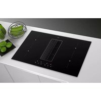
| Extraction type | Extraction or filtration (recirculation) |
| Number of extraction speeds | 9 levels + Boost |
| Extraction Boost function | Yes, 6 min max in extraction, unlimited in filtration |
| Recovery tank capacity | 0.7 L |
| Filtration system | Metallic grease filters + regenerable TWIN odor filters |
| Filter saturation indication | Yes (30 h for grease, 120 h for odors) |
| Special cooking functions | Bridge, Chef Cook, Automatic rapid heating, Keep warm |
| Timer | Independent per zone, up to 1h59 min, alarm function |
| Child safety | Yes, with control lock |
| Automatic safety shut-off | Yes, depending on cooking level (from 10 min at Boost to 522 min at level 1) |
| Pause mode | Yes, up to 10 minutes |
| Power management system | Yes, power distribution between zones |
| Pan recognition | Automatic, detection and shut-off in absence of pan |
| Residual heat indicator | Yes, H symbol on screen |
| Maintenance mode | Opens the extraction flap without motor for access to filters |
| Electrical supply | 220-240 V ~ 50/60 Hz (estimated) |
| Recommended cleaning | Damp cloth and mild product; glass scraper for stubborn residues |
Frequently Asked Questions - Slim Pro Airforce
User questions about Slim Pro Airforce
0 question about this device. Answer the ones you know or ask your own.
Ask a new question about this device
Download the instructions for your Cooker in PDF format for free! Find your manual Slim Pro - Airforce and take your electronic device back in hand. On this page are published all the documents necessary for the use of your device. Slim Pro by Airforce.
USER MANUAL Slim Pro Airforce
INNOVA
Slim Pro
| D | MONTAGE- UND GEBRAUCHSANWEISUNG |
| GB | INSTRUCTIONS ON MOUNTING AND USE |
| F | PRESCRIPTIONS DE MONTAGE ET MODE D'EMPLOI |
| NL | MONTAGEVOORSCHRIFTEN EN GEBRUIKSAANWIIZING |
| ES | MONTAJE Y MODO DE EMPLEO |
| I | ISTRUZIONI DI MONTAGGIO E D'USO |

natural_image
Illustration of two gloves with textured soles (no text or symbols)IT Per tutte le operazioni di installazione e manutenzione utilizzare guanti da lavoro
EN Always wear work gloves for all installation and maintenance operations
DE Bei allen Installations- und Instandhaltungsarbeiten immer Schutzhandschuhe tragen.
FR Munissez-vous de gants de travail avant d'effectuer toute opération d'installation et d'entretien.
NL Draag bij alle installatie- en onderhoudswerkzaamheden werkhandschoenen.
ES Todas las operaciones de instalación y mantenimiento se deben realizar utilizando guantes de trabajo.
PT Para todas as operações de instalação e manutenção, utilize luvas adequadas para este tipo de atividade
GR Πάντοτε να φοράτε γάντια εργασίας για όλες τις επεμβάσεις εγκατάστασης και συντήρησης.
SV Använd alltid skyddshandskar vid installation och underhåll.
FI Käytä asennus- ja huoltotöissä suojakäsineitä.
NO Ved alle installasjonsprosedyrer og alt vedlikehold av ventilatoren må man bruke arbeidshansker
DA Ved alle installations- og vedligeholdelsesindgreb skal der bæres arbejdshandsker.
PL Wszelkie czynności montażowe i konserwacyjne wykonywać w rękawicach ochronnych.
CZ Při všech instalačních a údržbových pracích používejte pracovní rukavice
SK Pri všetkých inštalačných a údržbárskych prácach používajte ochranné pracovné rukavice.
HU Valamennyi üzembe helyezési és karbantartási müvelethez használjon védőkesztyűt
BG за всички операции по инсталиране и техническо обслужване използвайте работни ръкавици.
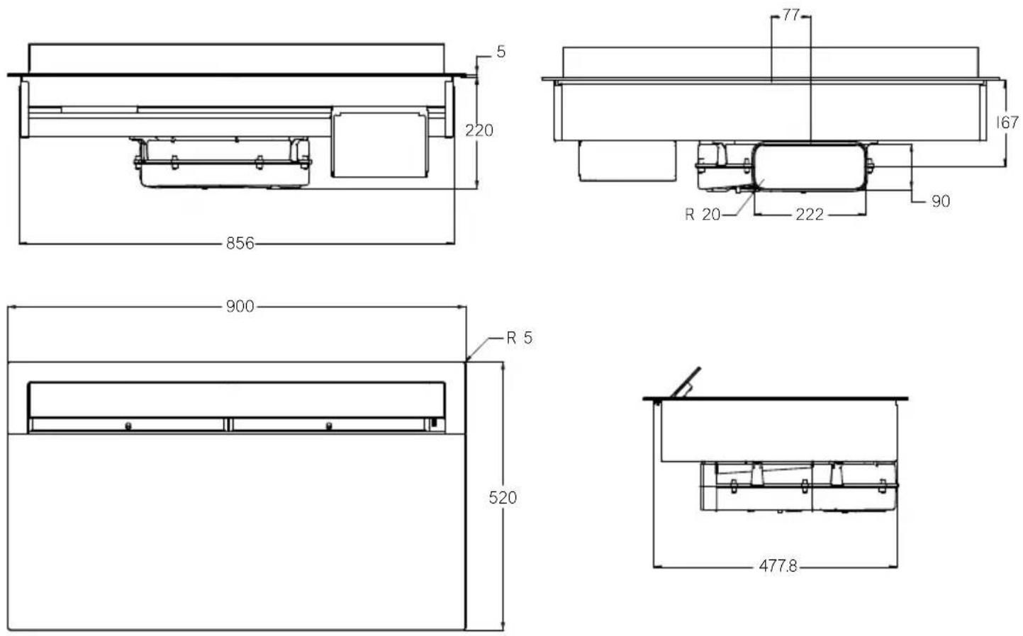
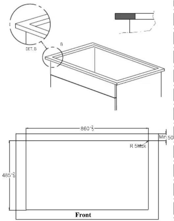
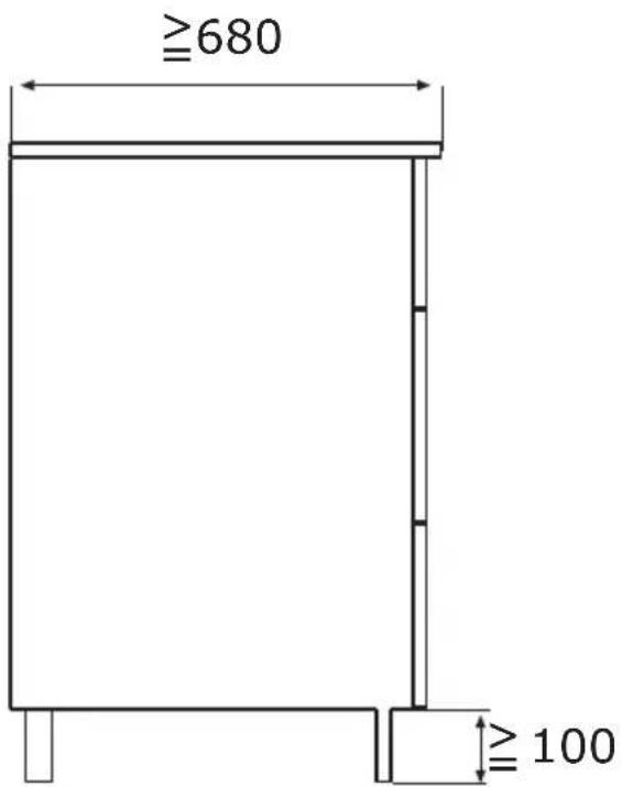
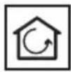
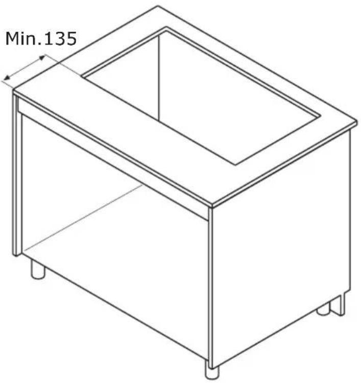
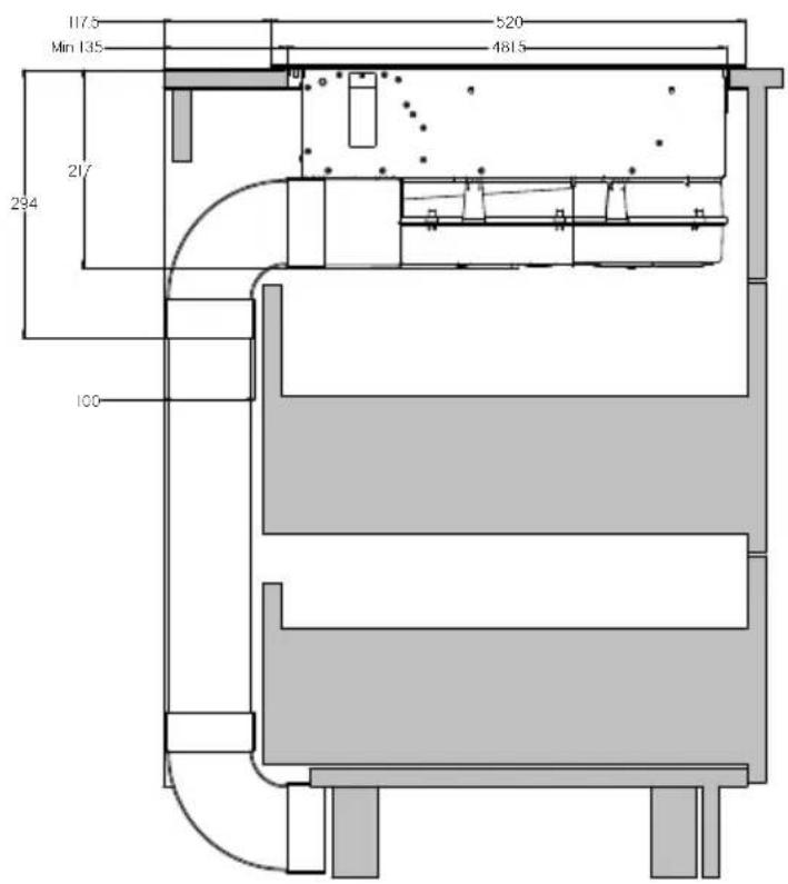
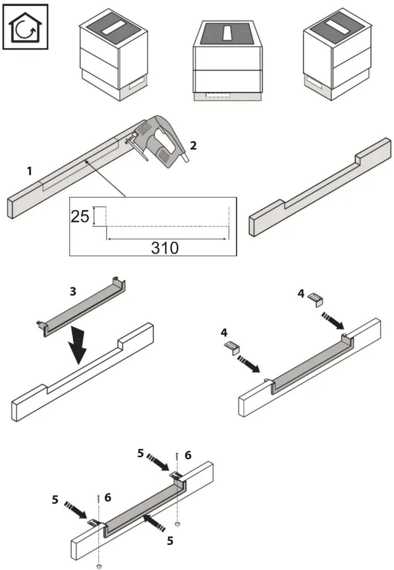
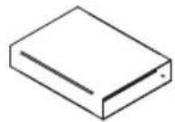
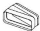
CUT OUT Innova Slim
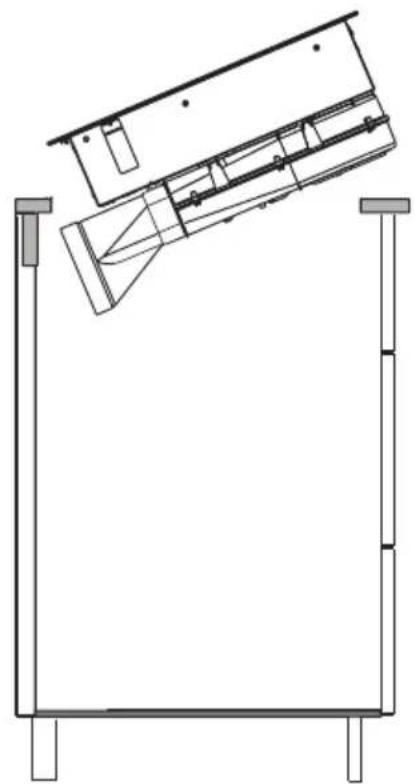
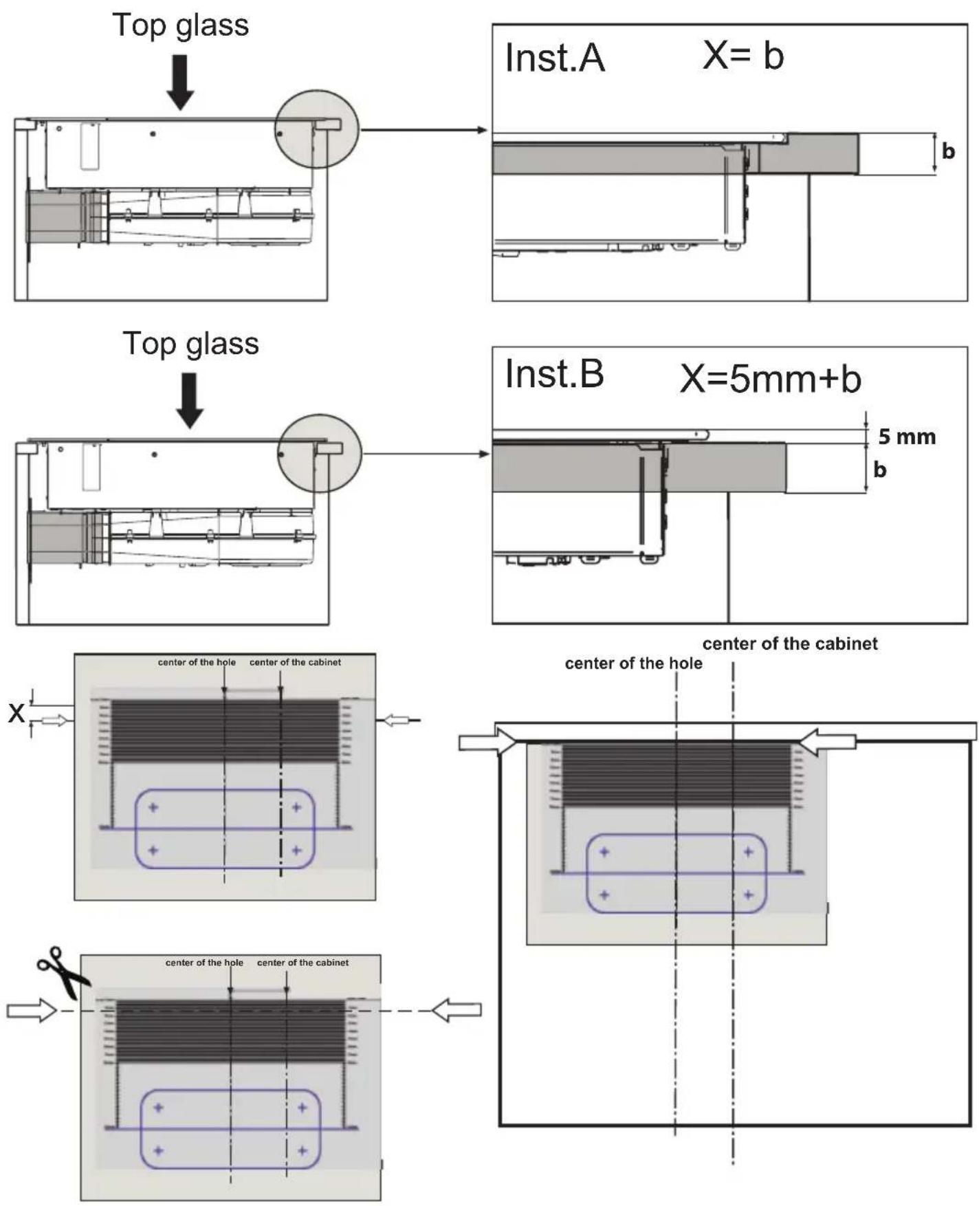
Standard installation Flush top installation
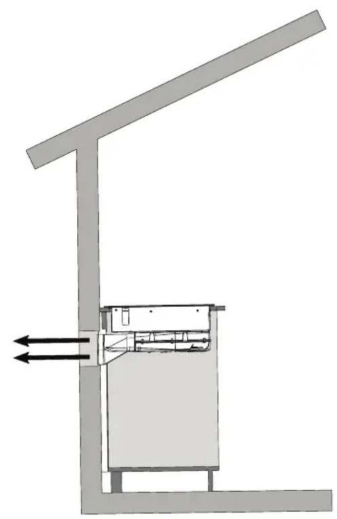
natural_image
Architectural cross-section diagram of a building structure with directional arrows indicating airflow or movement (no text or symbols)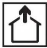
natural_image
Technical line drawing of a mechanical assembly with support legs and internal components (no text or symbols)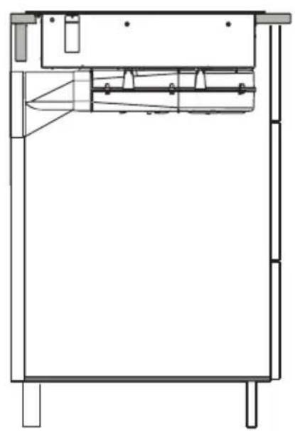
natural_image
Technical line drawing of a mechanical assembly or enclosure with internal components and mounting feet (no text or symbols)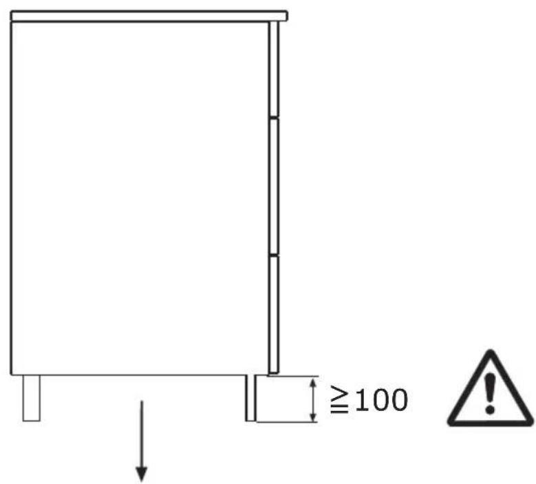
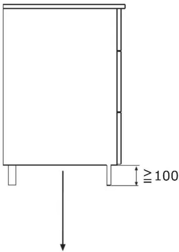
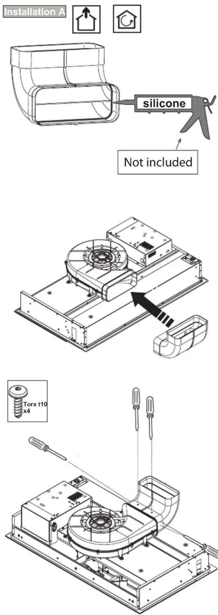
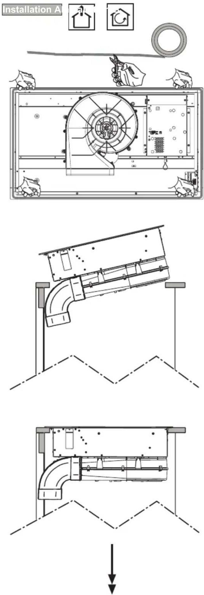
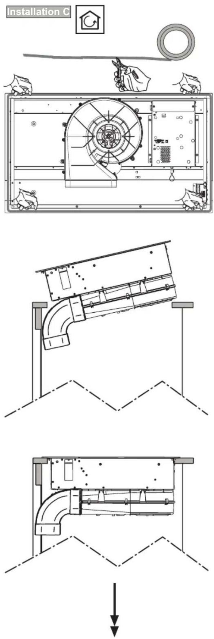
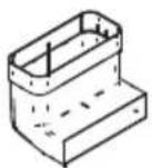
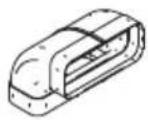
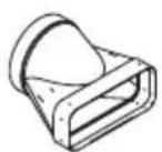
Installation A
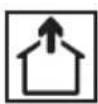

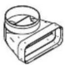
Installation B

natural_image
Isometric line drawing of a rectangular metal enclosure with a recessed top and side legs (no text or symbols)


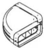
Installation B


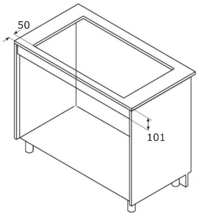
natural_image
Simple black vertical arrow pointing downward (no text or symbols)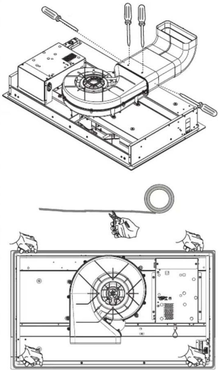
natural_image
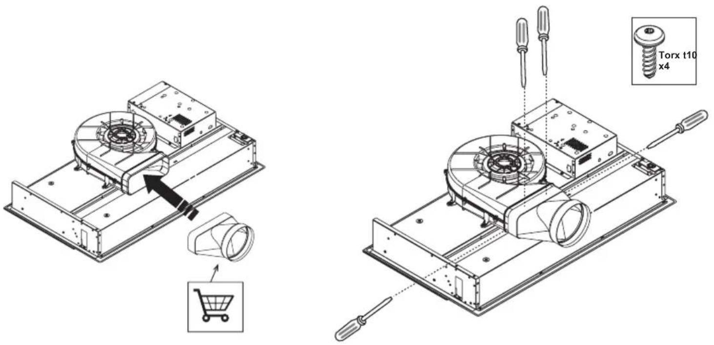
Technical line drawing of a mechanical assembly with exploded and assembled views (no text or symbols)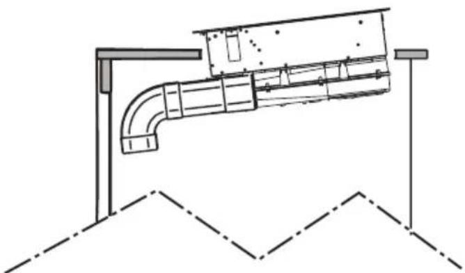
natural_image
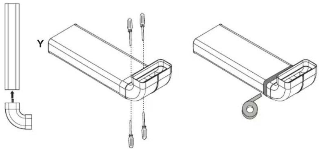
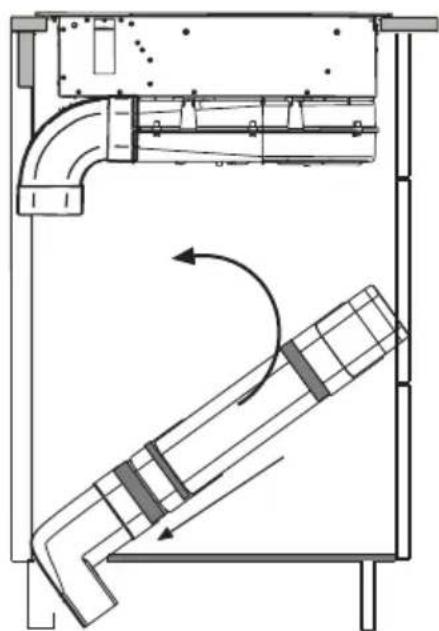
Technical line drawing of a pipe assembly with support structures (no text or symbols)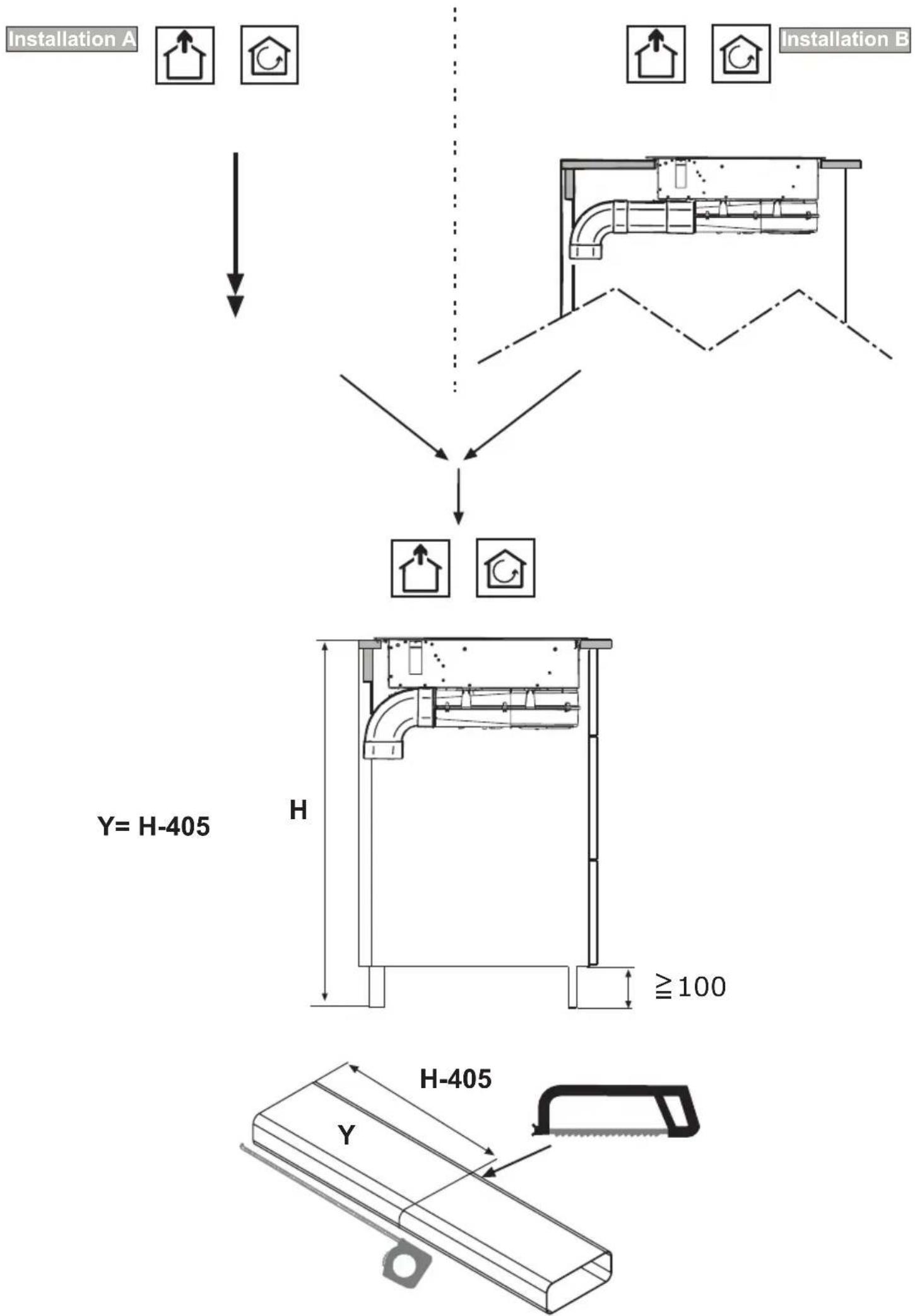
natural_image
Technical line drawings of a mechanical bracket assembly with tool pins and mounting features (no text or symbols)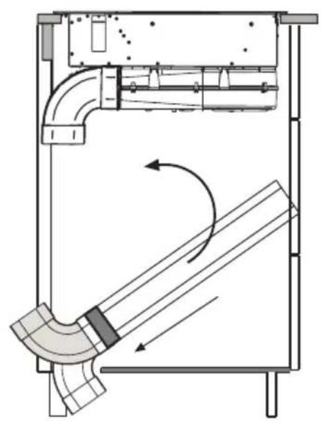
natural_image
Technical diagram of a mechanical assembly with curved pipes and a rotating shaft (no text or symbols)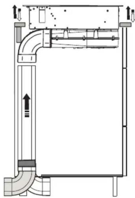
natural_image
Technical diagram of a mechanical ventilation system with pipes and ducts (no text or labels)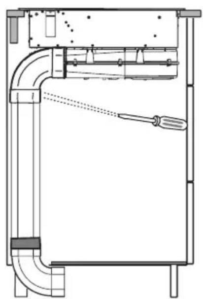
natural_image
Technical line drawing of a mechanical assembly with pipe connections and a screwdriver (no text or symbols)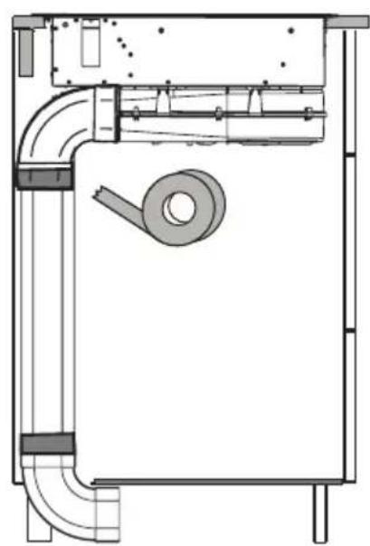
natural_image
Technical line drawing of a mechanical or electrical enclosure with pipes and a central component (no text or symbols)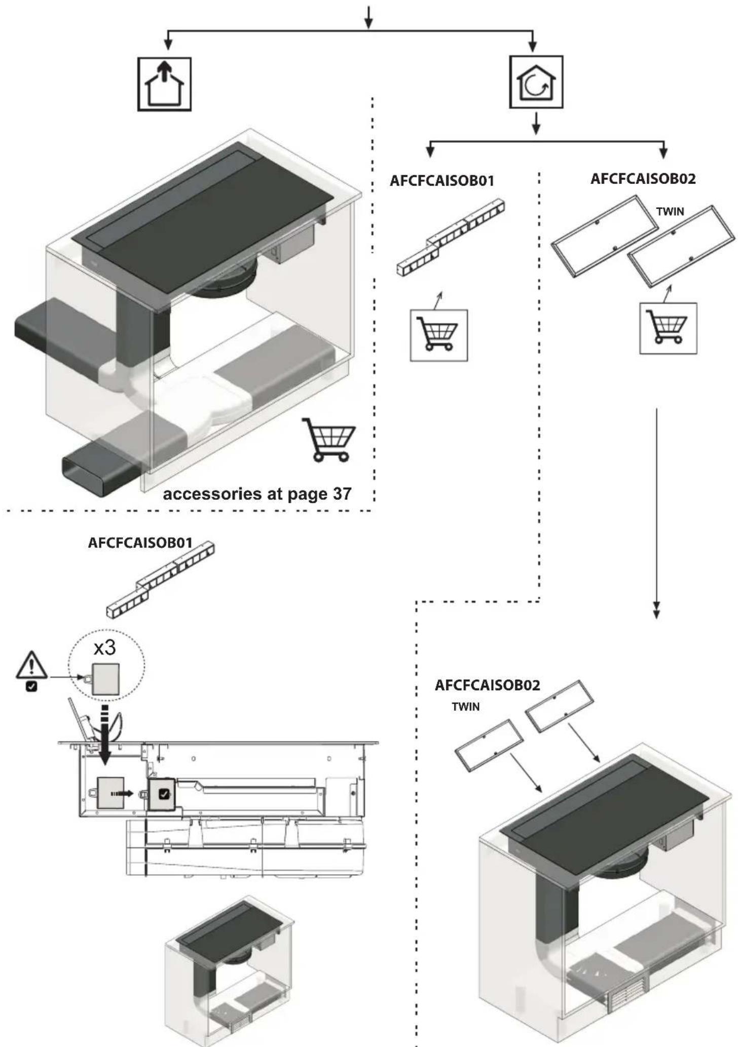
X=13 Z=230
X=16 Z=250
accessories at page 37

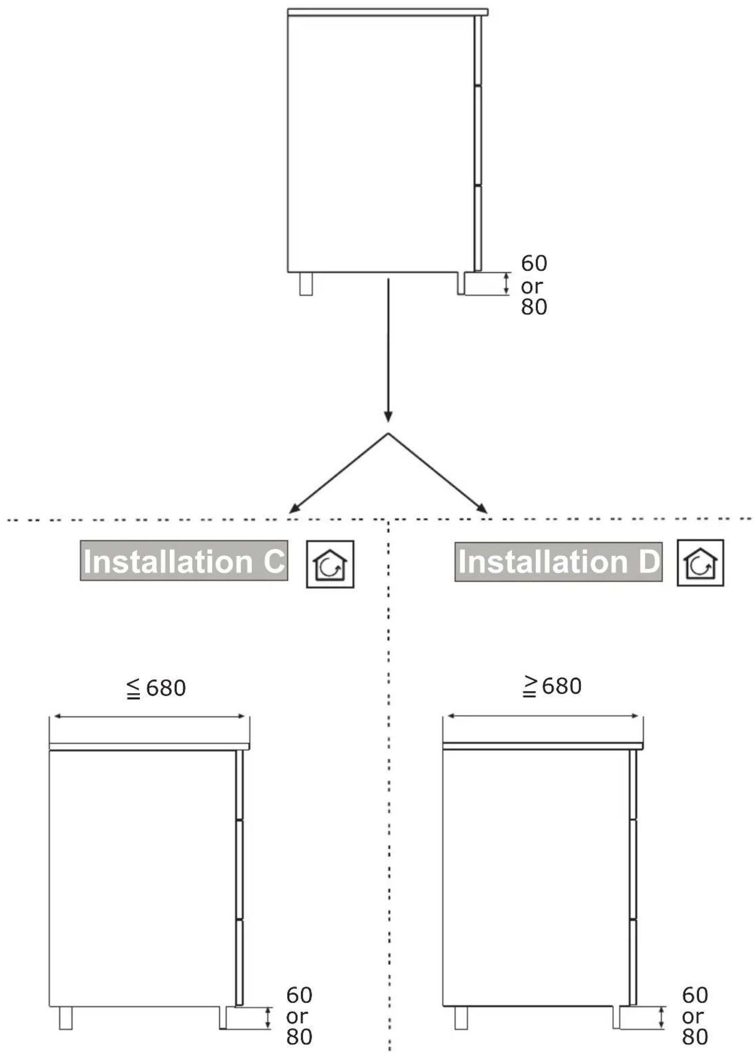
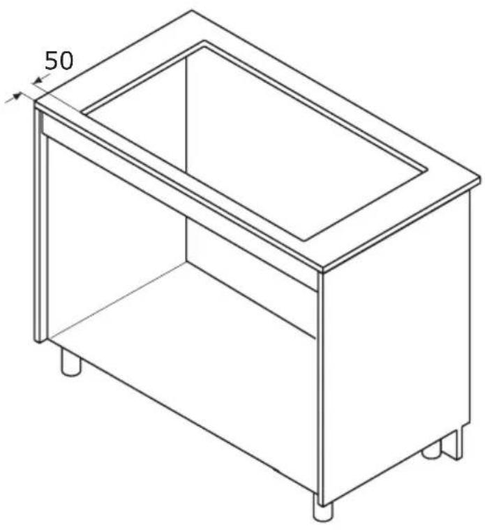
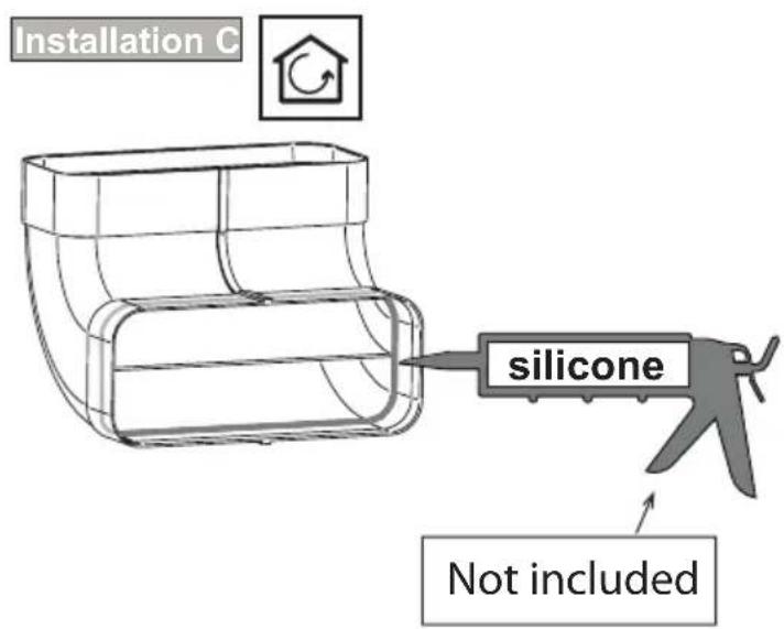
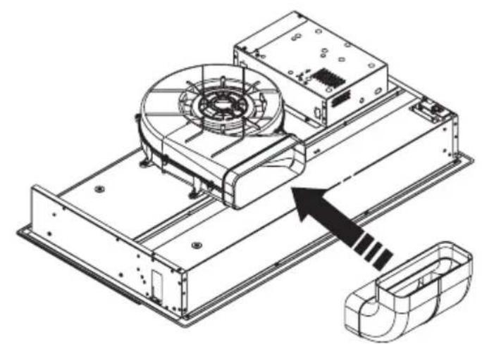
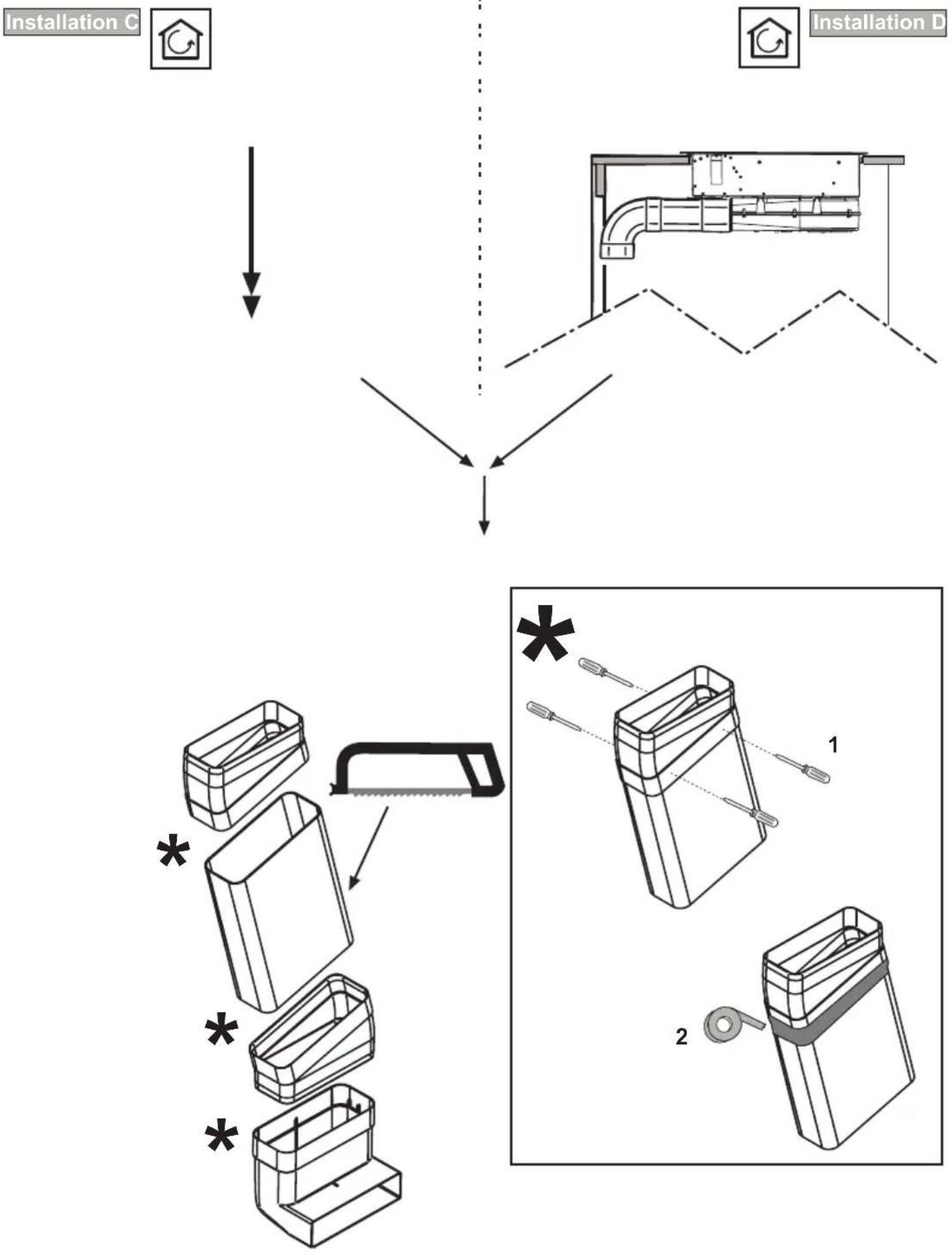
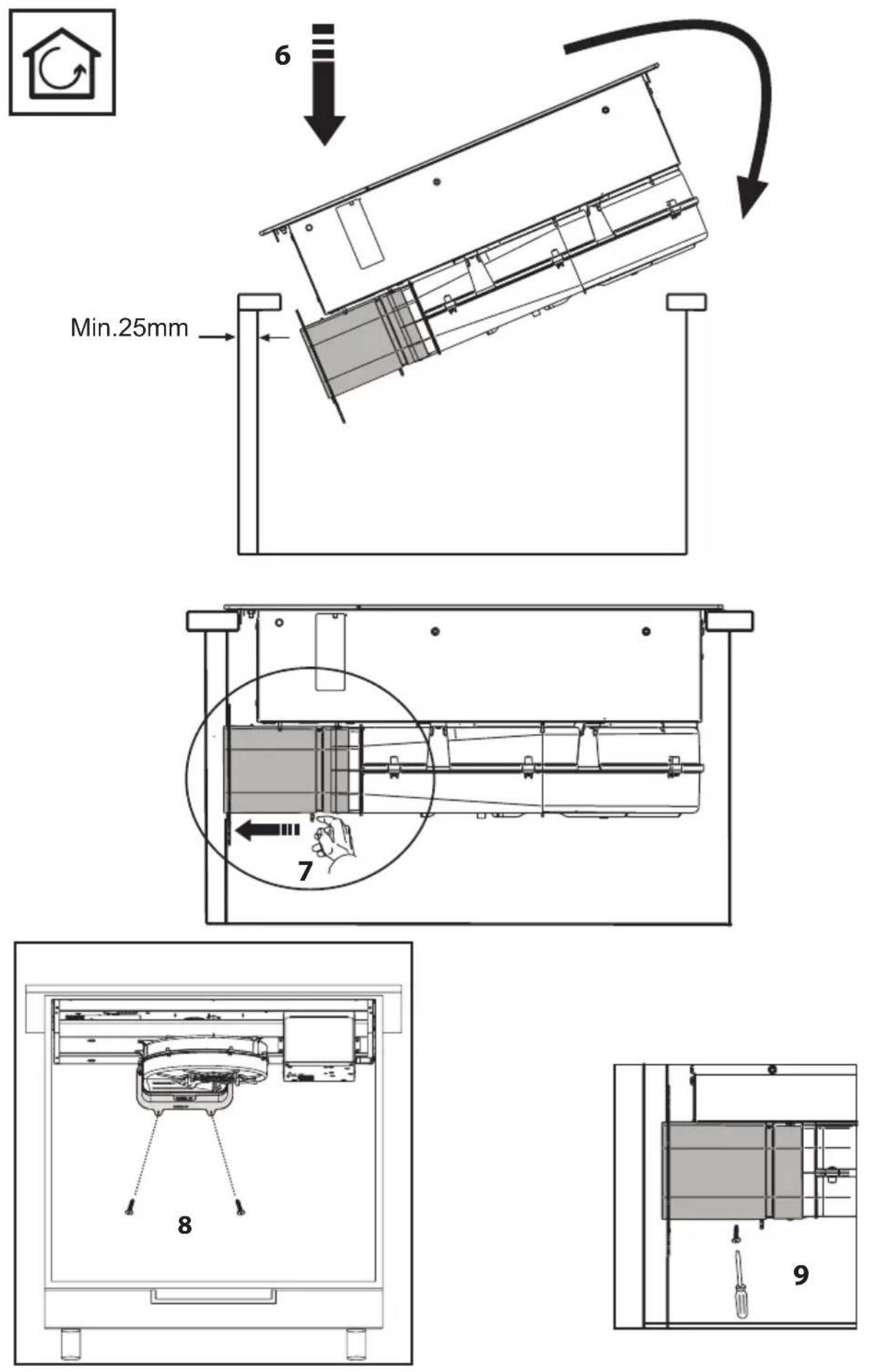
Installation C

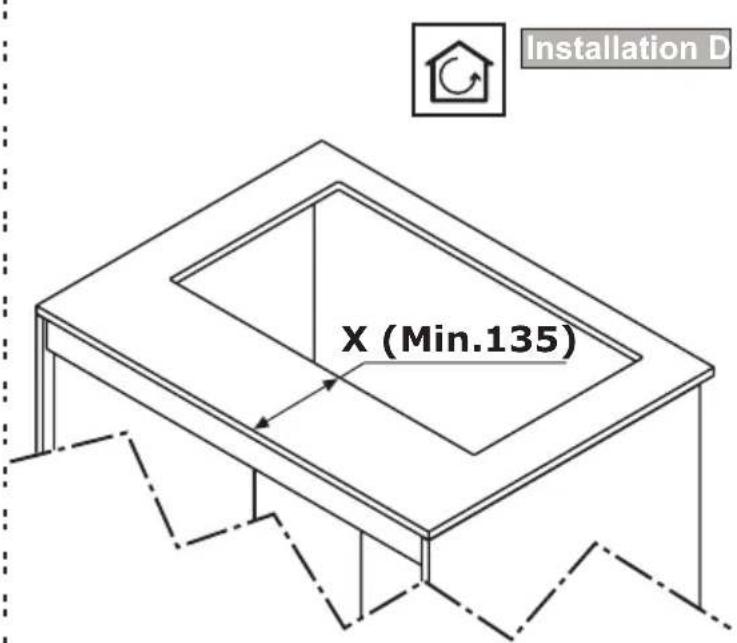
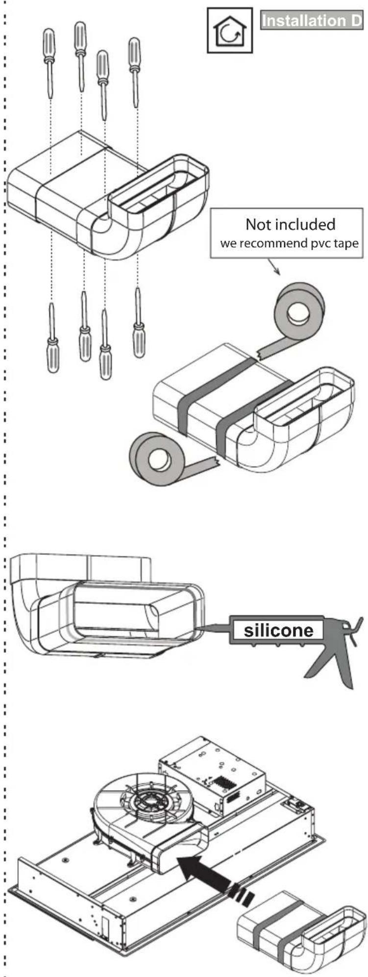
Installation D
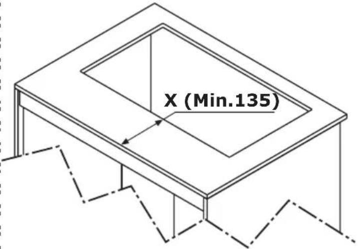
natural_image
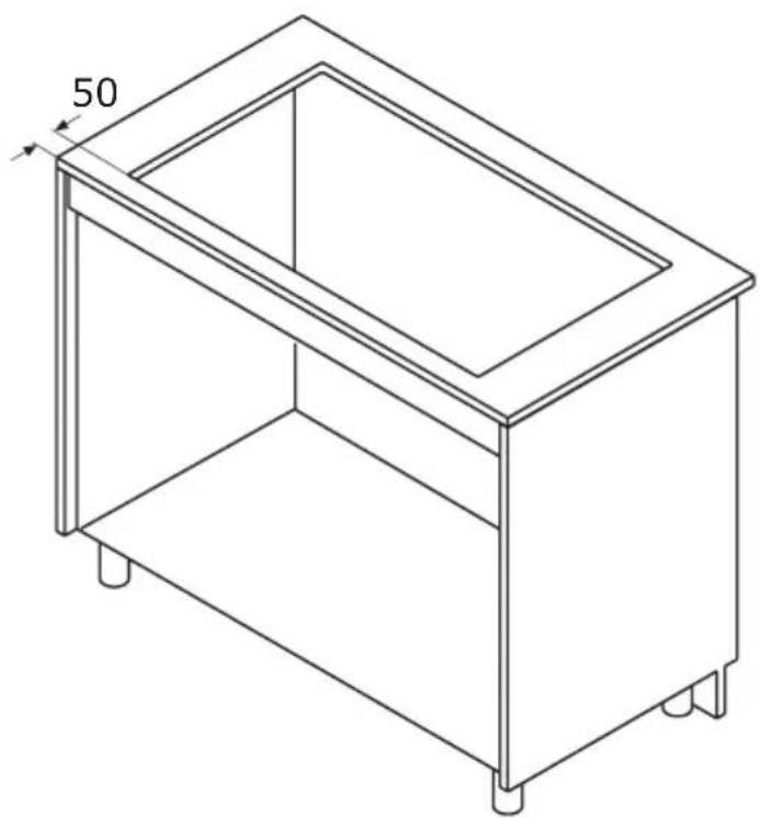
Isometric line drawing of a rectangular metal frame with four legs and a central opening, labeled '50' at the top (no text or symbols on the diagram itself)
natural_image
Technical line drawing of a mechanical assembly with a fan and housing, showing internal components and an arrow indicating direction (no text or symbols present)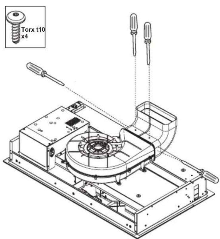


natural_image
Simple black downward arrow on white background (no text or symbols)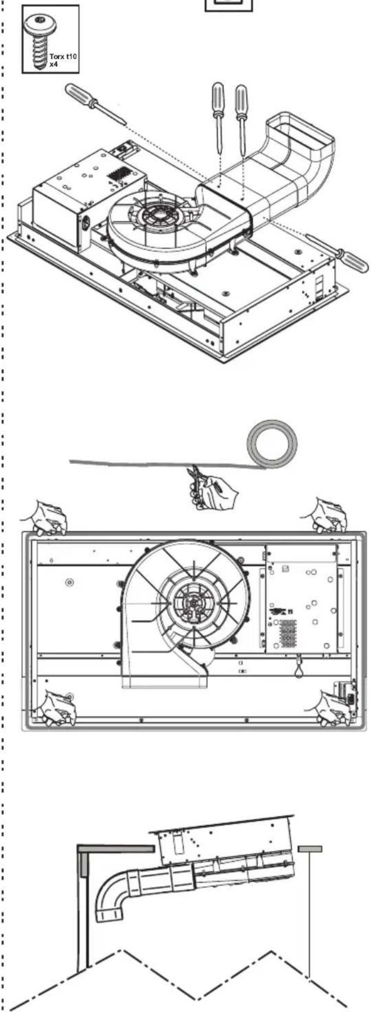

natural_image
Technical diagram of a mechanical or electrical component with directional arrows indicating motion (no text or symbols present)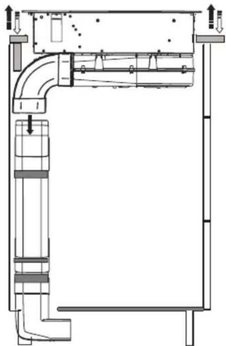
natural_image
Technical schematic of a mechanical or electrical assembly with pipes and structural elements (no text or labels)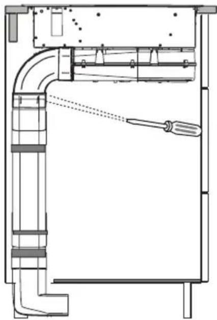
natural_image
Technical line drawing of a mechanical assembly with pipes and a screwdriver (no text or symbols)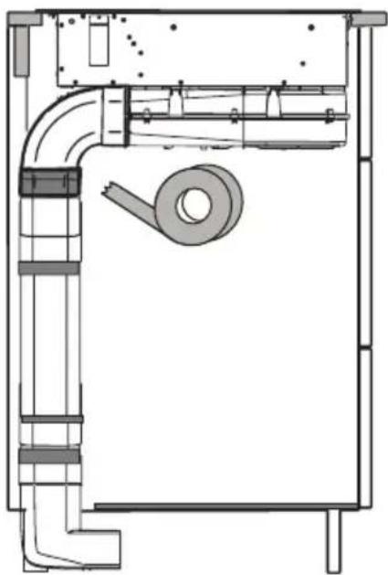
natural_image
Technical line drawing of a mechanical or electrical component with no visible text, numbers, or symbols.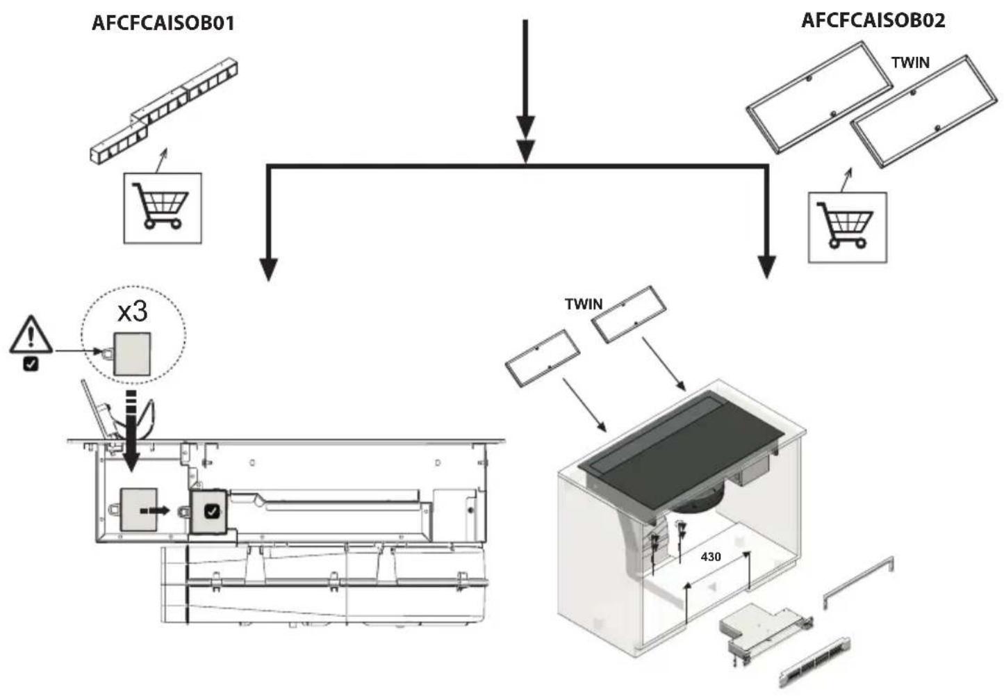
flowchart
graph TD
    A["AFCFCAISOB01"] --> B["Shopping Cart"]
    C["AFCFCAISOB02"] --> D["TWIN"]
    B --> E["Display Module"]
    D --> E
    E --> F["Output Display"]
    G["x3"] --> H["Display Module"]
    I["TWIN"] --> J["Display Module"]
    J --> K["430 System"]
natural_image
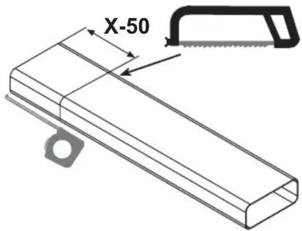
Simple diagram showing a tool and a right-pointing arrow next to an 'X' symbol (no text or labels)
flowchart
graph TD
    A["Component"] --> B{Direction}
    B --> C["Arrow to Left"]
    C --> D["Arrow to Right"]
    D --> E["Section 3"]
    E --> F["Arrow to Right"]
    F --> G["Arrow to Left"]
    G --> H["Arrow to Right"]
natural_image
Technical line drawing of an electronic device with a component labeled '3' and an arrow indicating assembly (no text or symbols beyond label)
natural_image
Technical line drawing of a mechanical device with internal components and external assembly (no text or symbols)D
- It is recommended to check and empty the water collector every two weeks.
- Remove the filters and dry the inside of the water collector with a dry cloth.
F
Récupérateur d'eau
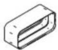
natural_image
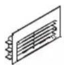
Simple line drawing of a rectangular block with horizontal lines, no text or symbols present.AFC4043005
AFC4021003
AFCRAC0120994
AFC4043004 (90°)
AFC4043003 (90°)
AFC4043007 (15°)
AFC4043006 AFC4043002
KRASP003
KRFH6
natural_image
Technical line drawing of a mechanical component with two views: one showing a flat housing and the other a side panel (no text or symbols)AFCFCAISOB01
natural_image
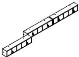
Isometric line drawing of a structural beam with multiple supports (no text or symbols)AFCFCAISOB02
natural_image
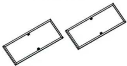
Two identical rectangular frames with evenly spaced dots, no text or symbols present
D
Once installation is complete, verify the correct functioning of the product, then wait 24 hours to allow the silicone to dry completely.
F
This instruction handbook is conserved together with the Innova Slim for future consultation. If the equipment is sold or transferred to another person, make certain the instruction handbook is supplied together with it, so that the new user can become aware of the operation of the cooker hood and related warnings. These warnings have been compiled for your safety and the safety of others. Please take the time to read them carefully before installing and using the equipment. Be sure to also consult the drawings in the front pages, including the alphabetic and numeric references in the text descriptions. Closely follow the instructions in this manual. The manufacturer declines all responsibility for any inconveniences, damage or fires caused due to non-compliance with the instructions in this manual. The installation and electrical connection must be provided by a qualified service technician. The supplier is not liable for any warranty for damages caused by improper installation or improper use of the appliance. Do not modify or seek to modify the specifications of this appliance.
The cooking top must always be used within the limits of normal domestic use, not for professional use, but simply to prepare and keep dishes warm. Any other use is not allowed. The unit should not be left unsupervised during its operation.
This appliance can be used by children from the age of 8 onwards, and by persons with reduced physical, sensory or mental capabilities, or lack of experience and knowledge, provided they are properly monitored, or if they have been instructed in the safe use of the appliance and are aware of related dangers.
Children must not be allowed to play with the appliance.
Make use of the locking device to prevent children from accidentally turning on the device, or modifying its functions. The unit should not be left unsupervised during its operation.
Do not control the cooking top using a remote timer.
The unit should not be left unsupervised during its operation.
Make certain children at home are prevented from toppling hot pots and pans to the floor. Turn the handles and knobs of pots and pans to the side on the cooking top, so that they are above the cooking top, and to prevent the risk of burns.
For safety reasons, the cooking top must be used only after having been installed in its recessed housing.
Prior to proceeding with the installation, check to make sure there are no visible signs of damage to the cooking top. Never start up a damaged unit, as it may pose a safety risk.
Cleaning and maintenance must not be carried out by children without proper supervision.
If the power cord is damaged, it must be replaced by a qualified service centre or technician only.
CAUTION: The hob protection devices must be only those designed by the appliance manufacturer or those indicated as suitable in the manufacturers instructions or the hob protection devices incorporated in the appliance.
The use of inappropriate protection devices may provoke accidents.
During the installation the equipment must be connected to a power source whose system impedance is matched to a value of 0.005+j0.005[Ohm].
Do not seal the area between the glass and the worktop with silicone because should the cooktop need to be replaced, the glass could break during removal.
The unit's installation and electrical connection to the power grid must be carried out by qualified service technicians only. The device's electrical safety can be guaranteed solely if a regular ground connection is provided for the cooking top. If in doubt, have the electrical system checked by a qualified electrician. Do not connect the cooking top to the mains using extension cords or multiple sockets, since they will not guarantee the required safety (e.g. risk of overheating).
Prior to connecting the cooktop, compare the connection specifications (voltage and fre quency) indicated on the unit's identification nameplate with those of the mains electricity supply.
These specifications must absolutely correspond, otherwise the unit may be subject to damage. Contact an electrician if in doubt.
D isconnect the unit from the mains when carrying out installation work, maintenance or repairs.
Comply with all air discharge regulations.
CAUTION: If the surface is cracked, switch off the appliance to avoid the possibility of electric shock.
Never open unit's outer casing. Any contact with live parts or the modification of electrical or mechanical parts can cause operating abnormalities.
The induction hob should not be used as a work surface. The rough underside of food containers can scratch the surface of the cooktop.
Always keep the cooking areas and underside of food containers perfectly dry.
Fire hazard
Oil and grease that are too hot will catch fire quickly.
Do not leave overheated oil or grease unsupervised.
If oil or grease should catch fire, do not attempt to put out the flames with water. Extinguish the flames with a lid or plate, or with a fireproof blanket. Turn off the cooking zone. Never place flammable items on the hob.
WARNING: Fire hazard: do not leave objects on the cooking surface.
Burn hazard
CAUTION: This appliance and its accessible parts become very hot during use.
Pay attention to avoid touching the heating elements.
Keep children under 8 years of age away from the appliance, unless they are continually monitored.
Do not place objects such as knives, forks, spoons or lids on the induction top, as they may overheat.
Do not heat closed containers, such as tin receptacles, on the cooking top. The excess pressure generated could blow up the container.
Suitable food containers
Only ferromagnetic containers are suitable for induction cooking; the following receptacles, in particular, are suitable: enamelled steel, cast iron, special dishes for induction cooking in stainless steel.
Use only pots and pans with a smooth bottom. Do not introduce any objects between the bottom of the pot and the glass ceramic surface, such as adapters.
| Cooking zone Minimum diameter | |
| OCTA (single) 110 mm | |
| OCTA (bridged mode) | 230 mm |
To find whether receptacles are suitable, check whether they are attracted by a magnet.
Another type of special receptacle exists for induction cooking, with a bottom that is not entirely ferromagnetic.
Non-suitable food containers
Never use recipients made of: normal finegrained steel, glass, pottery, copper and aluminium. Do not place empty containers on the cooking zone, as they may cause damage.
Do not place hot recipients on the control panel, in the area of the pilot lights or on the edge of the cooking top, as they may cause damage.
Danger of mishaps
Pots from which liquids have completely evaporated can cause damage to the glass ceramic top, for which the manufacturer does not assume any responsibility.
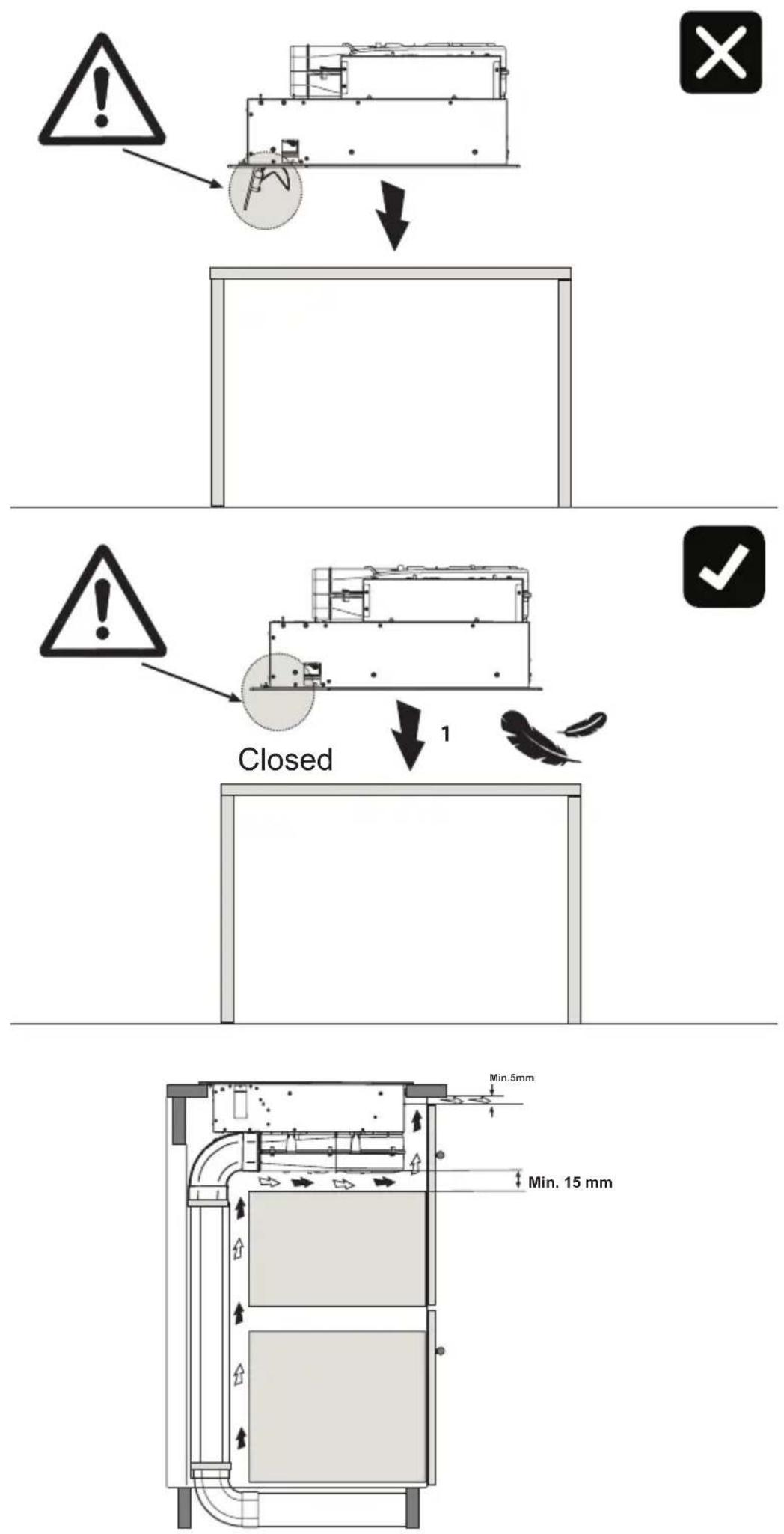
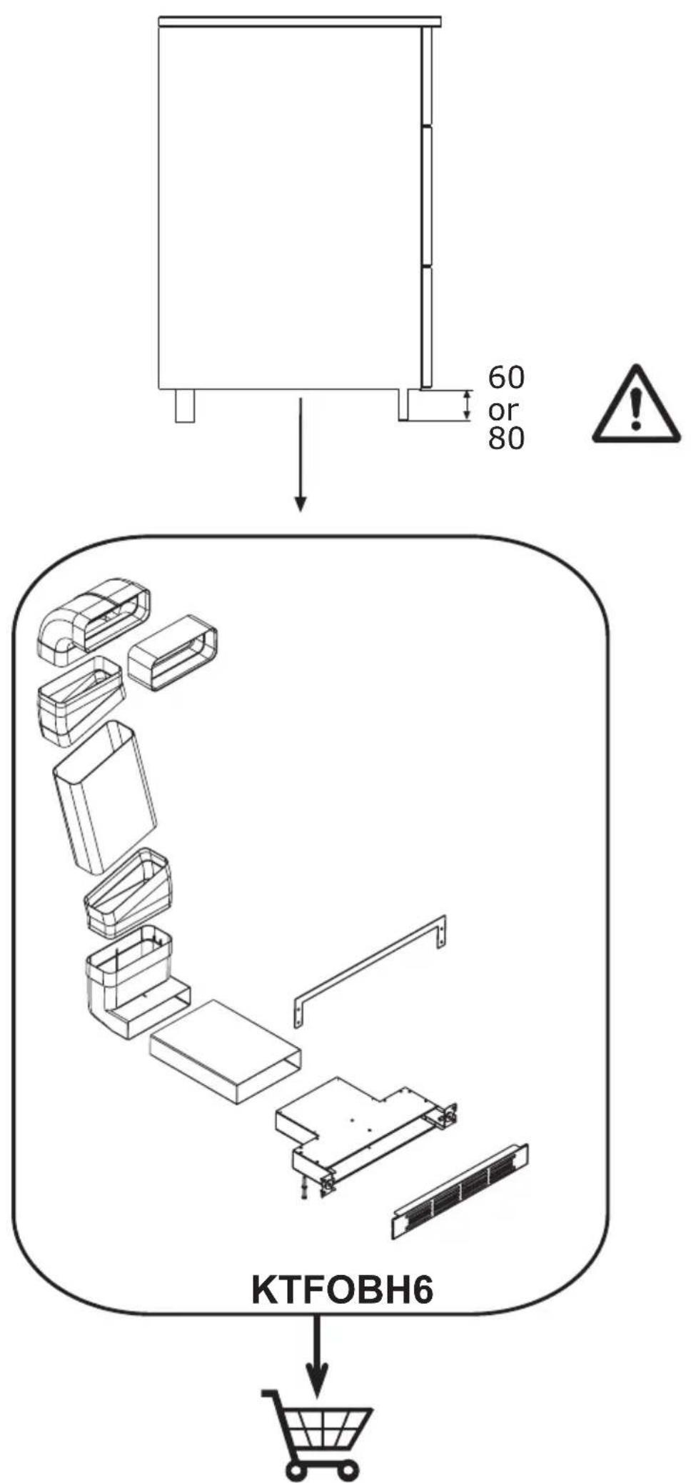
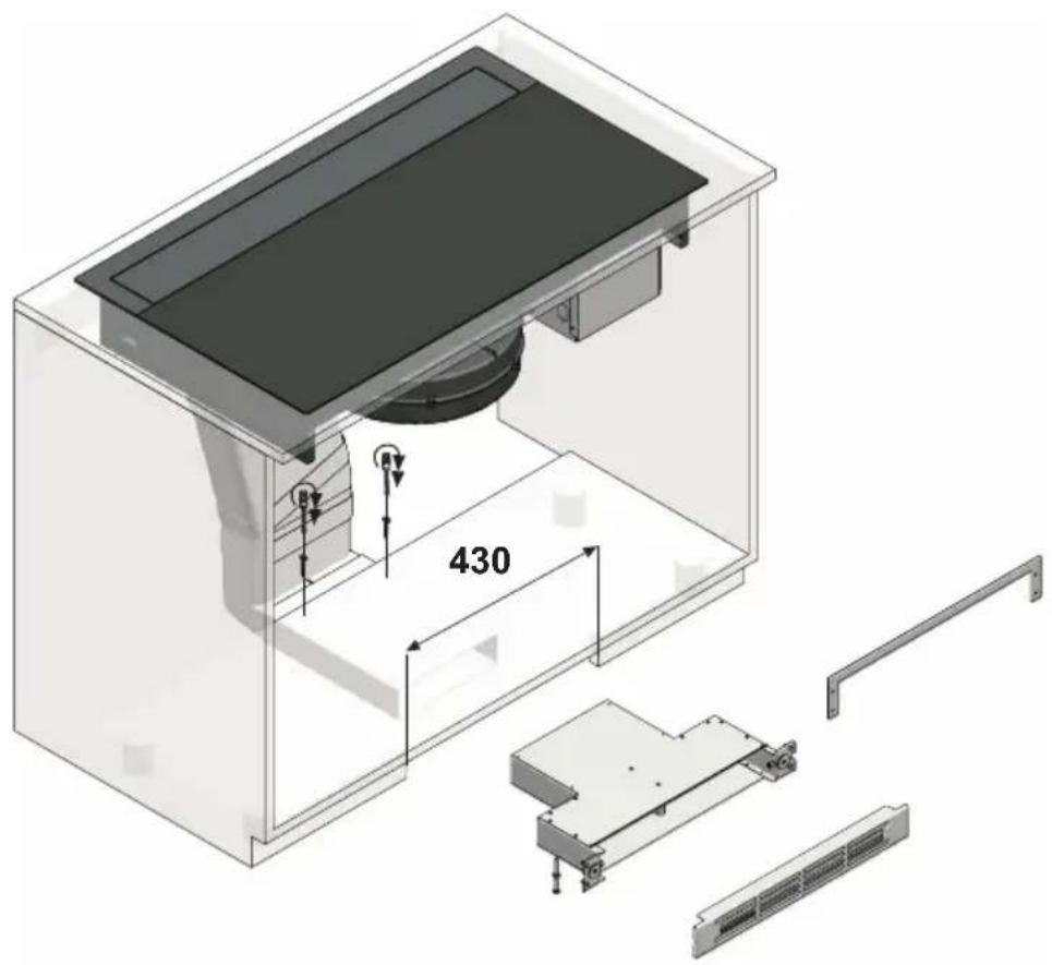
The appliance is equipped with a cooling fan. If a drawer is set under the recessed hob, a suitable distance must be ensured between the contents of the drawer and the lower part of the unit, in order to avoid compromising ventilation.
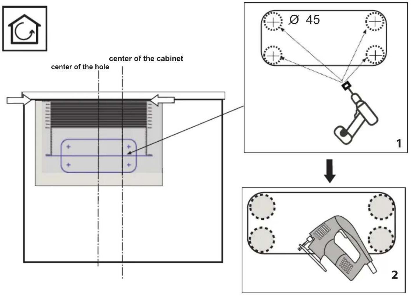
The worktop should be flat and horizontal. The furniture should be cut to measure before installing the appliance. Remove any chips to avoid compromising the operation of electrical components.
Do not store small objects or sheets of paper in the drawer under the cooking hob, since such objects may be aspirated and could break the fan, thus hindering the unit's cooling; likewise, do not store metal or inflammable objects, which could become very hot or catch fire.
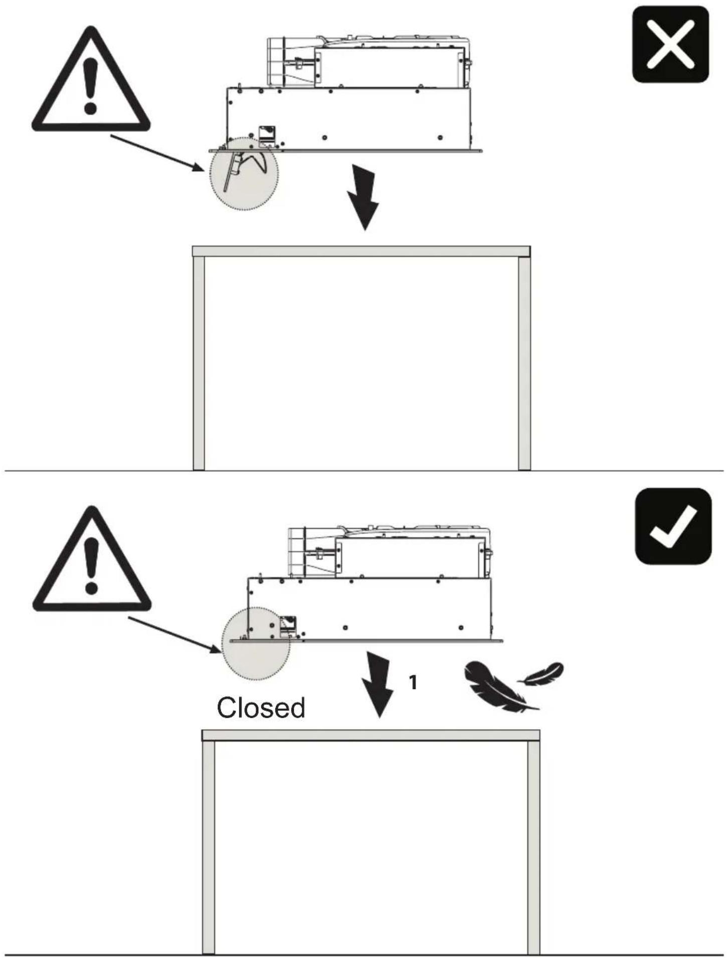
If the cooking hob is assembled behind a cabinet door, power it on only with the door left open. Close the cabinet door only if the appliance and residual heat indicator lights are off.
If the unit is assembled above an oven or an electric pyrolytic stovetop, it should not be operated while the pyrolytic process is ongoing, as it can trigger the cooktop's overheating protection.
The cooktop should not be installed above dishwashers because the steam released by the latter may lead to faulty operation of the electronic circuit of the cooktop.
Do not make use of any steam devices, as steam can reach the appliance's live parts and cause a short circuit.
Any interventions or repairs on the unit during the warranty period must be carried out solely by the manufacturer's authorised service centre; conversely, the warranty will be is invalidated and terminated immediately. The manufacturer will not recognise any warranties under any circumstances for any problems subsequently encountered.
Replace any defective or damaged parts with original spare parts: only original spare parts can ensure compliance with safety standards.
Notice to persons with pacemakers: keep in mind that an electromagnetic field is generated in the immediate vicinity of the unit while it is in operation.
The possibility that the pacemaker's operation may be affected is very remote. If in doubt, contact the pacemaker manufacturer or your doctor.
Warning: do not pour any type of liquid into the suction slot of the hood.
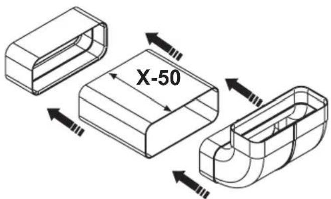
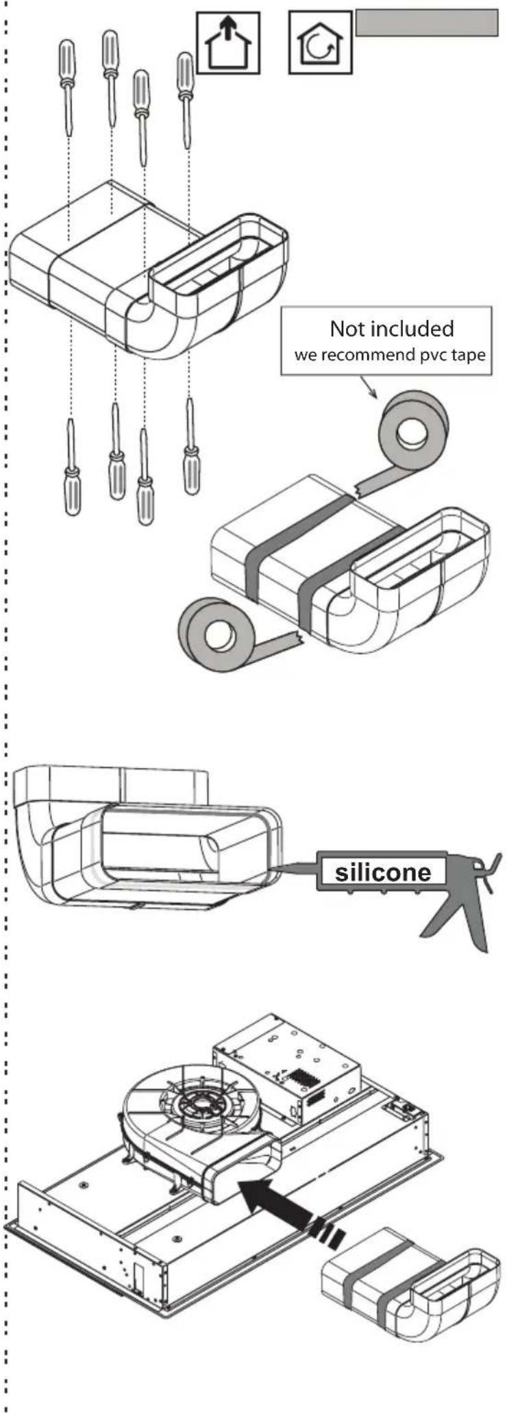
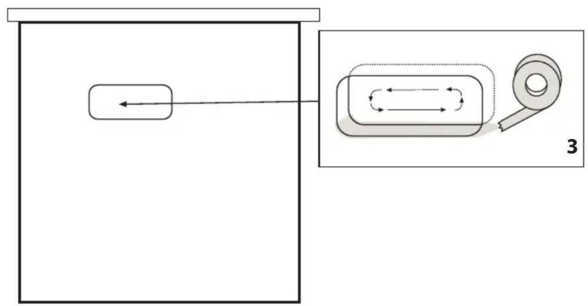
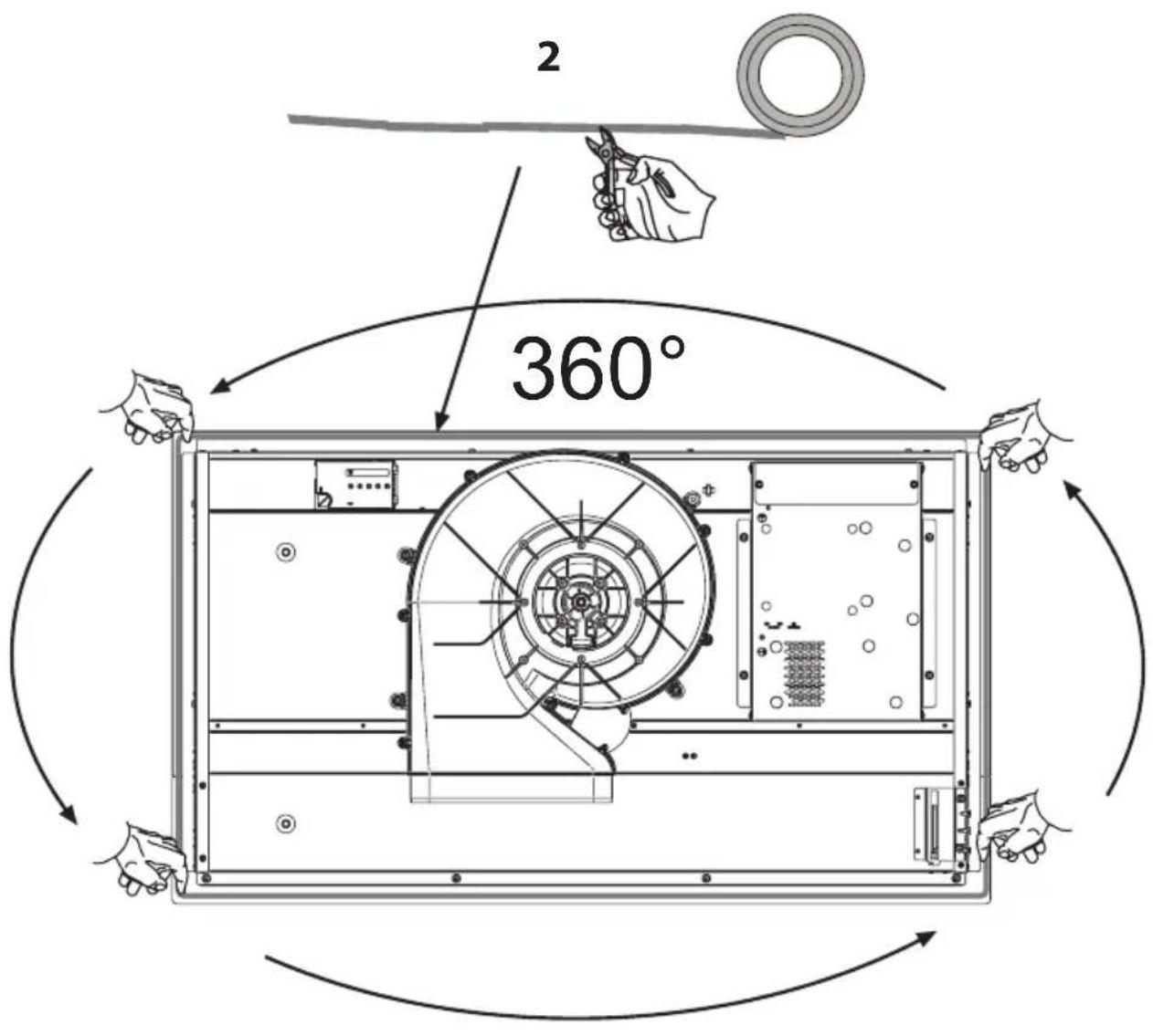
Warning: it is recommended to seal with silicone or adhesive tape all the joints of the pipes, both of the exhaust pipes and the fittings that join the various parts.
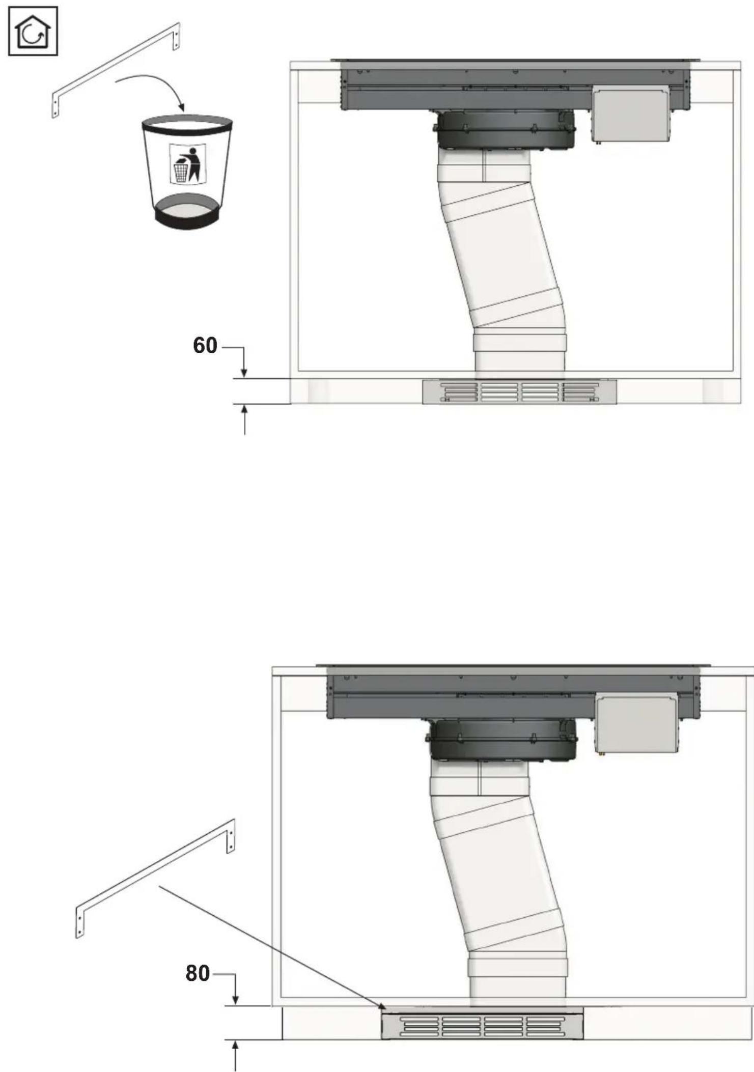
In the case of installation in filtration mode, pay particular attention to the positioning of the fume exhaust area to avoid possible turbulence, so as not to interfere either with the suction system or with the hob.
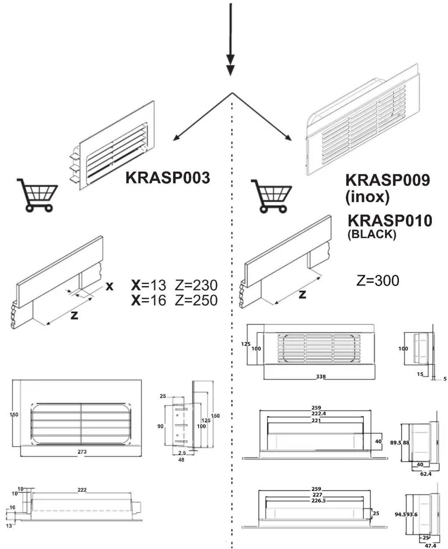
In the installations in filtration mode, place the pipes inside of the plinth of the furniture, ensuring air evacuation to the outside via a special grid, in order to prevent moisture from building up inside of the same.
The liquid collection tray must be emptied on a regular basis.
Such tray is designed to contain about 0,7 litre of water; in case of spillage or fall of fluids on the device, turn off the appliance immediately and empty the tray. If the liquid fallen on the floor is greater than the maximum capacity of the tray, turn off the device and contact the customer service immediately.
After use, turn off the cooking hob through its control device and do not rely on the cookware detector.
Noise emissions
Induction can generate slight noise emissions, which can vary depending on the material, type of pot and power setting selected.
When the cooktop is used frequently, the cooling fan turns itself on to protect the electronics, generating a buzzing sound: this is perfectly normal.
First usage
Use a damp cloth to clean and dry the cooktop before using it for the first time. It is recommended to dry the appliance after having cleaned it with a damp cloth, in order to prevent the build-up of limescale.
When the unit is powered on for the first time, odours or fumes may be generated. The odour will diminish with each subsequent use, until it disappears altogether. Odours and any fumes are not caused by a faulty connection or damage to the appliance, and are not hazardous to health.
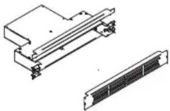
YOUR INDUCTION HOB
Description
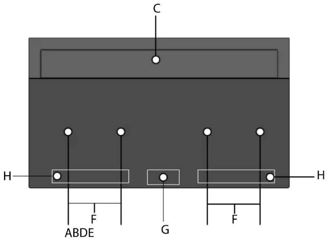
A. Cooking zone 210 x 190 mm / 2,1 kW (boost 3,0 kW)
B. Cooking zone 210 x 190 mm / 2,1 kW (boost 3,0 kW)
C. Extractor
D. Cooking zone 210 x 190 mm / 2,1 kW (boost 3,0 kW)
E. Cooking zone 210 x 190 mm / 2,1 kW (boost 3,0 kW)
F. Connected cooking zones 21 x 39 cm / 3.7 kW
G. Control panel
H. Control panel hod
OPERATION
Cooking zones function principle
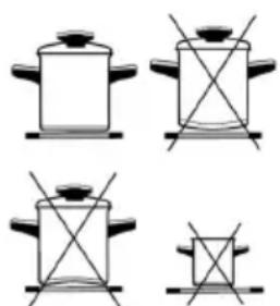
Appropriate cookware
natural_image
Four identical line drawings of cooking pots with handles and crosshairs, no text or symbols presentThe hob is fitted with high power induction hotplates. Heat is generated directly at the bottom of the dish, where it is most needed, without any losses through the glass surface. The glass surface is not heated directly, but only by return heat transmitted by the dish. This heat figures as H after the hotplate is turned off.
The induction hotplate generates heat from the induction coil, installed underneath the glass surface. The coil creates magnetic field at the bottom of the dish (which can be magnetized) which in turn originates whirling flows of current which then heat.
- Induction hotplate will function perfectly only if appropriate pot is used.
- The pot should be in the middle of the hotplate during cooking.
- The appropriate pot is the one which enables induction, for example steel, enamel or steel alloy. Pots made from steel alloy with copper or aluminium bottom, or glass pots are inappropriate.
- If you use the pressure pot, keep it under close surveillance until proper pressure is obtained. Hotplate should first operate on maximum power, then follow the manufacturer's instructions.
When buying cookware, check if it bears the label "allows induction".
Note:
When Bridge function is selected, you can use the created zone in different ways, with one or two pots.
If you use larger pots than the recommended maximum size, the heating time will be longer, because the heating will propagate from center to edges of the pot by conduction, in this case also the temperature will be very inhomogeneous.
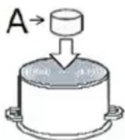
Magnet test
Use small magnet A to test if the dish bottom is magnetic. Only dishes where magnet sticks to the bottom are suitable.
Dish recognition
One of great advantages of the induction hotplate is dish recognition.
When the hotplate is on, the power indicator displays — If you place the dish over that hotplate within the following 10 minutes, the hotplate recognizes the dish and turns on to the pre-set power value.
At the moment you remove the dish from the hotplate, power is suspended. If you place smaller dish upon the hotplate and it is recognized, the hotplate will only use the amount of energy required to heat the dish according to its size.
Hotplate may be damaged if:
• empty hop are heated up.
- you don't use the appropriate pots.
- you use clay dishes which leave scratches on the glass surface.
- you don't wipe the pot bottom.

The use of bad quality cookware or any adapter for non-magnetic cookware invalidates product warranty. In this case, the manufacturer cannot be held responsible for any damage caused to the appliance and / or objects closed to the same.
Power regulation
Heating power of the hotplates may be set at ten different levels.
| Power setting | Purpose |
| 0 | Off, using remaing heat |
| 1-2 | Maintaining warm food, slow simmer of smaller quantities |
| 3 | Slow simmer (continuation of cooking after a powerful start-up) |
| 4-5 | Slow cooking (continuation of larger quantities, roasting larger chunks) |
| 6 | Roasting, Browning |
| 7-8 | Roasting |
| 9 | Start of cooking, roasting |
| A | Automatic heat up |
| P | Especially powerful setting for extremely large quantities of food |
The following chart indicates illustrative use of each power setting.
Energy saving tips
- When buying pots, be careful in selecting size: pot diameter usually refers to the top edge of the pot, which is often larger than the bottom;
- Steam-pressure pots, which use pressure in tightly sealed interior, are especially economic, and save both time and energy. Shorter cooking time leaves more vitamins in food;
- Always leave enough water in steam-pressure pots, otherwise it may result in overheating which may damage both the pot and the appliance;
• Always cover pots with lids of appropriate size; - Use such pot size to accommodate the quantity of food to be prepared.
Hob Control
- After turning the ceramic glass hob on all displays come on for a moment. The hob is ready for operation.
- The hob is fitted with electronic sensors which are switched on if you touch the relevant circle for at least one second.
• Each sensor activation is followed by a sound signal.
- Avoid placing any objects on sensor surface (possible error signalization).
- Always keep the sensor surface clean.
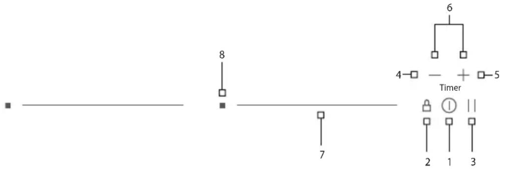
- ON/OFF hob
- Key-lock
- Pause and recall
- (-) Timer
- (+) Timer
- Timer
- Slide control
- Warming
Slide Control
| 03 | 0 |
| 53 | Medium power |
| P3 | Full power |
Turn the hob on

- Press ⏻ for at least one second.
- The hob is now active, and all cooking zone displays indicate
- Now you need to select the next setting within 10 seconds, otherwise the hob switches off.
Turn cooking zones on
After turning the hob, within the next 10 seconds start one of the cooking zones. Set the power level 1-9 by touching the slider control.
- At the first touch, the level is set according to the part of the slider that you touch. Upon the slider control, the LEDs light up, according to the level set.
- By sliding along the slider, the power level setting is changed. By sliding to the right, the level increasing, while sliding to the left decreases the level.
- When you move your finger away from the slider control, the cooking field starts to operate at the level set.
If a specific point of the slider control is pressed for at least 3 seconds, the automatic cooking is activated (see Automatic fast heating).
Turn cooking zones off
- Selected hotplate must be activated.
- By touching the slider sensor at the start, bring the power setting to U. Short beep confirms the OFF position.
Turn the hob off
• The hob is switched off by pressing ⏻
- The sound signal beeps and all indicators go off, except for those hotplates which are still hot and display the warning sign as an indication of the remaining heat.
Key-lock
By activating the key lock protection, you can stop the operation of the appliance and the use of hotplates.
Activation
• The cooktop must be turned on.
- Press ☐ for approximately 1 second, the corresponding LED turns on above the key, the block is active.
- Safety lock prevents the activation of al sensors, except for ⏻ and □
- If the hob is switched off when the lock function is activated, it remains in memory until a new switch on of the hob.
- When set timers end their time, alarms can be switched off pressing ⊖ or ⊕ without need for unlocking the control.
Deactivation
The cooktop must be turned on
Press for 1 second; after that, the unlocking is confirmed by a beep.
Child-Lock
This function can only be activated/deactivated after turning on the hob with and with
all cooking zone at zero level.
Activation
- Press 🔒 and ∥ simultaneously for 3 seconds.
- Function is active and all displays show - Hob control remains locked and switches automatically off after 10 sec.
The Child-Lock deactivates all keys except . Once activated electronic stays locked even if the control is switched off and on again.
Deactivation
- Within 10 sec. press 🔒 and || simultaneously for 3 seconds.
Pause
The execution of the function is possible only if at least one cooking zone is on. In pause mode, the cooking process is suspended and the hob does not deliver power.
Activation
- Press || for at least 1 second, the corresponding LED turns on above the key and all displays show ||
While the Pause function is active
- Any Timer (also Alarm Timer) set before the pause will be stopped during the pause and continue when pause mode is quitted.
• Cooking zones are turned off.
• A selected booster or heat up time automatic function is terminated. - Residual heat calculation and maximum operation time limitations will not be interrupted and keep on working in the background.
- Functional LED's such as Timer, multi-zone, keep on glowing according to their status.
The pause mode can only be active for maximum 10 min.
Throughout the pause time, ① can be used to switch the control off. In this case the pause mode is also deactivated.
Deactivation
- Press ||, the LEDs light up above the cursor of one of cooking zones. - Within 10 seconds press and scroll from the left to the right on the slider cursor of the illuminated area. The LED above the pause key turns off and the condition before the pause mode is restored.
Recall
If the control was accidentally switched off through the main ⏻ all settings can be restored using the recall function.
After switching the control off from the main switch the user has 6s to switch the control on again and then he has another 6s to press in order to recall the settings.
The recall function can only be used if at least one cooking zone was active (cooking level >0) independent from key lock.
Remaining heat indicator
Appliances also features remaining heat indicator. Hotplates are not heated directly, but through return heat radiating from the dish. As long as is on after the hotplate was switched off, the remaining heat may be used for warming up food or for melting.
Even when H disappears, the hotplate may still be hot.

Be careful of burns!
Fast cooking
Extra powerful setting may be additionally switched on for fast cooking. This extra power is used for heating large quantities of food.
After switching on, the extra power is activated for 5 minutes then automatically switches
back on to the maximum normal level 9.
During the time extra power is activated, the power of other hotplates is limited. This is indicated on the power display by intermittently flashing the selected cooking level and limited power for a few seconds.
Activation
- Select the desired cooking zones and move the slider control to the extreme rights to activate the extra power.
• The extra power is active.
. The display shows P
Premature deactivation
Press and scroll on the slider control of the desired zone, until you get to U if you want to turn off the zone, or until the wanted cooking level.
Heat up time automatic
POWER MANAGEMENT SYSTEM
The Power Management system distributes power between the available cooking zones arranged in pairs (such as figures on the side), providing maximum power at a cooking zone and automatically reducing the power available to the other one. The display of the second cooking zone alternates, for a few seconds, the power of cooking chosen and the limited power.

In certain circumstances, the Extra powerful setting function may turn off automatically to protect the electronic components inside the hob.
This function preheats the burner on maximum power in order to bring it rapidly up to the required temperature. After a given time interval, the power level returns spontaneously to the established setting.
It may be switched on in any of the hotplates for all power settings except for setting "9" where power is set at maximum all the time.
Activation
• Automatic cooking mode is activated on any idle hotplate.
- Choose the required continuous cooking level and hold it for 3 seconds.
- The activated heat up time automatic will be displayed through alternating between R and the selected continuous cooking level on the display. As soon as the parboiling time is over, the preselected continuous cooking level is valid again.
- Once the time in the chart below expires, the function is switched off and disappears. You can also switch the automatic cooking mode off anytime by modifying power level.
| Power setting 1 2 3 4 5 6 | 7 8 | |||||||
| Max. power cooking time (minutes) | 40 | 72 120 | 176 | 256 432 | 120 | 192 |
Bridge
With the bridge function two separate cooking zones with the same diameter and equal
power. The bridge function is available for cooking zones showing symbols Un Two cooking zones can be turned on at the same time and controlled with only one operation
Activation
- Whether the two zones are working at a different level, whether they are at level 0, simultaneously press anywhere on the slider controls of the zones.
- Now the two areas work together, the LEDs to the right of the corresponding displays turn on. The level is shown on the display of the control zone, in the meanwhile the controlled zone's display turns off.
- When this function is active, you can set the timer, the LED lights on near both displays of the zones.
- If in 10 uninterrupted minutes no cookware is detected on one of the two elements, the bridge function is automatically deactivated.
- The end of the Function can be done by repeating the simultaneous selection of both cooking elements (the same as activation).
- If the function is deactivated while in operation, than both cooking elements go to level 0 and can then be set again.
Deactivation
Warming
The warming function is used to keep cooked food warm. Hence this function can also be used as melting or simmer function.
Activation
- Press ■ of a cooking zone activates the "warming"
- If is pressed a second time "warming" function ends
Safety switch off
Maximum continuous operation of a particular hotplate is limited, and the duration is displayed in the above chart. When the hotplate is switched off by the safety mechanism, the indicator displays symbols for H case there is any remaining heat left.
| Power setting | Minutes lapse prior safety switch off |
| Warming 120 | |
| 1 522 | |
| 2 402 | |
| 3 318 | |
| 4 258 | |
| 5 210 | |
| 6 168 | |
| 7 138 | |
| 8 114 | |
| 9 90 | |
| P 10 |
Example:
Set the hotplate to power level 5 and leave it operate for some time. If you do not change the above setting, the safety mechanism will switch the hotplate off after 210 minutes.
Protection from overheating
Induction hotplate is also fitted with safety device against overheating which protects electronic parts from damages. This device operates on several levels. When temperature of the hotplate excessively rises, it switches on two-stage fan. If this is not enough, extra powerful heating is deactivated, and finally the safety device either reduces the heating power of certain hotplates or turns them off completely. When the hotplate cools off, the full power of hotplate is again available.
Timer
Use a timer facilitates cooking by setting the time of hotplate operation. For each zone it's possible to set an independent timer
Activation
- The cooktop must be turned on and the zone where you want to set the timer must be working.
- Simultaneously press ⊖ and ⊕, the timer's display shows 0.00 and 4, of the first active cooking zone from the left, lights on
- Simultaneously press and as many times as necessary, to select the zone where you want to set the timer. lights on only for active zooking zones.
- Within 10 seconds since pressing ⊖ and ⊕ set the timer value by pressing ⊖ or ⊕.
• The value of the timer can be displayed:
- in minutes and seconds up to 9min59sec;
- in hours and minutes up to 9h59min, in this case the word "min" is shown under the timer's display.
Operation time can be set for each hotplate separately.
Changing pre-set cooking time
Cooking time can be changed anytime during the operation.
- Simultaneously press and
- Simultaneously press ⊖ and ⊕ as many times as necessary, to select the zone where you want to set the timer. ✉ light on only for the active cooking zones.
- Within 10 seconds press and to modify the time.
Checking remaining cooking time
- Last set timer is always displayed ( 43 has a lighting stronger than the others);
- Simultaneously press and ① - Simultaneously press 一 and ② as many times as necessary, to select the zone of which you want to see the remaining time. The zone is identified by the lighting on ③ - The timer's display will display the remaining time of the selected cooking zone.
Deactivation
When pre-set time elapses, a beep signals the end, and the hotplate is switched off. Switch off the alarm by pressing the sensor or it switches off automatically after 2 minutes.
If you want to deactivate the timer prior the end of pre-set time:
- Simultaneously press and;
- Simultaneously press and as many times as necessary, to select the zone where you want to set the timer. The zone is identified by the lighting on of:
- Press to the value.
- is turned off and the timer is deactivated.
Alarm
Timer can be used as alarm also if it is already employed in timer control of one of the hotplates.
Timer setting
With the hob off:
- Press Ⓘ to activate the cooking hob;
- Simultaneously press and to activate the alarm. The timer's display shows 0.00. If some cooking zone is active, of the first active cooking zone from the left, lights on;
- Simultaneously press and as many times as necessary to select the alarm. The respective is located between or;
- The timer value is set by pressing or ☐
- It's possible setting the time in minutes and seconds or, in hours and minutes also for the alarm.
Switching the alarm off
When the pre-set time expires a beep is heard which you can either turn off by pressing - or + or leave it to turn off automatically after 2 minutes.
If you want to switch the timer off prior expiry of pre-set time:
- Simultaneously press and
- Simultaneously press and as many times as necessary to select the alarm, light on;
- Press until the value. The alarm is deactivated.
Chef Cook function
This function gives the possibility to handle the pots like in a restaurant kitchen. The user can slide over the cooktop with the cookware, and on different positions the cookware gets different power levels.
Activation
- Press || and ⊕ keys simultaneously.
- Function is active and the power level of each zone is indicated in the 7-segment display of that zone.
Deactivation
- Press again and keys simultaneously.
The Chef Cook function comes with preset levels for each cooking zone but the user can modify them with the slider control of each zone. When the function is deactivated every power level returns to its pre-set value.
SAFETY FUNCTIONS AND ERROR DISPLAY
- During the warranty period, only a service center authorized by the manufacturer may carry out any repairs.
- Before making any repairs, make sure the appliance is disconnected from the power mains either by removing the fuse or by disconnecting the power plug from the wall outlet.
- Unauthorized tampering with and repairs of the kitchen range (cooking hob) can result in electric shock or short circuit; hence, do not attempt to perform any repairs by yourselves. Leave such tasks to an expert or an authorized service unit.
- In case of minor faults or problems with the appliance operation, check the following instructions to see whether you can eliminate the causes by yourselves.
- Elimination of any errors or warranty claims that resulted from improper connection or use of the appliance is not covered by our warranty. In such cases, the costs of repair are borne by the user.
| ERROR CODE | ERROR DESCRIPTION REMEDY | |
| Permanent use of sensors; Control unit cuts off after 10 sec. Water or cooking utensils on the glass above the control unit.. | Cleaning of the operational surface. If the problem persists, Contact authorized center for technical assistance, specifying the error code | |
| L | NO error!Child.lock activated | Deactivate child-lock |
| Inappropriated pan Use appropriate pan. If the problem remainsContact authorized center for technical assistance - specify the error code. | ||
| E8 | Incorrect cooling fan operation Air exhaust blocked, for example by paper.Or fan defectiveContact authorized center for technical assistance, specifying the error code. | |
| E3 | Inappropriated pan Use appropriate pan. If the problem remainsContact authorized center for technical assistance | |
| E2 | Excessive overheating of hob Do not heat empty pans.Use appropriate pots for induction.Let the hob cool down.If the problem persists, contact the authorized technical assistance center, specifying the error code. | |
| Er21 | ||
| Er22 | ||
| Er20 | ||
| Er36 | ||
| Er31 | ||
| Er47 | ||
| Er40 | ||
| EA | Contact authorized center for technical assistance, specifying the error code. | |
| EH | ||
| U400 | ||
| E4 | ||
| E5 | ||
| E6 | ||
| E7 | ||
| E9 | ||
POWER LIMITATION SETTING
The appliance is generally configured to the maximum available power, shown in the technical data table.
However, an operating mode with power limitation can be set. In this way, the maximum power supplied by the hob is limited to a fixed value.

The power limitation setting must ONLY be performed by a specialized technician.
To set the power limitation, do the following:
- Connect the hob to the power supply.
- Within two minutes, access the Service Menu by simultaneously pressing the 🔒 and 11 keys until you hear an acoustic signal.
- Press two illuminated slider cursors until you hear a second beep. The "Timer" display shows [CF6].
- Press || button. The "Timer" display shows [PHA].
- Use slider control (left end , right end +) to select desired power level. Selected level is shown on display of a cooking zone. The correspondence between the power levels and limitation values are shown in table below.
- To confirm selection and exit the Service Menu, press and keys simultaneously.
To exit the Service Menu without making changes, press. Ⓘ
WARNING! The power level selected must be according to the fuses installed.
Power level chart
| 0 (Default) | 7400 W |
| 1 | 1000 W |
| 2 | 1500W |
| 3 | 2800 W |
| 4 | 3500 W |
| 5 | 3700 W |
| 6 | 4500 W |
| 7 | 6000 W |
OPERATIONGB
This device allows you to choose the operating mode (suction or filtering) depending on the installation.
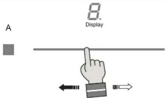
When you first turn it on, for about ten seconds the display shows which mode is active.
Filtering: the display shows the letter F
Suction: the display shows the letter A
During this phase, you can change the mode by acting on the slider:

natural_image
Illustration of a hand pointing upward with a horizontal line above (no text or symbols)To confirm the desired mode, press the button

To recall the choice of the operating mode, remove and re-apply voltage to the device.
Note: if the voltage is lost again, the device displays the last setting selected; to confirm, press the button ■ or wait 15 seconds; to change this mode, use the slider to select the preferred mode; to confirm, press the button ■
Turning the suction on and off:
-
Touch the slider
-
Set the extractor speed level within 3 seconds by touching the slider control (from 1 to 9). The extractor turns on at the set extraction speed.
Set a higher or lower level using the slider control.
-
Set the extractor speed level to "0" to turn off the extractor.
-
Turn off the induction hob by touching the on/off button.
Note: in filter mode, when the device is turned off, the extraction remains on for 20 minutes at minimum speed, to allow any condensation that may have formed during the cooking phases to evaporate.
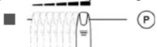
Intensive:
You can use the Boost function to extract at the highest level for a period of up to 6 minutes. (In recirculation mode there is no time limit and the Boost function remains active.)
- Move the slider until "P" appears on the display.
Once the maximum allowed time has elapsed, the extractor speed will be reduced to level 9.
Note: In recirculation mode there is no time limit and the Boost function remains active.
- Set the extractor speed level to "0" to turn off the extractor.
To recall the choice of operating mode, remove and reconnect the power to the device.
- Turn off the induction hob by touching the on/off button.
Automatic Mode
In automatic extraction mode, the extraction level automatically adapts to the use of the cooking zones.
- Press the button.
- To deactivate this mode, press again or use the slider.
Grease filter saturation warning
After 30 hours of hood operation, the symbol lights up to indicate the need to clean the metal greasefilters. Thisalarminhibits the suction operation until reset, to allow the water collection traytobe emptied. (This operation must be carried out as needed and in any case must be done at each filter reset).
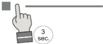
To reset this warning, press the button for 3 seconds
Odor filter saturation warning
After 120 hours of hood operation, the symbol 🎨 lights up indicating the need to clean/replace the active carbon filters; see the paragraph on the maintenance of these filters. To reset this warning, press the button for 3 seconds
Maintenance Mode:
When maintenance mode is activated, the extraction flap will automatically open without turning on the motor, allowing access to the extraction area and the compartments for the grease and odor filters, so that cleaning and maintenance operations can be carried out.
To activate maintenance mode, press and hold the button for 3 seconds.
To exit maintenance mode, switch off the appliance by pressing the power button.
Note: The extraction continues to operate even when the cooking zones are paused.
MAINTENANCE
Cleaning
First use
- Use a damp cloth to clean and dry the glass surface before using it for the first time.
- It is recommended to dry the appliance after having cleaned it with a damp cloth, in order to prevent the build-up of limescale.
Daily cleaning
- Although food spills cannot burn into the glass, we nevertheless recommend you to clean the hob immediately after use.
- Best for daily cleaning is a damp cloth with a mild cleaning agent.
- Dry with kitchen paper or a dry teacloth.
Stubborn stains
- Stubborn stains can also be removed with a mild cleaning agent such as washing-up liquid.
- Remove watermarks and lime scale with vinegar.
• Metalmarks (caused by sliding pans) can be difficult to remove. Special agents are available. - Use a glass scraper to remove food spills. Melted plastic and sugar is also best removed with a glass scraper.

Never use abrasives. They leave scratches in which dirt and lime scale can accumulate. Never use anything sharp such as steel wool or scourers.
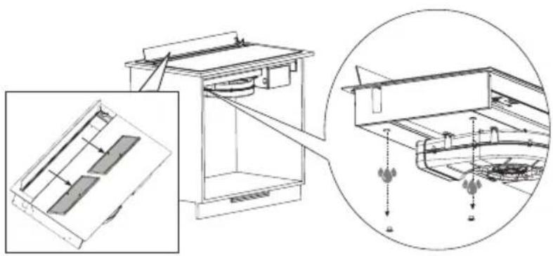
Filters and collect tray
Grease filters
In the display of the extraction unit, 'F' and 'G' will be shown alternately after 30 operating hours of the extraction unit. The grease filters should now be cleaned.
These must be cleaned once a month (or when the filter saturation indication system indicates this necessity). Do not use aggressive cleaning agents and preferably clean the filter manually or in the dishwasher at a low temperature and with a short program. Place the filters with the opening downwards in the dishwasher so that the water can run out. The cleaning agents used in dishwashers make the aluminum dull faster. This is normal.
After the cleaning and replacing of the grease filters, reset the memory of the filter saturation indication.
MAINTENANCE
Recirculation filters - (cod.AFCFCAISOB01)
Filters can be restored in the oven, better if fan-assisted.
Temperature of the oven should be 150^ - 180^ , higher temperatures could damage the filters. It is better to place the filter bricks on the oven's grid, non pre-heated, and let them cool down completely before removing.
The time needed to restore the filters is at least two hours or even more, depending on the cooking intensity. Restoring should be done only in a well-ventilated place.
Do not wash the filters in the dishwasher.
Recirculation filters can be restored many times, but for a better efficiency we recommend to replace every 1 years.
Recirculation filters Twin- (cod.AFCFCAISOB02)
The used filters in this hob are combined filters for grease and odour filtering. These TWIN filters are regenerable and need periodical maintenance.
- After 30 operating hours, 'F' and 'G' will be shown alternately in the display of the extraction unit; it is necessary to wash the TWIN filters.
- The twin filters must be washed without any detergents.
- The twin filters can be washed in the sink with hot water or can be put in the dishwasher with a quick wash program, without any other dishes (to avoid the presence of fats or oils) and at recommended temperatures not exceeding 60/65 °C.
- The twin filters can be dried naturally by covering them with a clean, residue-free cloth or in an oven with top and bottom heat at a temperature of 80^ for no longer than 1 hour.
You need to replace the TWIN filters:
- when you notice that the odour filtering is not sufficient anymore (the average time is after 240 operating hours).
• after 1 year of use at the latest.
- when the filters are clearly damaged.
ATTENTION: Drying must never be carried out with air flows. It is important that the TWIN filters are properly dried before installation. After the maintenance, reset the memory of the filter saturation indication.