RTH-400A - Lawn mower MSW - Free user manual and instructions
Find the device manual for free RTH-400A MSW in PDF.

User questions about RTH-400A MSW
0 question about this device. Answer the ones you know or ask your own.
Ask a new question about this device
Download the instructions for your Lawn mower in PDF format for free! Find your manual RTH-400A - MSW and take your electronic device back in hand. On this page are published all the documents necessary for the use of your device. RTH-400A by MSW.
USER MANUAL RTH-400A MSW
This User Manual has been translated using machine translation. We have made every effort to ensure the translation is accurate, but please note that automated translations are not perfect and are not meant to replace human translators. The official version of the User Manual is in English. Any differences between the translated version and the original English are not legally binding. If you have any questions about the accuracy of the translation, please refer to the English version, which is the official reference. More language versions are available upon request via info@expondo.com.
Technical data
| Parameter description | Parameter value |
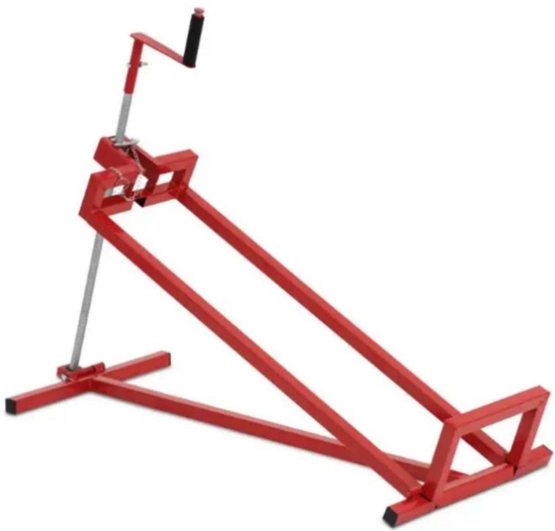
| Product name | Lawn Mower Jack |
| Model | MSW-RTH-400A |
| Maximum Load [kg] | 400 |
| Angle adjustable [°] | 45 |
| Dimensions [Width x Depth x Height; mm] | 493 x 1142 x 950 |
| Weight [kg] | 10.25 |
natural_image
Red metal frame device with a vertical support and metal handle, shown against a white background (no text or symbols visible)User guide and maintenance
Warning: To reduce the risk of injury, always follow these basic safety guidelines:
- Read all instructions before using this product.
- Keep this manual for future reference.
Thank you for choosing this product.
Attention: Before lifting any load, ensure you understand how to use this tool correctly. Improper use of the lawn mower lifter can lead to serious injury. Any use other than described in this manual may damage the tool and pose a safety hazard.
Safety instructions
For safe and proper use:
- Only use the lawn mower lifter for lifting operations.
- Keep children away from the lawn mower lifter; do not allow them to use or play with it.
- Ensure no one is near the load while using the lawn mower lifter.
-
Do not leave the lawn mower lifter unattended while in use.
-
Do not exceed the lifter's capacity. Overloading can damage the lifter and may lead to injury or material damage.
- Use the lawn mower lifter on hard, stable surfaces only. Using it on soft or uneven surfaces can make it unstable, causing the load to fall.
- Always secure the load along the lateral reinforcement of the lifter on the side opposite the screw spindle. An unsecured or uneven load may damage the lifter or cause it to slide and fall.
- Inspect the lifter for completeness and functionality before each use. Perform a test lift without any load to confirm.
- Ensure the riding lawn mower driver has exited the seat before lifting the mower.
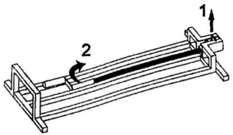
Assembly before use
- Place the lawn mower on a horizontal, stable surface.
- Remove the locking peg.
- Position the screw crank upwards.
Tip: For optimal performance, apply grease to the screw before use.
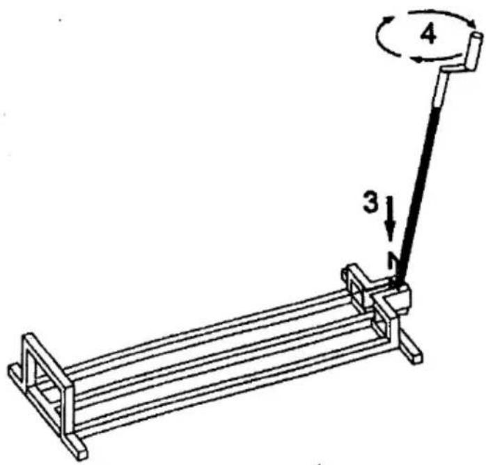
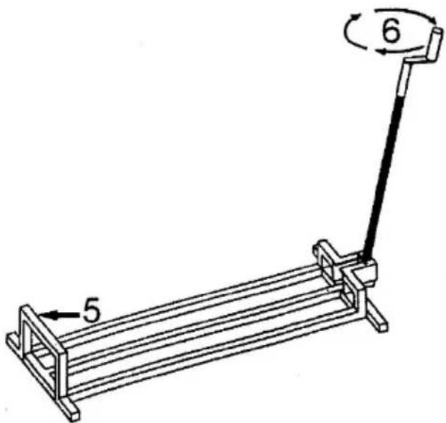
Operation
- Insert the peg to lock the screw crank in the upright position.
- Turn the spindle clockwise to lift the lawn mower.
Lifting a lawn mower
Place the lawn mower on a flat, hard surface.
- Position the lawn mower on the lifter by aligning its base against the lateral reinforcement opposite the screw crank.
Note for riding lawn mowers: Position the back of the mower on the lifter, with the rear wheels resting against the lateral reinforcement opposite the screw crank.
- Turn the handle clockwise to lift the lawn mower 2-3 cm off the ground. Ensure the lawn mower is balanced before continuing to lift.
If imbalance occurs, turn the handle counterclockwise to lower the lawn mower back to the ground. Adjust the mower by moving it forward or backward, then resume lifting.
Attention: Do not lift the lawn mower too high, as this increases the risk of tipping over. Lift it just enough to safely proceed with your work.
Maintenance
When the lawn mower lifter is not in use:
- Return the screw crank to the rest position.
- Grease the screw regularly—approximately every 3 months.
- Inspect for rust every 3 months. If rust is present, clean it with an oil-soaked cloth.

natural_image
Red metal frame device with a vertical support and metal handle, no visible text or symbolsTätigkeit
natural_image
Red metal frame with a vertical handle and support structure, no visible text or symbolsPraca z urządzeniem
natural_image
Red metal frame with a vertical support and metal handle, no visible text or symbolsČinnost
natural_image
Red metal frame device with a vertical support and metal handle, no visible text or symbolsOpération
natural_image
Red metal frame device with a vertical support and metal handle, no visible text or symbolsOperazione
natural_image
Red metal frame with a vertical support and metal handle, no visible text or symbolsActividad
natural_image
Red metal frame device with a vertical support and metal handle, no visible text or symbolsTevékenység
Fúnyíró emelése
natural_image
Red metal frame device with a vertical support and metal handle, shown against a white background (no text or symbols visible)Handling
natural_image
Red metal frame device with a vertical support and metal handle, shown against a white background (no text or symbols visible)Käyttö
Ruohonleikkurin nostro
natural_image
Red metal frame device with a vertical support and metal handle, no visible text or symbolsAnvendelse
natural_image
Red metal frame device with a vertical support and metal handle, no visible text or symbolsBruk
natural_image
Red metal frame device with a vertical handle and support structure (no text or symbols visible)Användning
natural_image
Red metal frame device with a vertical support and metal handle, shown against a white background (no text or symbols visible)Utilização
natural_image
Red metal frame with a vertical handle and support structure, no visible text or symbolsPrevádzka
natural_image
Red metal frame with a vertical support and metal handle, no visible text or symbolsОперация
natural_image
Red metal frame device with a vertical support and metal handle, no visible text or symbolsΛειτουργία
natural_image
Red metal frame device with a vertical support and metal handle, no visible text or symbolsOperacija
-
Umetnite klin da zaključate polugu s vijkom u uspravnom položaju.
-
Okrenite vreteno u smjeru kazalike na satu za podizanje kosilice.

Podizanje kosilice
natural_image
Red metal frame device with a vertical support and metal handle, no visible text or symbolsOperacija
natural_image
Red metal frame device with a vertical support and metal handle, no visible text or symbolsOperatiunea
natural_image
Red metal frame with a vertical support and metal handle, no visible text or symbolsDelovanje
For the disposal of the device please consider and act according to the national and local rules and regulations.
CONTACT
expondo Polska sp. z o.o. sp. k.