
DKVM-450 - Switch D-LINK - Free user manual and instructions
Find the device manual for free DKVM-450 D-LINK in PDF.

| Product Type | KVM Switch (keyboard, video, mouse) |
| Brand | D-Link |
| Model | DKVM-450 |
| Number of Ports | 16 ports (combined PS/2 and USB) |
| Power Supply | Included power adapter |
| Dimensions | Approximately 44 x 17 x 4.5 cm (19-inch rack standard) |
| Weight | Approximately 2.5 kg |
| Main Features | Control up to 16 PCs via one console; supports daisy-chaining up to 3 levels (64/256/4096 PCs); selection via front panel buttons, keyboard hotkeys, or OSD; hot-pluggable |
| Console Connectors | 1 VGA port, 1 PS/2 keyboard port, 1 PS/2 mouse port |
| PC Connectors | 16 combined ports (VGA + USB + PS/2) via 4-in-1 cables |
| Rack Mounting | Mounting brackets included for standard 19-inch rack |
| Maintenance and Cleaning | Unplug the device before cleaning; use a dry, non-abrasive cloth |
| Safety | Turn off computers before installation; disconnect power cords for PCs with keyboard power-on feature |
| Spare Parts and Repairability | 4-in-1 combo cables available from retailer; standard power adapter |
| General Information | Manual available in French and other languages; technical support by phone and D-Link website |
Frequently Asked Questions - DKVM-450 D-LINK
User questions about DKVM-450 D-LINK
0 question about this device. Answer the ones you know or ask your own.
Ask a new question about this device
Download the instructions for your Switch in PDF format for free! Find your manual DKVM-450 - D-LINK and take your electronic device back in hand. On this page are published all the documents necessary for the use of your device. DKVM-450 by D-LINK.
USER MANUAL DKVM-450 D-LINK
Building Networks for People
Hardware Quick Installation Guide PS2/USB Combo KVM Switch
This document will guide you through the basic installation process for your new D-Link KVM Switch.
DKVM-440 / DKVM-450
Quick Installation Guide
Documentation also available on
CD and via the D-Link Website
About This Guide
This guide contains step-by-step instructions for setting up your D-Link KVM Switch. Please note that the model you have purchased may appear slightly different from those shown in the illustrations.
Unpacking the Product
Open the shipping carton and carefully unpack its contents. Please consult the packing list located in following information to make sure all items are present and undamaged. If any item is missing or damaged, please contact your local D-Link reseller for replacement.
- (1) 8-Port or 16-Port Combo KVM Switch
- (1) CD
- (1) Quick installation Guide
- (4) 4 in 1 PS2/USB Combo KVM cable
- (1) Power Adaptor
- (1) Rack Mount Bracket Kit Set
Product Overview
Front Panel
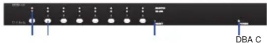
Figure 1. DKVM-440 Front Panel
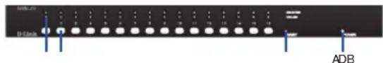
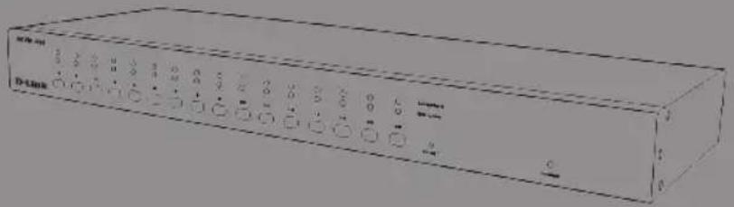
Figure 2. DKVM-450 Front Panel
Device Status LEDs and Buttons
| Item | Feature Description | Red |
| A | Status LEDs Selected | (Red):A Red LED indicates that the corresponding PC is selected.Online (Green):A Green LED indicates that the corresponding PC is online. |
| B | Switch Button Press the | button corresponding to the computer you would like to select for control via console. |
| C | Reset Switch Press the | Reset switch when you would like to reset the device. The reset switch must be depressed using a thin object like the end of a paper clip, or a ball point pen. |
| D | Power LED Indicates that the device is powered on. | |
Table 1. Front Panel Descriptions
2 ◆ D-Link KVM Switch Quick Installation Guide
Rear Panel
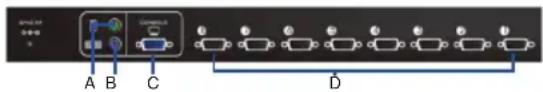
Figure 3. DKVM-440 Rear Panel
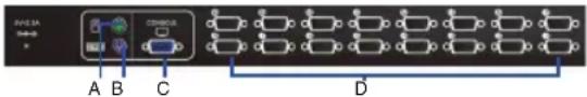
Figure 4. DKVM-450 Rear Panel
KVM Port Connections
| Item Feature | Description |
| A PS/2 Console Mouse Port | Connects to the mouse cable of the controlling console PC |
| B PS/2 Console Keyboard Port | Connects to the keyboard cable of the controlling console PC |
| C Console Port (VGA) | Connects to the monitor cable of the controlling console PC |
| D Power LED Connects to the KVM combo cable of the target workstations | |
Table 1. Rear Panel Descriptions
Installation
Precautions:
- Please turn off computers and attached devices when you begin installation of the KVM Switch.
- For computers with Keyboard Power On function, please unplug the power cords in advance. Otherwise, the switch may not work properly.
- If your computers run Windows 98, please connect the KVM switch to computers via PS/2 ports. Windows 98 does not support first time installation through USB HID installation driver.
- Some older computers may require you to enable USB in BIOS to make the USB interface work.
Console connection:
Plug the keyboard, mouse and monitor into the console ports on the rear panel of the KVM Switch.
System connection:
Use the custom combo cable to connect your computers. Refer to the figures and instruction shown below for information about connecting the KVM to PCs.
natural_image
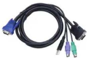
Coiled black cable with blue and green connectors, no visible text or symbolsFigure 5. Custom combo 4-in-1 cable
Note: Please contact your reseller to purchase the custom combo 4-in-1 cables if needed.
You can connect KVM switch to computers using one of the three methods shown below:
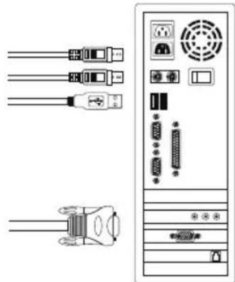
A. Connect USB, PS/2 (keyboard/mouse) and VGA connectors to computers. We recommend that users connect computers in the manner shown below. (Figure 6)
natural_image
Diagram showing connections between server racks and a central tower (no text or labels)Figure 6. DKVM-440 Front Panel
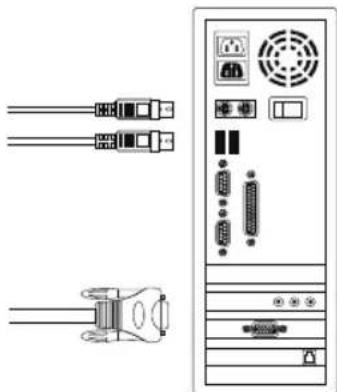
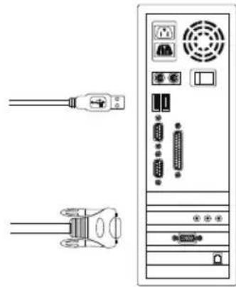
B. Connect only PS/2 (keyboard/mouse) and VGA connectors to computers. (Figure 7)
natural_image
Diagram of a desktop computer tower with connected cables and ports (no text or labels)Figure 7. DKVM-440 Front Panel
C. Connect only USB and VGA connectors to computers. (Figure 8).
natural_image
Diagram showing two cables connected to a server tower with ports and connectors (no text or symbols)Figure 8. DKVM-440 Front Panel
Cascade Chaining
The KVM switch supports cascades of up to 3 levels. Control up to 64/256/4096 PCs from a single console. Cascaded units do not require any special configuration. A cascade configuration expands the system's capabilities and allows you to select computers connected to the Master or Slave. Once connected, the KVM Switches will automatically configure themselves appropriately as the Master or Slave.
To install a cascade chain, please follow the instruction below.
A. Power off any attached computers/devices before installing the KVM Switch.
B. Use the custom combo cable set (See Figure 5), to connect one or more Slave KVM Switches to any PC port of Master KVM Switch. The KVM to KVM must be connected through a PS/2 connection. (Please refer to Figure 6 & Figure 7).
C. Plug in the power adapter of the first level Master KVM Switch and connect Master KVM switch to computers.
D. Plug in the power adapter for each level Slave KVM Switch and connect Slave KVM switch to computers.
E. The power on sequence should be:
- Master KVM Switch
- Second level Slave KVM Switch (connecting to Master KVM Switch) if needed.
- Third level Slave KVM Switch (connecting to second level Slave KVM Switch) if needed.
- All computers connecting to Master/Slave KVM Switch.
F. After all KVM Switches are powered by power adaptors, turn on the computers.
Initial Plug-in Process:
Please plug in the Master KVM Switch first before turning on any other devices like monitor or computers.
Hot plugging and hot swapping:
The KVM switch supports hot plugging and hot swapping.
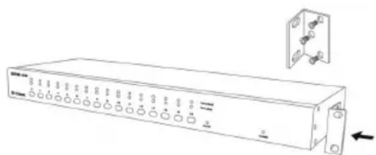
Rack Mounting
natural_image
Line drawing of a rectangular electronic device with multiple ports and an attached mounting bracket (no text or symbols)Figure 9. DKVM-440 Front Panel
Figure 7 shows you how to attach mounting brackets to the KVM Switch unit for a standard 19-inch rack cabinet.
- Attach the mounting brackets onto the sides of the KVM Switch unit using screws. (See Figure 9)
- Install the KVM Switch unit into the rack cabinet.
Operation
You can select a computer to control with the KVM switch using the front panel buttons, hotkeys, or OSD.
- Button Operation Press the front panel button to select the PC and operate it.
- Hotkey Operation Please refer section 6: Hotkey Operation.
- OSD Operation Please refer section 7: OSD Operation.
Additional Information
In addition to the user manual, the Master CD also includes many device configuration examples. Additional help is available through D-Link worldwide offices listed in the appendix of the User Manual or online. For support, please visit the website http://support.dlink.com.tw, which will redirect you to your regional D-Link website.
Technical Support
United Kingdom (Mon-Fri) website: http://www.dlink.co.uk FTP: ftp://ftp.dlink.co.uk Home Wireless/Broadband 0871 873 3000 (9.00am-06.00pm, Sat 10.00am-02.00pm) Managed, Smart, & Wireless Switches, or Firewalls 0871 873 0909 (09.00am-05.30pm) (BT 10ppm, other carriers may vary.)
Ireland (Mon-Fri) All Products 1890 886 899 (09.00am-06.00pm, Sat 10.00am-02.00pm) Phone rates: €0.05ppm peak, €0.045ppm off peak times
Appendix: Product Statement
EMI Statement
FCC Warning
This equipment has been tested and found to comply with the limits for a Class B digital device, pursuant to Part 15 of the FCC Rules. These limits are designed to provide reasonable protection against harmful interference when the equipment is operated in a commercial environment. This equipment generates, uses, and can radiate radio frequency energy and, if not installed and used in accordance with this manual, may cause harmful interference to radio communications. Operation of this equipment in a residential area is likely to cause harmful interference in which case the user will be required to correct the interference at his own expense.
4 ◆ D-Link KVM Switch Quick Installation Guide
NOTES
natural_image
Coiled black TV network cable with multiple ports (no text or symbols visible)natural_image
Diagram of a desktop computer tower with connected cables and connectors (no text or labels)natural_image
Diagram of a desktop computer tower with connected cables and connectors (no text or labels)natural_image
Diagram of a desktop computer tower with connected cables and connectors (no text or labels)natural_image
Line drawing of a rectangular electronic device with multiple ports and an attached electrical outlet (no text or symbols)natural_image
Black cable with multiple colored connectors (blue, purple, green, black) tied around a white connector (no text or symbols visible)natural_image
Diagram of server rack connections showing cable, socket, and drive components (no text or labels)natural_image
Diagram of a desktop computer tower with connected cables and connectors (no text or labels)natural_image
Diagram showing two connected cables (wire and plug) next to a server rack with ports and indicators (no text or labels)natural_image
Line drawing of a rectangular electronic device with multiple ports and connectors, no text or symbols present.Assistance technique
Figura 2. Panel frontal del DKVM-450
Instalación
Precauciones:
natural_image
Coiled black TV network cable with multiple ports (no text or symbols visible)natural_image
Diagram of a desktop computer tower with connected cables and ports (no text or labels)Figura 6. Panel frontal del DKVM-440
natural_image
Diagram of a desktop computer tower with connected cables and connectors (no text or labels)Figura 7. Panel frontal del DKVM-440
natural_image
Diagram of a desktop computer tower with connected cables and connectors (no text or symbols)Figura 8. Panel frontal del DKVM-440
Enlace en cascada
natural_image
Line drawing of a rectangular electronic device with multiple ports and connectors, no text or symbols present.Figura 9. Panel frontal del DKVM-440
This equipment has been tested and found to comply with the limits for a Class B digital device, pursuant to Part 15 of the FCC Rules. These limits are designed to provide reasonable protection against harmful interference when the equipment is operated in a commercial environment. This equipment generates, uses, and can radiate radio frequency energy and, if not installed and used in accordance with this manual, may cause harmful interference to radio communications. Operation of this equipment in a residential area is likely to cause harmful interference in which case the user will be required to correct the interference at his own expense.
NOTES
natural_image
Coiled black TV network cable with multiple ports (no text or symbols visible)natural_image
Diagram of a desktop computer tower with connected cables and connectors (no text or labels)Figura 6. Pannello frontale dello switch DKVM-440
natural_image
Diagram of a desktop computer tower with connected cables and connectors (no text or labels)Figura 7. Pannello frontale dello switch DKVM-440
natural_image
Diagram showing two connected cables (USB and AC) next to a server rack with ports and indicators (no text or symbols present)Figura 8. Pannello frontale dello switch DKVM-440
natural_image
Line drawing of a rectangular electronic device with multiple ports and connectors, shown with an inset view of a bracket (no text or symbols)Figura 9. Pannello frontale dello switch DKVM-440
http://www.dlink.it/support
- Hardware Quick Installation Guide PS2/USB Combo KVM Switch
- About This Guide
- Unpacking the Product
- Product Overview
- Installation
- Precautions:
- Console connection:
- System connection:
- Cascade Chaining
- Initial Plug-in Process:
- Hot plugging and hot swapping:
- Operation
- Additional Information
- Technical Support
- Appendix: Product Statement
- EMI Statement
- FCC Warning
- Assistance technique
- Instalación
- Precauciones:
- Enlace en cascada
Brand : D-LINK
Model : DKVM-450
Category : Switch