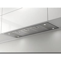
EVO - Range hood Pando - Free user manual and instructions
Find the device manual for free EVO Pando in PDF.


| Product type | Decorative range hood |
| Brand | Pando |
| Model | EVO |
| Installation | Wall, island, ceiling or built-in (depending on version) |
| Control type | Electronic keypad, invisible touch, RF remote control (depending on version) |
| Lighting | Adjustable LED, brightness and color temperature adjustable (Pando LED) |
| Motor speeds | 3 to 4 speeds + intensive speed (Booster) |
| Timer | Last Time function (5 min) and automatic safety shut-off (5 h) |
| Maximum airflow | Up to 750 m³/h depending on motor |
| Noise level | Varies by speed and motor (see technical data sheet) |
| Filters | Washable anti-grease metal filter (aluminum or stainless steel) + optional activated carbon filter (FCA or FCLR AE) |
| Filter maintenance | Metal filter: wash every 15 days in dishwasher (short cycle, max 50°C) or by hand. Carbon filter: replace every 3-6 months or regenerate (FCLR AE) every 3 months |
| Power supply | 220-240 V ~ 50/60 Hz, single-phase |
| Rated power | Varies by motor (e.g., 125W to 750W) |
| Minimum installation distance | 65 cm above a gas cooking surface (or more if specified by the cooktop manufacturer) |
| Duct diameter | 120 mm, 150 mm or 200 mm depending on motor version |
| Special function | Pando AIR Clean (automatic air renewal 10 min/h) |
| Warranty | 3 years (excluding wear parts and aesthetic damage) |
| Materials | Stainless steel, enamel, Corian or Dekton depending on finish |
| Package contents | Range hood, user and installation manual, mounting accessories, remote control (depending on version) |
Frequently Asked Questions - EVO Pando
User questions about EVO Pando
0 question about this device. Answer the ones you know or ask your own.
Ask a new question about this device
Download the instructions for your Range hood in PDF format for free! Find your manual EVO - Pando and take your electronic device back in hand. On this page are published all the documents necessary for the use of your device. EVO by Pando.
USER MANUAL EVO Pando
natural_image
Modern minimalist interior design featuring a multi-level staircase with open shelves and decorative panels, no visible text or symbols.Pando
integralcooking
HOTTES DÉCORATIVES DECORATIVE COOKER HOODS

User and installation Manual. Guarantee Certificate.
natural_image
Diagram of a mechanical or fluid system with directional arrows and a vertical barrier, no text or symbols present.Fig.1
natural_image
Diagram of a mechanical or fluid system with directional arrows and a labeled point A, no readable text or symbols present.Fig.2
2. RECOMMANDATIONS À PRENDRE EN COMPTE AVANT L'INSTALLATION
natural_image
Simple line drawing of a faucet with a red X-shaped prohibition symbol (no text or labels)MAUVAIS CORRECT MIEUX
natural_image
Close-up of a textured, dark gray rectangular object with no visible text or symbols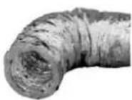
• DISTANCES ET TAILLE APPROPRIÉE :

Moteur

Faux plafond.

5.3. MOTEUR MURAL DE FAÇADE:
natural_image
Two technical line drawings of a building interior with ventilation ducts and storage compartments (no text or symbols)6. CARACTÉRISTIQUE DU CONDUIT D'ÉVACUATION SELON LA VERSION DU MOTEUR.
| tunable | 2700......6000°k 2700......4000°k |
S.I.A. Safety ARRÊT DE SÉCURITÉ AUTOMATIQUE (5h)
natural_image
Two simple icons: a circular icon with a plus sign and a circular icon with a minus sign, both radiating outward from each other (no text or symbols)• ALARME SATURATION FILTRES:
- FILTRES MÉTALLIQUES:

natural_image
Technical line drawing of a rectangular frame with two internal compartments and mounting holes, featuring a circular component and a sun icon (no text or symbols)natural_image
Metallic rectangular electronic component with internal slots and mounting holes (no visible text or symbols)Échecs de communication:
natural_image
Diagram of a mechanical device interacting with two grid-patterned panels, labeled A (no text or symbols present)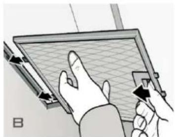
natural_image
Illustration of hands interacting with a grid-patterned panel or board (no text or symbols visible)natural_image
Illustration of a blue washing machine with a door open, showing internal components (no text or symbols)8.2. NETTOYAGE ET ENTRETIEN DES FILTRES
FILTROS LABYRINTHE INOX
natural_image
Technical line drawing of a mechanical ventilation unit with airflow arrows (no text or symbols)natural_image
3D architectural rendering of a modern building facade with horizontal panels and a curved green component, no visible text or symbols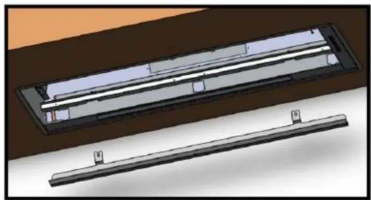
natural_image
3D CAD model of a rectangular electronic component with internal parallel strips, shown from two different angles (no text or symbols)8.2. NETTOYAGE ET ENTRETIEN DES FILTRES
8.2. NETTOYAGE ET ENTRETIEN DES FILTRES
natural_image
Illustration of three different kitchen air purifiers with grid patterns, shown from different angles (no text or symbols present)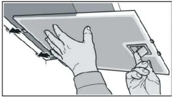
natural_image
Illustration of hands interacting with a tablet device (no text or symbols visible)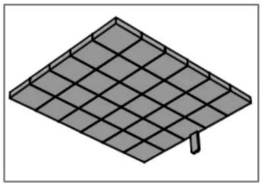
natural_image
Isometric illustration of a solar panel array with a single mounting bracket (no text or symbols)8.2. NETTOYAGE ET ENTRETIEN DES FILTRES
ÉLIMINATION OU RECYCLAGE DES FILTRES FCA, FCLR AE Y FCCR AE:
- LED CARRÉ 2.1W, 12vDC, 700Ma.
natural_image
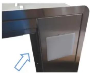
Close-up of a metallic door with a white square vent, showing a blue arrow pointing to the side (no text or symbols visible)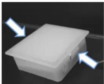
natural_image
White plastic container with two blue arrows pointing inward, no text or symbols visible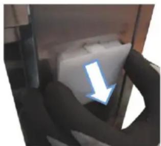
natural_image
Close-up of hands holding a white object with a blue arrow pointing downward (no text or symbols visible)
natural_image
Close-up of a mechanical component with two blue arrows pointing to a square feature (no text or symbols visible)natural_image
3D illustration of a tool interacting with a rectangular object (no text or symbols visible)
natural_image
3D rendered mechanical component with green and yellow parts, no visible text or symbols8.3. ENTRETIEN DES LAMPES
- LED 1.2W, 12vDC, 350mA.
natural_image
Diagram of a multi-tiered electronic device with a small component below (no text or symbols visible)
- LED 4W, 12v AC/DC, GU5.3.
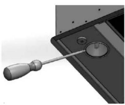
natural_image
Close-up of a screwdriver inserted into a device component, showing a circular dial and handle (no text or symbols visible)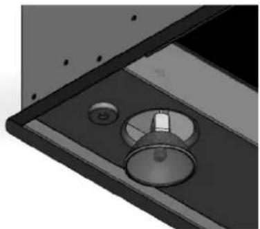
natural_image
Close-up of a mechanical component with a circular knob and mounting holes (no text or symbols visible)- LED 1.3W, 12vDC 110mA
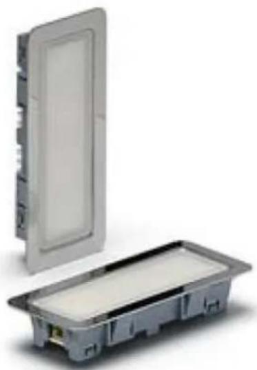
natural_image
Exterior view of a rectangular electronic device with a lid and internal casing (no text or symbols visible)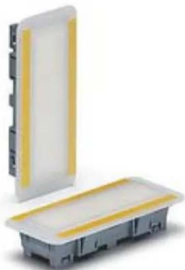
natural_image
Two electronic components: a white rectangular panel with yellow stripe and a gray base with black leads, both without any visible text or symbols.
natural_image
Pure technical line drawing of a mechanical assembly without any text, numbers, or symbols
natural_image
Technical line drawing of a mechanical assembly with no visible text or symbols- SOLUTION DE PROBLÈMES
First of all we wish to thank you for the trust shown on our Company by purchasing one of our products. We are sure you have made the right choice.
In Pando, not only we offer first quality products, but also we make available a large professional team to serve and assist you on any query you may have regarding installation and/or performance.
We also suggest you to pay a visit to our web site (www.pando.es/en) to get to know us better and where you will find all product range containing all necessary commercial and technical information.
A wide selection of extractor hoods can be found there; Wall Hoods, Ceiling, Island or Canopy Hoods. Four types of installation making possible to adapt ourselves to any type of kitchen based on different needs.
At the same time, we take the opportunity to introduce you our collection of in house essential appliances, such our new high performance Ovens and Microwaves, Induction and Gas Hobs to make real your best recipes. Wine Coolers and Aging Wine Coolers to maintain and keep your wines in best of conditions and built-in Dishwashers with latest technology.
All that under a brand with over 40 year history in the market, making products like a real craftsman, and gathering in them the best of our experience to please all your needs.
We sincerely look forward you to have fun, experience and enjoy with the comfort and capacity of what already became your new kitchen ally.
Many Thanks
The PANDO Team
(*) This manual is generic for various models and versions, the use of the certification and mark is only for those whose identification label has indicated the symbol.

The symbol on the product or its packaging indicates that this product cannot be disposed of like normal domestic waste. The product must be handed over at a collection point for recycling electrical and electronic equipment. If you ensure that this product is correctly disposed of, you will help to avoid the possible negative environmental and public health effects that could arise from incorrect disposal. For more detailed information about recycling this product, please contact your city authorities, the domestic waste service or the establishment where you purchased it. This electrical appliance is marked in compliance with European Directive 2012/19/EU on electrical and electronic appliance waste (WEEE).

ENVIRONMENTAL PROTECTION AND WASTE TREATMENT
DISPOSAL OF THE PACKAGING. The packaging is marked with in Green Dot.
In its commitment to the protection of the environment and in compliance with the provisions of the European Directive 94/62 / EC on packaging and packaging waste and the derived Law 22/2011 on Contaminated Residues and Soils, Pando entrusts entities of social economy an Integrated Management System, responsible for the periodic collection at the consumer's home or in its vicinity of used packaging and packaging waste for subsequent treatment.
To remove all packaging materials such as cardboard, expanded polyurethane, and film, use the appropriate containers.
This ensures the correct treatment and reuse of packaging materials.
* Assembly manual supplied with this document, in the documentation bag.
This manual is valid for different models, to determine which parts and functions correspond to your specific hood, CONSULT THE SPECIFIC ASSEMBLY MANUAL FOR YOUR MODEL.
The manufacturer will not be held liable for any possible inaccuracies due to printing or transcription errors in this manual. The manufacturer reserves the right to incorporate modifications considered useful or necessary into the products, which will not alter their essential functional and safety characteristics.
CONTENTS
- SAFETY INSTRUCTIONS....56
- RECOMMENDATIONS TO BEAR IN MIND BEFORE INSTALLATION....60
- INSTALLING AN SEC System conduit (Included only in SEC versions)....64
- ELECTRICAL CONNECTION (Only to be done by qualified professionals)....65
- INSTALLATION OF EXTERIOR, ROOF OR WALL MOTOR (According to versions) ...... 66
- CHARACTERISTICS OF THE EXTRACTION CONDUIT ACCORDING TO MOTOR TYPE..... 68
- INSTRUCTIONS FOR USING THE CONTROLS....69
7.1.ELECTRONIC PANEL 70
7.2. TOUCH CONTROL PANEL 73
7.3.ELECTRONIC DISPLAY PANEL 76
7.4. ELECTRONIC PANEL WITH INTENSIVE 3i....77
7.5.MECHANICAL BUTTON PANEL 78
7.6.SLIDER PANEL 79
7.7. Pando REMOTE CONTROL TOUCH RF 80
- CLEANING AND MAINTENANCE....86
8.1. CLEANING AND MAINTENANCE OF THE HOOD 87
8.2. CLEANING AND MAINTENANCE OF THE FILTERS 89
8.3. MAINTENANCE OF THE LIGHTS 96
- TROUBLSHOOTING 98
- POST-SALES SERVICE (SAT) AND GUARANTEE.... 101
1. SAFETY INSTRUCTIONS
- This appliance can be used by children over the age of 8 as well as physical, sensorial or mentally handicapped people or inexperienced people if they are appropriately supervised or trained regarding the safe usage of the appliance and they are aware of the possible dangers its use could entail.
- Children must not play with the appliance. Any cleaning and maintenance must not be done by unsupervised children.
- If the power cable is damaged it must be replaced by the manufacturer, by the after-sales service or by similar qualified personnel, to avoid hazards.
- If the hood is to be used at the same time as gas fuelled or other fuelled appliances (not applicable to appliances exclusively designed to blow air into the room) the room must be properly ventilated.

- There could be a risk of fire if cleaning is not carried out according to the instructions.
- Do not flambé under the hood.
- WARNING! Accessible parts can get hot when used with boiling appliances.

- The exhausted air must not be led through a conduit that is used for exhausting fumes from other appliances using gas or other fuels (not applicable to devices destined exclusively to discharge the air inside the room).
-The minimum distance between the surface of the cooktop and the lower edge of the hood must be 65 cm if the extractor hood is fitted over gas cooker. If the installation instructions of the gas cooker indicates a greater distance, this must be followed. - Regulations regarding air evacuation must be respected.
- If the hood does not have a power cable with a plug, or other means for disconnection from the mains, with a separation of all poles to ensure total disconnection under category III conditions of overvoltage, means for disconnection of the fixed installation must be incorporated in accordance with installation regulations.
1. SAFETY INSTRUCTIONS
- Respect the frequency of cleaning and filter replacement specified and hood indicated in the maintenance section of the user and installation manual.
- Excessive accumulation of grease could give rise to fires. Never use the hood without the grease filter fitted. See section 8 on hood maintenance, page 86-97.
- Once the appliance has been delivered, within 24h, remove the packaging and check that it is in good state, visually inspecting the general state of the outside. If any anomaly or damage is observed, do not install and immediately inform the dealer or installer within 24h of reception.
- This hood has been designed for normal domestic use. It must not be used for industrial, professional, or any other use different from what it has been designed for.
- Pando will not be held liable for consequences or damages resulting from incorrect installation or misuse of the appliance.
- Do not try to alter any of the characteristics of this appliance, this could be dangerous and will automatically render the guarantee void.
- It must be possible and accessible for the user to disconnect the appliance from the mains after installation. The power plug should be easily accessible, if this is not the case, a switch for electrical disconnection, compliant with electrical installation regulations, must be fitted.
- Take special care when perforating walls or ceilings and ensure that there are no hidden electrical cables, pipes, metal beams, etc., as perforating them could cause great damage, short circuits or the transmission of noise and vibrations.
- IMPORTANT: Before connecting the appliance to the mains, make sure the current is first turned off (differential or circuit breaker on the general electrical panel of the house).
- Hood and conduit installation must comply with regulations on ventilation of closed spaces. More specifically, the exhausted air must not be led through a conduit that is used for exhausting fumes from other appliances using gas or other fuels (central heating installations, etc.).
1. SAFETY INSTRUCTIONS

- Attention! When the hood is in operation “in suction” at the same time as a heating system that depends on ambient air (gas, oil, coal boiler, chimney, etc.), take special care to avoid the hood absorbing air needed for combustion, this could cause dangerous accumulations of carbon monoxide in the premises or home, which could be deadly. If the extractor hood is installed together with a combustion appliance such as a boiler, chimney or local heating, the manufacturers of these appliances must be contacted to ensure optimum and risk-free operation.

- Negative pressure in the premises must not exceed 0.04 mbar. This will allow the hood to operate in optimum conditions. To achieve this, it is necessary to have a permanent entry of fresh air to avoid air stagnation, it is recommended to have a ventilation grille for this purpose. Doors and windows are not enough.
- Electrical power supply must be stable and meet the electrical requirements of the appliance (see the nameplate of the appliance). If the power supply is unstable, with variations in voltage, current, surges and cuts, electrical storms, etc., the hood could malfunction and even be damaged, in which case repairs will not be covered by the guarantee. If any of these things happen, disconnect the hood and contact an electrician or your electrical company to solve the problem.
- To avoid hazards, it is forbidden to manipulate the appliance. If the power cable is damaged it must be replaced by the manufacturer through an authorised technical service. Any repairs that involve manipulating the appliance or its components must only be done by an authorised technical service.
- Improper and unauthorised handling of the hood, as well as modifying, cutting or perforating the body, structure, motor or wiring of the hood are expressly forbidden. In case of any of the above, the guarantee will be automatically void and the manufacturer will not be held liable for any possible harm or d a m ag es .
1. SAFETY INSTRUCTIONS
- The hood is an electrical appliance for fume extraction and must not be used as a support for objects or utensils.
- It is forbidden to cook food directly on the burner flame, or leave the burners without a cooking pot or pan on them, as the flames and heat could be hazardous and could damage the appliance, something that will not be covered by the guarantee. The use of the appliance over wood, coal, charcoal, etc. cookers is not authorised.
- Any frying carried out under the hood must be constantly attended to avoid the oil or fat catching fire.

- WARNING: Always disconnect power to the hood before cleaning or maintenance operations, either by unplugging it or disconnecting with the circuit breaker on the general electrical panel of the house. Never use steam or high pressure devices to clean the hood (electrical safety regulations), see section 8 on cleaning and maintenance.

- The LED lamps can not be manipulated by the user as there are risks of electric shock, handling, maintenance or replacement is a task reserved exclusively for official technical assistance service or authorized specialist installer.
- With the aim of constantly improving our products, we reserve the right to modify their functional characteristics or their appearance.
2. RECOMMENDATIONS TO BEAR IN MIND BEFORE INSTALLATION.
This is a generic manual which is valid for several models. The specific installation guide for your model will be included with this manual in the initial pages or in a separate leaflet included in the accessory bag.
Installation should only be carried out by qualified professionals, professional installers or the official technical service. The manual or installation guide must be read with care before starting the installation process.
When opening the packaging, check that all the components are in perfect state and all the accessories are present. If this is not the case, contact the dealer and do not install. Once installed, any damage to the exterior such as scratches, dents, stains, etc. will not be covered by the guarantee.

VERY IMPORTANT!
DO NOT REMOVE THE PROTECTIVE PLASTIC FROM THE HOOD UNTIL

IT IS COMPLETELY INSTALLED, IF THIS PLASTIC IS NOT PRESENT IN AREAS THAT COULD HAVE A RISK OF DAMAGE DURING INSTALLATION, IT IS RECOMMENDED TO APPLY PROTECTIVE MATERIALS AGAINST IMPACT, SCRATCHES AND CONTACT WITH CORROSIVE AGENTS.
TAKE ESPECIAL CARE DURING THE INSTALLATION IF OTHER WORK IS ALSO IN PROGRESS, BECAUSE PAINT, SILICON, PLASTER AND OTHER MATERIALS COULD CONTAIN CORROSIVE CHEMICALS THAT MAY DAMAGE THE PRODUCT, IN THESE CASES IT IS RECOMMENDED TO ADEQUATELY PROTECT THE HOOD, BY FOR EXAMPLE, HERMETICALLY COVERING AREAS THAT COULD BE AFFECTED WITH PLASTIC.
THIS WILL AVOID DAMAGE TO THE OUTSIDE OF THE APPLIANCE, SOMETHING THAT WILL NOT BE COVERED BY THE GUARANTEE.
It must be taken into account and provide that the hood and peripherals must have easy and safe access for possible maintenance or repair tasks of the official Pando technical service (SAT). The guarantee will NOT cover the costs and means necessary for access to a product that does not meet these conditions. In the event that the product is not easily accessible or safe, a criterion that will be issued by SAT in its initial inspection, it will be the responsibility of the client to place the mean and assume the necessary costs so that the SAT can perform the intervention adequately.
2. RECOMMENDATIONS TO BEAR IN MIND BEFORE INSTALLATION.
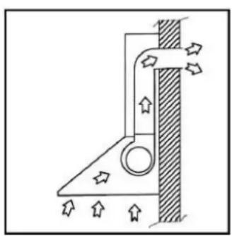
SUCTION VERSION (Fig.1): Expels fumes outdoors, it is the most recommendable, as it offers the best results regarding suction and noise levels.
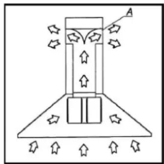
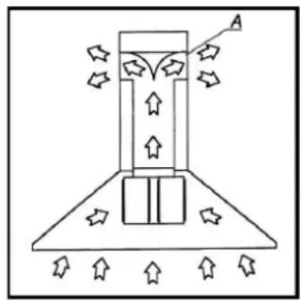
FILTER VERSION (Fig.2) (Optional): Exhausts fumes and smells normally recycled to the inside of the premises (A). This option can be used if it is not possible to exhaust outdoors.
This option offers less suction and produces more noise than the previous.
This filtering option needs a kit of components which includes among, other things, active carbon filters, this kit depending on the version, will be factory fitted, installed by a professional installer or by Pando's authorised technical service. Please consult with the manufacturer or the dealer to see if your model is compatible with this option.
natural_image
Diagram of a mechanical or fluid system with directional arrows indicating flow or movement, no text or symbols present.Fig.1
natural_image
Diagram of a mechanical or fluidic device with directional arrows and a labeled point A, no readable text or symbols present.Fig.2
Pay special attention to all the instructions given below, as optimum operation of you hood will depend on this.
• CONDUIT FOR EVACUATING FUMES AND SMELLS:
A. With a diameter as recommended in the installation manual and the technical datasheet of the version of the motor (see section 6 of the manual).
B. Try to make it as short as possible and avoid or limit the number of bends, if they are unavoidable, try to make them as open as possible, never make bends of less than 90^ .
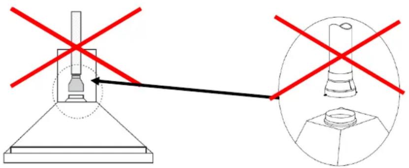
C. Avoid changes in shape and section of the conduit outside the manufacturer's recommendations, as this will drastically affect the optimum operation of the hood.
(a) If it is necessary to use a conduit smaller than the recommended section, the motor will offer less suction and noise levels will increase. A tip for minimising losses is not to place the narrowing at the outlet of the motor, but at least 0.5-1 m away, leaving this first part at least with an adequate section.
2. RECOMMENDATIONS TO BEAR IN MIND BEFORE INSTALLATION.
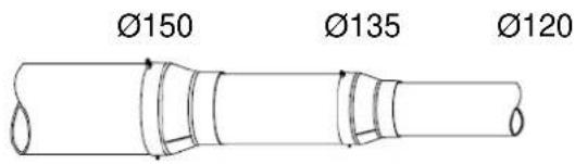
(b) If the undesirable reduction is very significant, do not do it suddenly, but rather make partial reductions, for example, from 150mm to 120mm , first reduce from 150 to 135 , use a straight section 0.5-1m long of 135 and then apply a second reduction from 135 to 120mm .
(c) Do not place curves or bends just before or after a reduction.
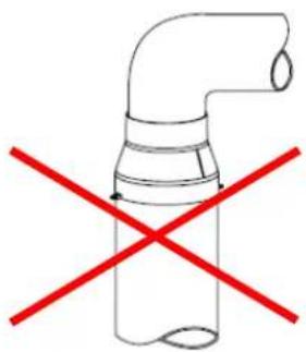
D. It is recommended to use conduits with minimum losses due to friction, therefore the walls should be as smooth as possible, in the case of flexible conduits, stretch them out well so the corrugated walls are as smooth as possible, this will improve suction as well as reduce noise levels.
E. The outlet to the exterior must not be blocked by elements that could reduce its natural section or obstruct the outlet. When connecting to a common flue, the outlet must be as indicated in the illustrations.
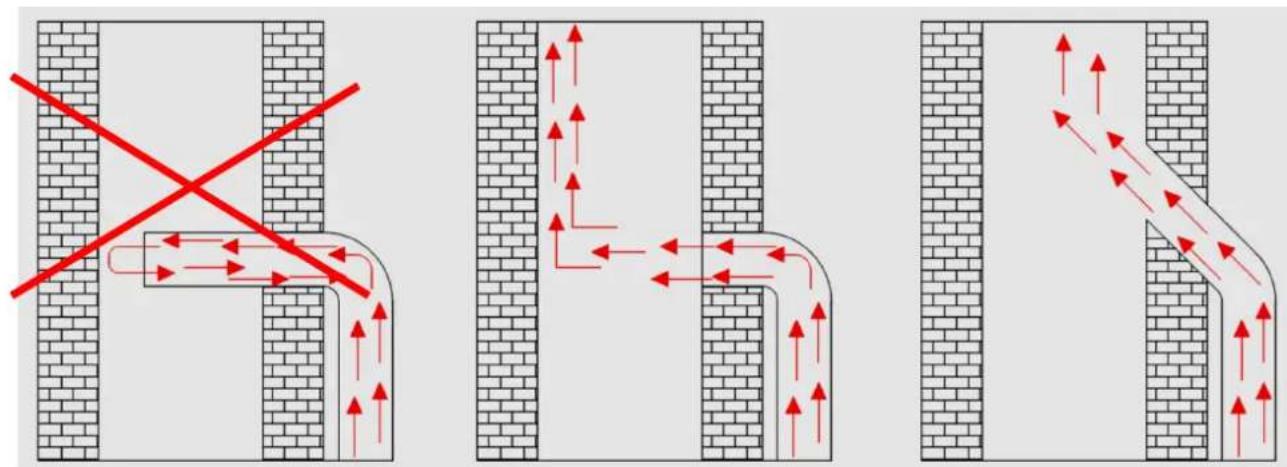
INCORRECT CORRECT BETTER
F. Air exit to the interior with filter systems must not be blocked, leaving a minimum gap of 20 cm from any obstacle such as a wall or ceiling.
G. Use conduits of adequate composition for the intended use, compliant with regulations.
2. RECOMMENDATIONS TO BEAR IN MIND BEFORE INSTALLATION.
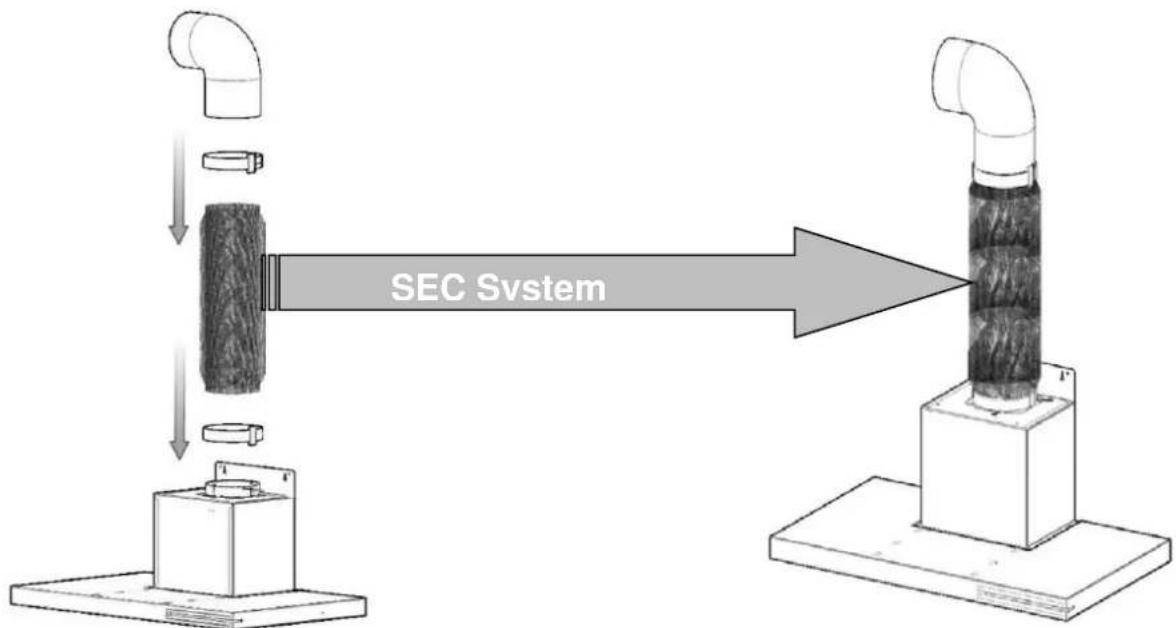
H. For a soundproofed installation, we recommend using our special S.E.C. System tubing for fume evacuation conduits. Ask your dealer.
natural_image
Close-up of a textured, elongated object with no visible text or symbols
• THE RIGHT SIZE AND DISTANCES:
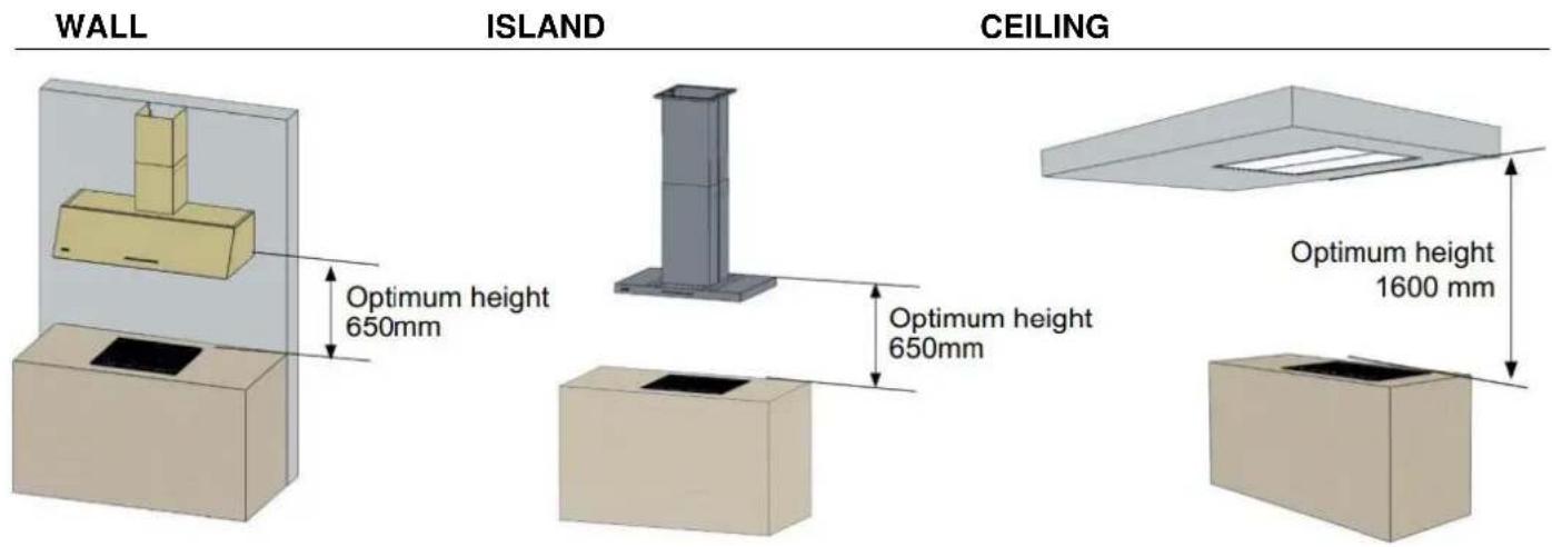
a) HWIGHT OF THE HOOD: For hood installations over a gas cooker, the minimum height between the cooktop and the bottom of the hood should be 65 cm according to regulations. The distance can be greater, according to the type of cooktop, consult the manufacturer or the manual of the cooktop. A greater distance than the recommended could cause less than optimum operation as fumes may leak from the sides. Consult the installation manual, which will indicate the height of the hood over a gas cooker. A very small distance could worsen the condensation effect, especially in the case of induction
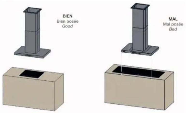
b) WIDTH OF THE HOOD: The hood must always be wider than the cooking area (except in some special models). If it is narrower, you run the risk of fumes escaping from the ends.
c) C CENTRING OF THE HOOD: The hood will be placed in such a manner that its filters are centred over the cooking area.
d) VENTILATION ENTILATION AND DRAUGHTS: All hood installations need a continuous air inlet with a diameter at least equal to the outlet diameter of the motor, preferably opposite the hood and care should be taken with other air inlets that could give rise to draughts that would reduce suction power. No air inlet will cause problems of depression and atmospheric over-pressure making the hood motor perform badly and significantly affecting suction performance.
CONDUIT ACCESSORIES (Optional).
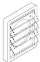
OUTSIDE CONDUIT OUTLET (Not included): The outlet to the outside should have a hatch opening by air pressure. Under no circumstances use gas grilles or others that could obstruct the free movement of air. Neither should the exit to the outside be left uncovered, as this could give rise to the entrance of foreign objects (water, strong wind, bird's nests...) that could obstruct the airflow and damage the hood.
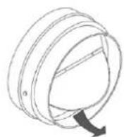
ONE-WAY VALVE (Not included): Only recommended for use in community installations, where several conduits join into one, to avoid fume blowback and the entry of fumes and smells from other hoods, etc. Take into account that these devices need maintenance by authorised professionals.
3. INSTALLING AN SEC System conduit (Included only in SEC versions)

NEVER FIT AN SEC System TUBE AS A COVER OR OVER A SMALLER DIAMETER TUBE IN THE PRE-INSTALLATION OF THE PREMISES.

flowchart
graph TD
    A["Pipe"] --> B["Tube"]
    B --> C["Vertical Tube"]
    style A fill:#f9f,stroke:#333
    style B fill:#ccf,stroke:#333
    style C fill:#cfc,stroke:#333
    subgraph SEC System
        direction LR
        B -->|Downward arrow| A
        B -->|Upward arrow| A
    end
4. ELECTRICAL CONNECTION (Only to be done by qualified professionals)
The power for the cable that you must use with the hood must be single phase, Neutral, Line and Earth, 220-240vAC 50-60Hz.

ATTENTION! During installation and subsequently, when carrying out any operation inside the hood or during maintenance, make sure the appliance is disconnected from the mains.

The electrical power supply must be stable and meeting the electrical requirements of the appliance (see the nameplate of the appliance).
The hood must be connected to the mains supply with an independent line to the electric panel so as to avoid interference in the hood caused by fluorescent lamps or other devices that transmit noise to the mains.
Make sure the mains plug of the appliance is accessible or if not, install a switch in compliance with electrical regulations.
If the hood does not have a power cable with a plug, or other means to disconnect it from the mains with a separation between the poles, and with means to disconnect completely under category III overvoltage conditions, it must be fitted with means to disconnect it from the mains in case of category III overvoltage conditions (Multi-pole disconnection switch connected directly to the power terminals, with a separation between the poles to interrupt electrical supply in the case of category III overvoltage).
If the power cable is damaged, it must be replaced by the manufacturer, your after-sales service or qualified personnel, to avoid hazards.
Make sure you do not disconnect or cut any wires inside the hood, if this were to happen, contact the nearest after-sales service. Request the aid of a qualified technician for electrical connection.
This must be done in compliance with current regulations.
If the specifications label inside the hood displays this symbol ☐ the appliance is class II. In which case it does not need an earth connection.
If the specifications label inside the hood DOES NOT display this symbol ☐ the appliance is class I. In this case it NEEDS an earth connection.
The cable connecting the hood and the motor in “Exterior Motor” models should have a minimum section of 3 x 1 mm.
The cable connecting the hood and the motor in “Roof Motor” models will be of HO7RN-F class and characteristics with a 3 x 1mm section (up to 5 metres in length.) and 3 x 2.5 mm (up to 25 metres in length).
The extractor hood must “always” be connected to an installation with a good “earth”. Pando will accept no responsibility if these instructions are not followed (except in Class II appliances, indicated with this symbol ☐).
Key for power cables:
1: Brown or black = Line / Phase(L)
2: Blue = Neutral (N)
3: Green / Yellow = Earth
220-240V 1N\~

5. INSTALLATION OF EXTERIOR, ROOF OR WALL MOTOR (According to versions)
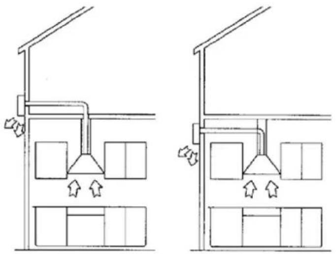
Each of these motors have their own complete installation manual in the packaging, inside the accessory bag. Below you will find graphic details for part of the fitting. For installing them, always consult their specific installation manual.
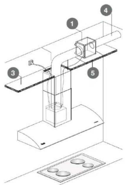
VERY IMPORTANT: The motor (exterior version false ceiling, roof or wall), must be “accessible and safe” for Technical Assistance Service personnel. There must be easy access to the motor for maintenance or possible repairs. If the location of the motor poses a hazard for people or lacks an accessible hatch, Pando reserves the right to refuse to do the work until this is remedied Therefore, please take this into account to avoid future maintenance problems.
Cables and connections coming out of the motor and the hood must not be cut or modified, if any action of this type is observed, the guarantee will automatically be void.
5.1. FALSE CEILING EXTERIOR MOTOR:
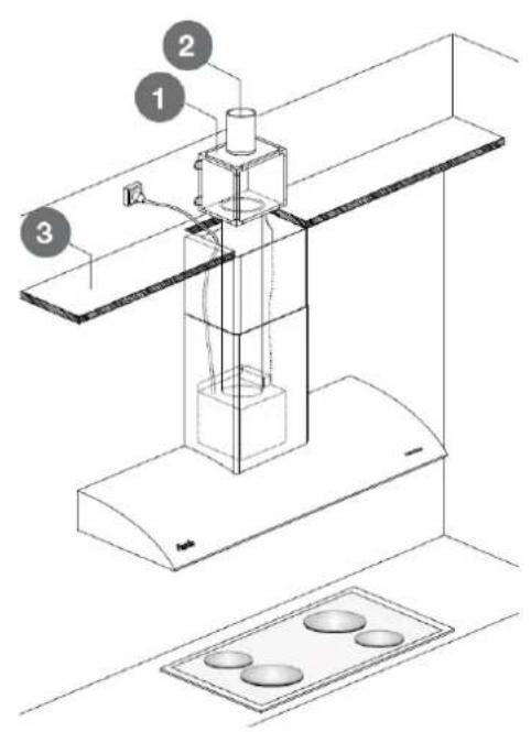
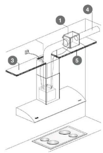

Motor

False ceiling

Registry for accessing the motor (Very important, it must be easy to access and of the sufficient size to be able to remove the motor)

me outlet directly to the outside
The exterior false ceiling motor is not designed to be placed outside the house, in the open, this could give rise to damage not covered by the guarantee.
5. INSTALLATION OF EXTERIOR, ROOF OR WALL MOTOR (According to versions)
5.2 ROOF EXTERIOR MOTOR:
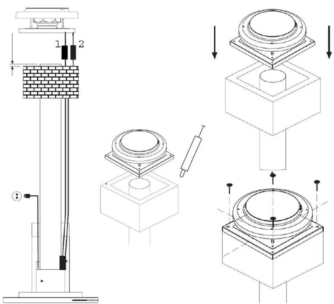
5.3. FACADE WALL MOTOR:

natural_image
Two technical line drawings of a building interior with ventilation ducts and storage compartments (no text or symbols)6. CHARACTERISTICS OF THE EXTRACTION CONDUIT ACCORDING TO MOTOR TYPE
NOTES:
| MOTOR VERSIONS | MOTOR TYPE | ∅Conduit | POWER | Maximum recommended length of conduit | Length of motor connection cables |
| W MAX.W | Linear meters | ||||
| INTERIORS motors (inside the hood) | |||||
| V700 | 120 / 150INT | 140 | 4 | - | |
| V730 | 120INT | 125 | 5 | - | |
| V750 | 125INT | 150 | 6 | - | |
| V850 | 150INT | 265 | 8 | - | |
| V950 | 150INT | 350 | 6 | - | |
| V1350 | 150INT/EXT | 290 | 10 | - | |
| INTERIOR motors (inside the hood) | |||||
| V1130 ECO | 150INT | 85 | 8 | - | |
| V1050 ECO SEC PLUS | 150INT | 170 | 8 | - | |
| V1250 ECO | 150INT | 230 | 10 | - | |
| V1350 ECO | 150INT/EXT | 230 | 10 | - | |
| V2200 ECO | INT | 200 | 750 | 15 | - |
| ECO INTERIOR motors (inside the hood) | |||||
| V1200 TIPO 1 | EXT | 150 | 350 | 6 *a | 7 |
| V2000 TIPO 1 | EXT | 200 | 250 | 10 *b | 7 |
| ECO EXTERIOR motors | |||||
| V1550 ECO TIPO 1 Y 2 | EXT | 150 | 230 | 10 *c | 6 |
| V2450 ECO TIPO 2 | EXT | 200 | 168 | 12 *d | 6 |
| V2600 ECO TIPO 1 Y 2 | EXT | 200 | 750 | 15 *e | 12 |
| V3000 ECO TIPO 2 | EXT | 200 | 660 | 18 *e | 12 |
| ECO OUTDOORS WALL MOTOR | |||||
| V1300 ECO | MUR | 150 | 168 | 6 | 6 |
| ECO ROOF motors (on roof or chimney) | |||||
| V2350 ECO | TEJ | 200 | 168 | 12 *f | 12 |
| V3300 ECO | TEJ | 200 | 660 | 18 *g | 18 |
Limit the number of curves in the conduit, as each curve reduces suction efficacy:
- In ∅150 mm one 90° bend = 1m linear.
- In ∅200 mm one 90° bend = 2.5m linear.
Example: If two 90^ bends are used, the total length of a conduit of 3m linear 150mm (3+1+1), is 5m.
Example: If two 90^ bends are used, the total length of a conduit of 3m linear 200 mm (3+2.5+2.5), is 8m. The values indicated derive from tests conducted in laboratory conditions. Depending on the model and characteristics of each hood, they could vary significantly.
Due to constant improvements made by Pando to their products, the latest update to this information can be found on our website (www.pando.es).
The technical specifications datasheet of your hood and the energy classification label can be found in the documentation contained in the accessory bag.
*a. From hood to motor max. 2m
*b. From hood to motor max.2m - max. 6m
*c. From hood to motor min. 4m
*d. From hood to motor min. 4m- max. 6m
*e. From hood to motor max. 6m - max. 12m
*f. From hood to motor min. 4m - max. 12m
*g. From hood to motor min. 6m- max. 18m
*h. Exterior motor available according to model,consult catalog.
7. INSTRUCTIONS FOR USING THE CONTROLS.
It is advisable to switch on the hood shortly before starting to cook and leave it on for a while after finishing, to evacuate all the fumes and smells from the premises and the conduit.
Further below all details regarding common special functions in all Pando controls can be found, and further down all user's guidance on each control model by Pando.
TIMER "Ecodesign"
* (REGLATION UE N° 66/2014 DISEÑO ECOLÓGICO)
As of 1 January 2015, with the entry into force of the new European Commission regulation EU65 “Energy label” and EU66 “Ecodesign”, we have adapted our products to the requirements of these regulations.
All the “Energy label” version models have an electronic timer to limit the time of suction speeds exceeding 650m^3/h .
In compliance with this energy saving regulation, when the hood is turned on at maximum or medium speed (depending on the motor version) and it exceeds 650m^3/h , after 6 or 7 minutes (depending on the motor version) the hood will automatically switch down to a lower speed. To return to the higher speed, press the increase speed key again and the timer will begin to count from 0 minutes.
SPECIAL FUNCTIONS (Pando LED-AIR Clean)
Depending on the model and version of your extractor hood some functions are standard in the product, whilst in others is optional and some might not be compatible. You can check functions of your model in the catalogue, in our web site, in the rating product label or by contacting with Pando.
Pando LED (Function only for models with Pando LED logo on their internal label)
LED lighting system adjustable in brightness or intensity (*dimmable), as well as lighting temperature (tunable).

Latest generation state-of-the-art lighting allows creating multiple different atmospheres, offering a wide range of colour spectrum between warm and cold. This is the reference type of lighting in Pando products.
The electronic dimmer adjusts the energy supplied to the LED lamp so that the lighting emitted intensity can be set up. The brightness can therefore be adapted at will anytime, from intensive working mode to a light ambient mode, saving energy consumption at the same time.
* Models coming with courtesy lighting are not compatible with the Dimmable function or brightness adjustment: in these models only the °K temperature colour can be adjusted.
7.1. ELECTRONIC PANEL

flowchart
graph LR
    A["Start"] --> B["Drop"]
    B --> C["Power"]
    C --> D["Triangle"]
    D --> E["End"]
 | MAIN OR WORKING LIGHT: Press to switch on main lights and press again to switch off. When the lights are on the key is brightly lit.COURTESY OR AMBIENT LIGHT: (Optionally, depending on model and version) Keeping the key pressed for 2 seconds will switch on the courtesy light, and continuing pressing will switch it off again. |
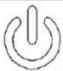 | ON / OFF: Press to switch on the motor and the key will light up brightly and steadily, press again to switch off the motor and the key dims. |
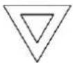 | (-): Press to lower motor speed. When at minimum speed the key will flash brightly. |
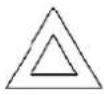 | (+): Press to increase motor speed. When at maximum speed the key will flash brightly (*see Ecodesign timer section p.69). |
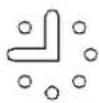 | LAST TIME: Press to activate the timer the Last Time key lights up brightly and switch on the motor at maximum speed for 5 minutes. Once on, it can be adjusted to a lower speed if you wish. When the time has elapsed, the motor stops and the hood lights turn off. The Last Time key will light up brightly. |

FILTER SATURATION WARNING (30h).
The hood has an automatic filter saturation warning system that works by a timer which will broadcast a warning when it is necessary to do a filter cleaning.
After 30 hours of operation, all buttons of electronic panel will light up and flash. If you press any button, they will stop flashing and the counter will restart.

S.I.A. Safety - AUTOMATIC SAFETY DISCONNECTION (5h)
The hood has an automatic disconnection system to avoid it staying on for excessively long periods of time.
Once the hood is switched on, if no button on the panel or the remote has been pressed in 5 hours, the hood will automatically switch off the motor and lights.
7. 1.1. Pando LED. Setting Mode with electronic panel.
With this button control 11 different temperature (°K) – colour-adjustment levels are available, and in addition 10 different bright/intensity levels. Once the desired mode is changed, this last set will be maintaining.
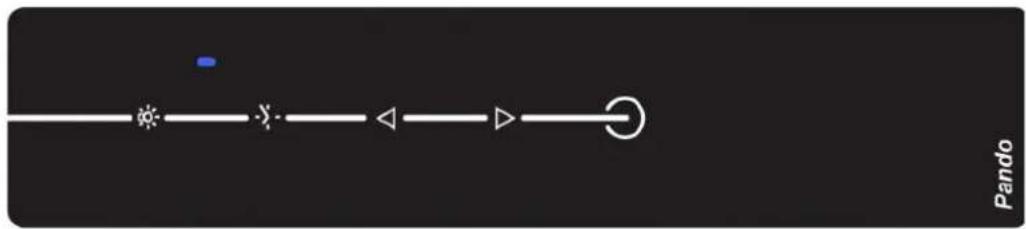
- Setting Mode With the hood off, keep press "Light" button for at least 3 seconds, then buttons "Up/Down" will shine and lighting button will flicker. This mode is active while we keep pressing different adjustments.

- Brightness / Intensity settings. With the setting mode on, try short and paused pushes on button "Down"; with it the brightness can be set up to 10 different tones between 10 and 100% . Going from low to high, should a lower tone be needed then the cycle needs to be finish to start over.
| 10......100% | |
- Colour and/or temperature settings °K. On set mode on, give short and paused pushes on button "Up", allowing colour change up to 11 different tones between 2700°K and 6000°K, or 2700°K and 4000°K depending on the LED version. Going from low to high, should a lower tone be needed then the cycle needs to be finish first to start over.
| 2700......6000°k 2700......4000°k | |
| tunable |
Setting Mode Off. After 15 seconds without pressing any button, the setting mode is automatically turned off, "Down / Up" buttons switch off and lighting remains on with latest adjustment set.
7. 1.2. Pando AIR Clean with electronic panel.
Automatic Motor Function System.

flowchart
graph LR
    A["Start"] --> B["Drop"]
    B --> C["Power"]
    C --> D["Triangle"]
    D --> E["End"]
Automatic function renewing the air on minimum energy consumption and maximum comfort. Motor is set on for 10 minutes every hour on first speed and during a cycle of 5 hours. By doing this the air in the room is renewed on low sound level automatically.
- PANDO AIR Clean set on mode. With the hood off, keep press "Timing" button during 3 seconds, then as mode on set, button ON/OFF will flicker, and motor will start on minimum speed, being automatically set for a 5 hours cycle on 10 minutes mode each hour.
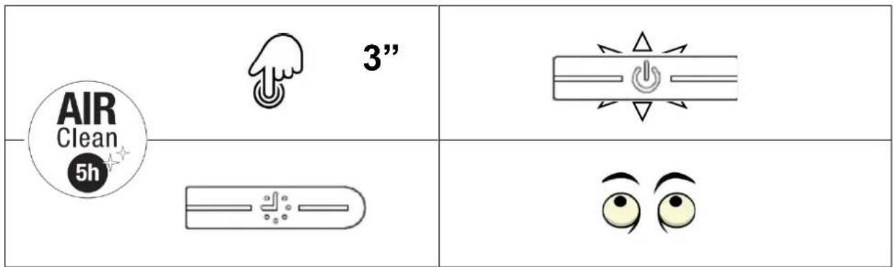
- PANDO AIR CLEAN set off mode. After the 5 hours program, the motor goes completely to a halt and does not start up again. Should we need to set off the function before finishing the 5-hour cycle press "ON/OFF". With this function on, lighting can be on/off, but does not admit motor speed setting.
 |  | SHORT PRESSION (briefly and firmly for 1 second):Motor ON at first speed. |
 | LONG PRESSION (keep a few seconds):OFF, engine off = Press the symbol extensively and firmly for about 3 seconds. | |
 |  | SHORT PRESSION: Motor at second speed. |
 |  | SHORT PRESSION: Motor at third speed. |
 | LONG PRESSION (keep a few seconds): intensive speed(4a). | |
 |  | TIMER. Push this button to set up the timer of 5 minutes. After 5 minutes the cookerhood will be switched off automatically (motor and lighting). When the timer is activated the LED flashes.The timer can not be activated for intensive speed "i"(4a). |
 |  | Push This button to switch on/offthe light. |

SATURATION FILTER ALARM:
- FOR METALIC FILTERS (Lighting symbol lickers):
Every 30 hours, the hood light button will start flickering, meaning the grease filters need to be washed. To reset the time counter, press "light" button during 3 seconds with the hood off.
- FOR REACTIVABLE CARBON FILTERS (FCA/ FCLR AE):
Every 120 working hours, the button “on/off” will flicker, meaning it is necessary to replace it or clean the FCA/FCLR AE filter set (for recirculation version).
To reset the 120 hours counter, with the hood off, press the "light" button during 3 seconds
For proper operation, keep the Touch Control glass clean and dry. If there is dirt on the Touch Control glass it may fail or not respond adequately to the commands.
7. 2.1. Pando LED. Setting mode with touch invisible control panel.
With this type of button control, 10 different setting levels on temperature ( ^9 K) or colour, as well as 10 different settings on brightness or intensity are available. Once set on the desired level, this will be memorized.
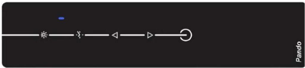
- Adjustment Setting mode: With the hood off, keep press "Light" button for at least 3 seconds, then buttons "On/Off and 3i" will shine and lighting button will flicker. This mode is active while we keep pressing different adjustments.
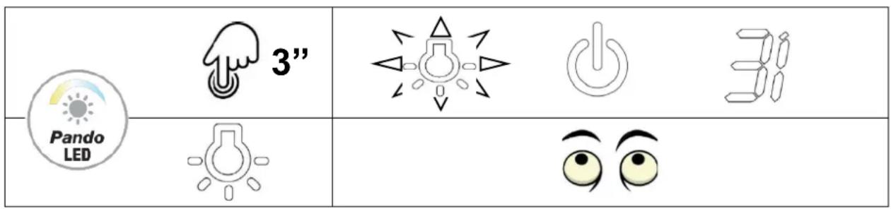
- Brightness / Intensity adjustment: With the setting mode on, try short and paused pushes on button "On/Off"; with it the brightness can be set up to 10 different tones between 10 and 100%. Going from low to high, should a lower tone be needed then the cycle needs to be finish to start over.
| 10......100% | |
| dimmable |
- Colour and/or temperature settings °K. On set mode on, give short and paused pushes on button "3i", with it colour is changed up to 10 different tones between 2700°K and 6000°K, or 2700°K and 4000°K depending on the LED version. Going from low to high, should a lower tone be needed then the cycle needs to be finish to start over.
| 2700......6000°k 2700......4000°k | |
| tunable | |
| 31 |
- Setting Mode Off. After 15 seconds without pressing any button, the setting mode is automatically turned off, "ON/OFF and 3i" buttons switch off and lighting remains on with latest adjustment set.
7.2.2. Pando AIR Clean mode with touch invisible control panel.
Automatic Function Motor System.

Automatic function renewing the air on minimum energy consumption and maximum comfort. Motor is set on for 10 minutes every hour on first speed and during a cycle of 5 hours. By doing this the air in the room is renewed on low sound level automatically.
- PANDO AIR Clean set on mode. With the hood off, keep press "Timing" button during 3 seconds, then as mode on set, button ON/OFF will flicker, and motor will start on minimum speed, being automatically set for a 5 hours cycle on 10 minutes mode each hour.
 |  |  |
 |  |
- PANDO AIR CLEAN set off mode. After the 5 hours program, the motor goes completely to a halt and does not start up again. Should we need to set off the function before finishing the 5 hour cycle press "ON/OFF". With this function on, lighting can be on/off, but does not admit motor speed setting.

S.I.A. Safety - AUTOMATIC SAFETY DISCONNECTION (5h)
The hood has an automatic disconnection system to avoid it staying on for excessively long periods of time.
Once the hood is switched on, if no button on the panel or the remote has been pressed in 5 hours, the hood will automatically switch off the motor and lights.
7.3. ELECTRONIC DISPLAY PANEL


ON/ OFF, press this button to start the motin 2 ^nd speed, press again to stop it.
Press the button to reduce the speed of the motor.
Display that indicates the speed member of the motor.
Press the button to increase the speed of the motor. At top speed Booster (3), the display will show a flashing spot indicating that you are in Ecodesign function, and this speed will be timed to 7 minutes before returning to the 2nd speed (*see section Ecodesign Timer Page 69).
TIMER: Pressing this button when the motor is in operation will activate the timer and the display will flash, after 5 minutes the motor will turn off. Once on, the speed can be adjusted as you wish.
Press this button to turn on the lights, press again to turn off.
IR receiver for the optional remote control. (See point 7.7)
7.4. ELECTRONIC PANEL WITH INTENSIVE 3i
 |  | SHORT PRESSION (briefly and firmly for 1 second):Motor ON at first speed. |
 | LONG PRESSION (keep a few seconds):OFF, engine off = Press the symbol extensively and firmly for about 3 seconds. | |
 | SHORT PRESSION: Motor at second speed. | |
 | SHORT PRESSION: Motor at third speed. | |
| LONG PRESSION (keep a few seconds): intensive speed(4a) for 7' (at the end of this time, the system will return to the speed set previously). | ||
 | TIMER. Push this button to set up the timer of 5 minutes. After 5 minutes th cookerhood will be switched off automatically (motor and lighting). When the timer is activated the LED flashes.The timer can not be activated for intensive speed "i"(4a). | |
 | Push This button to switch on/offthe light. | |
MAINTENANCE FUNCTIONS:
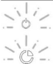
- CLEAN AIR:
natural_image
Two simple icons: a power button and a circular refresh symbol, both radiating from each other (no text or labels)To preserve air quality--> push Timer button Ⓗ for 3" with hood off. The hood turns on at first speed
for 10' per hour, while the function is activated, the power and timer symbols flash.
Push any button to disable the function except the lighting button
• FILTER SATURATION ALARM:
- MESH FILTERS:

Light button LED flashes every 30h of hood operation: the anti-grease filter shall be cleaned.
To reset the hood when it is off push light button for 3".
- ACTIVE CARBON FILTERS (FCA):
On/off button LED flashes every 120h of hood operation: the anti-odor filter shall be replaced (FCA) (filter version).
To reset the hood when it is off push light button for 3".
For proper operation, keep the Touch Control glass clean and dry. If there is dirt on the Touch Control glass, it may fail or not respond adequately to the commands.
7.5. MECHANICAL BUTTON PANEL

 | Switch for turning light on (1) and off (0) | Switch for turning the motor on (1) and off (0).3 speed selector: (1). Minimum speed(2). Medium speed(3). Maximum speed (1). Minimum speed(2). Medium speed(3). Maximum speed |

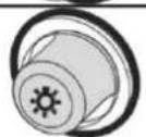
Pilot light indicating motor on.
Motor switch off button.
Button for turning in the motor in first or minimum speed.
Second or medium motor speed button.
Third or maximum motor speed button.
Lights on/off button.
7.6. SLIDER PANEL

| Button | Function | Remarks |
 | Turns the Motor ON. | When is off. |
| Enable shutdown the Motor with a 3 minutes delay meanwhile flashes. | When is on. | |
| Turns the Motor OFF. | When is flashing. | |
 | Turns the Motor on at speed Low. | Buttons are on. |
 | Turns the Motor on at speed Medium. | Buttons are on. |
 | Turns the Motor on at speed High. | Buttons are on. |
 | Turns the Motor on at speed BOOST. | Buttons are on. |
| [HS4S] | In the state of shutdown, this lamp is not bright | The up and down slipping can adjust air volume. |
 | Turns the Lighting System on and off at maximum intensity. | Button on. |
 | Run automatically 10 minutes per hour. | When is off and is on. |
7.7. Pando REMOTE CONTROL TOUCH RF
flowchart
graph LR
    A["Start"] --> B{Decision}
    B -->|Yes| C["End"]
    B -->|No| D["End"]
 | ON/OFF, Press this symbol to turn on the motor, press again to turn off. |
 | Press this symbol to lower the motor speed. |
 | Press this symbol to increase motor speed, Note: If you have a motor version that exceeds 650m3/h, 3rd or 4th speed will be timed. (*see Ecodesign Timer section, Page 69). |
 | LAST TIME: When the motor is on at any speed, pressing this button will start a 5-minute timer, at the end of which time the motor and lights will switch off. When on, it is possible to adjust the speed to the desired level. This function is indicated on the display by flashing dots. This function offers a visual indicator by flashing the pilot lamp. |
 | MAIN OR WORKING LIGHT: Press to switch on main lights and press again to switch off. COURTESY OR AMBIENT LIGHT: (Optionally, depending on model and version) Keeping the key pressed for 2 seconds will switch on the courtesy light, and continuing pressing will switch it off again. |
 | Blue LED that will light up whenever a function is pressed. |
| Control Hood button Colour Tones: (Only for Ceiling Hoods). | |||
 | White | ON and 1st speed | |
 | Light Blue | Motor on 2nd speed | |
 | Dark Blue | Motor on 3rd speed | |
 | Reed | Motor on 4th speed (maximum sped) | |
 | Yellow | Pando LED settings. (Only models with Pando LED) | |
7.7.1. Pando LED setting mode with remote control TOUCH RF.
With this button control 11 different temperature (°K) – colour-adjustment levels are available, and in addition 10 different bright/intensity levels. Once the desired mode is changed, this last set will be maintain.
- Setting Mode With the hood off, keep press "Light" button for at least 3 seconds, then pilot led light will shine yellow flickering. This mode is active while we keep pressing different adjustments.
 |  |  | Yellow |
 |  |
- Brightness / Intensity settings. With the setting mode on, try short and paused pushes on button "Down"; with it the brightness can be set up to 10 different tones between 10 and 100%. Going from low to high, should a lower tone be needed then the cycle needs to be finish to start over.
 |  | 10......100% |
 |  |
- Colour and/or temperature settings °K. On set mode on, give short and paused pushes on button "Up", with it colour is changed up to 11 different tones between 2700°K and 6000°K, or 2700°K and 4000°K depending on the LED version. Going from low to high, should a lower tone be needed then the cycle needs to be finish to start over.
 |  | 2700......6000°k2700......4000°k |
 |  |
- Setting Mode Off. After 15 seconds without pressing any button, the setting mode is automatically turned off, "Down / Up" buttons switch off and lighting remains on with latest adjustment set.
7.7.2. Pando AIR Clean with remote control TOUCH RF.
Automatic Function Motor System
flowchart
graph LR
    A["Start"] --> B["Node 1"]
    B --> C["Node 2"]
    C --> D["Node 3"]
    D --> E["Node 4"]
    E --> F["End"]
    style A fill:#fff,stroke:#000
    style F fill:#fff,stroke:#000
    classDef default stroke-dasharray: 5 5;
    class A,B,C,D,E default;
Automatic function renewing the air on minimum energy consumption and maximum comfort. Motor is set on for 10 minutes every hour on first speed and during a cycle of 5 hours. By doing this the air in the room is renewed on low sound level and automatically.
- PANDO AIR Clean set on mode. With the hood off, keep press "Timing" button during 3 seconds, then as mode on set, pilot led light button will flicker in white, and motor will start on minimum speed, being automatically set for a 5 hours cycle on 10 minutes mode each hour.
 | 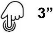 |  | White |
 |  |
- PANDO AIR CLEAN set off mode. After the 5 hours program, the motor goes completely to a halt and does not start up again. Should we need to set off the function before finishing the 5 hour cycle press "ON/OFF". With this function on, lighting can be on/off, but does not admit motor speed setting.

SATURATION OF FILTERS IN PILOT-BEEP AERIAL MODULE
The hood has a filter saturation warning system, which works through a 30-hour timer, which will emit a visual colours signal warning that it is necessary to clean the filters.
After 30 hours of operation of the hood, when it is turned off, a warning signal will be displayed on the LED, this visual signal is a cycle of colour change every second in the following sequence: white, light blue, dark blue, red, dark blue, light blue and white ....
To switch off the warning and reset the hour counter to zero, pressing the engine or lights start button is reset.
7.7.3. Pando multicolour pilot light without button panel
HOODS WITHOUT BUTTON PANEL – ACOUSTIC AND VISUAL CONFIRMATION MODUL:
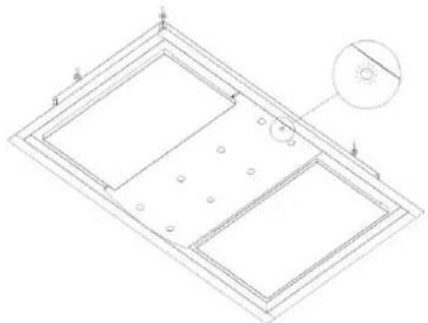
natural_image
Technical line drawing of a rectangular frame with internal compartments and mounting holes, no text or symbols presentCeiling E-250 sample drawing on multiple colour pilot mode. Depending on hood model the pilot led can be found in different positions being the lighting emitted sign always visible.
ON/OFF SAFETY BUTTON, OPTIONAL DEPENDING ON HOOD MODEL AND VERSION
Some ceiling hoods and a few ones wall mounted, built in or island type, without visible button control, are controlled via remote PANDO TOUCH RF, in which cases the hood will come with an emergency switch placed below filters.
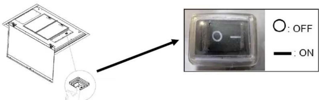
ACOUSTIC CONFIRMATION DEVICE (BEEP)
Any order transmission using the remote control is confirmed by a short “beep” when a function is selected (Optional available or compatible based on the model and version, associated or not to the speed visual confirmation).
WALL MOUNTED BUTTON CONTROL SWITCH (Option upon request.)
A ceiling hood can be controlled via independent Wall Button panel Switch up to 10 m. away from the hood. When installing this Control switch, the pilot led control mode/beep will be set off. Yet, Remote Control TOUCH RF will also work but with no visual or acoustic sign in the hood. Control functions will be shown on the electronic control mounted panel.
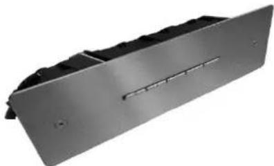
natural_image
Metallic rectangular device with internal compartments and a slot, shown against a white background (no text or symbols visible)Note: On motor versions over 650 m3/h, 3rd and 4th speed will be time limited. (* see Ecodesign Timer Section p.69).
7.7.4. Adjustment and Calibration remote control TOUCH RF.
A - SYNCHRONIZATION REMOTE CONTROL (\* only if necessary, it is already synchronized):
- Connect the hood to the mains or turn on the hood switch, optional under filters or panel.
- ATTENTION!: once step 2 is completed, when connecting the hood to the electricity:

DO NOT TOUCH ANY COMMAND KEY UNTIL AFTER 5 SECONDS

- After the first 5 seconds, in the interval time between 5 and 20 seconds, with the remote control facing the hood, press or hold the LIGHT button ☑ on the remote control, and the lights on the hood will light up, confirming that the process has been successfully performed.
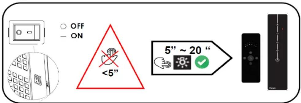
If it takes more than 20 seconds to synchronize the control, the hood switchboard closes the reception and does not record any code, you must repeat the process, making sure to press the key between 5 "and 20".
B - SYNCHRONIZATION REMOTE CONTROL (* only if necessary, it is already synchronized):
The manufacturer supplies the remote control ready for use, with the codes predefined in the factory.
It is not necessary to change or sync the code, except if, due to external reasons the hood does not work (*loss of the code due to mains fluctuations, low battery power in the remote control or unintended operation caused by interference in the frequency by another user).
If you want generate new codes, perform the following process:
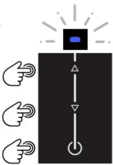
Press simultaneously and keep pressed the three keys indicated in the illustration by arrows, until the blue LED on the remote control begins to flash, at this moment the remote is scan of the different codes, when you release the keys, the LED will stop flashing and record the code that was being scanned at that moment, in this manner the control code will be different to the original one.
Warning! Once this process has been carried out, the control will not communicate with the hood, because on changing the code in the control, it will be different from the one the hood had before. For it to work again, you must resynchronise the control, see section “A”.
If you wish to use another code, repeat the process (after establishing the factory configuration) and the selected code will depend on the time you keep the keys pressed.
7.7.4. Adjustment and Calibration remote control TOUCH RF.

S.I.A. Safety - AUTOMATIC SAFETY DISCONNECTION (5h)
The hood has an automatic disconnection system to avoid it staying on for excessively long periods of time.
Once the hood is switched on, if no button on the panel or the remote has been pressed in 5 hours, the hood will automatically switch off the motor and lights.
MAINTENANCE
It is recommended to replace the battery at least once a year or whenever the control begins to show communication problems. To replace an exhausted battery, use a screwdriver to remove the battery cover located at the back and lower part of the remote control, remove the dead battery and fit a new one, observing the correct polarity. Button battery, Lithium model CR2032, 3VDC.
The used battery should be disposed of in specific containers for recycling.
TROUBLESHOOTING:
Emergency key:
If the remote control is not working, use the emergency switch, which is usually on the lower part of the hood, under the filter or the panel that covers the filters.
Communication failure:
An exhausted or very weak battery will cause communication failures between the remote and the hood, therefore it is recommendable to have a spare battery for replacement as soon as you observe problems.
Remote control - hood synchronisation can be lost due to external reasons, such as power cuts, electrical discharges, interference, run-down battery. If this happens, it is necessary to carry out the synchronisation process again.
Working frequency: 433,92 MHz- Combinations: 4.096.
This product complies with the specifications of Directive R&TTE 99/5/EC.
CE
WARNING:
Changes or modifications that have not been expressly approved by the holders of the certificate of compliance with regulations may invalidate the user's right to use the appliance.
8. CLEANING AND MAINTENANCE
Careful maintenance is a guarantee for correct operation and good performance of the appliance in time.

WARNING: Whenever working on the hood for internal cleaning or other interventions, make sure it is disconnected from the mains. For this purpose, the connection plug must be accessible.

When cleaning a surface with a recommended new product (that is not a Pando brand), you should test the product on a small and discrete or non-critical area, to make sure that the result is the same as the original, and that it does not damage the metal.
It the article has polished finish with directional grain, it should be cleaned in the same direction as the grain, and not transversally.
To avoid water stains, it is recommended to rinse with clean water, as well as to use good quality drinking water. Drying marks can also be avoided by using an air blower or wiping with a clean disposable cloth.
- Clean with neutral soap and a soft cloth and rinse with clean hot water (soft water).
- Rinse with a wrung soft cloth, using clean cold water.
- Dry with a soft clean cloth, do not leave parts or deposits in joints without drying.
- Apply Inox Pando "Cleaner Polisher and Protector" with a clean soft cloth or white soft kitchen paper.
If the cleaning and filter changing are not done with the recommended frequency it may affect the correct operation of the hood and there could be a risk of fire.
Regular maintenance and cleaning of the filters will maintain the inside of the hood better and for a longer time, obtaining greater performance and durability. It is recommended to carry out a cleaning of the inside of the hood regularly depending on usage. We recommend that this be done by qualified professional personnel such as Pando official technical service, as according to the model, accessibility is difficult or there could be a risk of damage or harm, consult with the manufacturer beforehand. This maintenance operation is not covered by the guarantee.
Inoxpan S.L. will not be held liable for any damage to the product caused by misuse or inadequate cleaning methods.
8.1. CLEANING AND MAINTENANCE OF THE HOOD
ENAMELLED HOODS
The hoods are enamelled with epoxy coating, baked at 200°. It is exceptionally hard and durable. Nevertheless, depending on the products you use, its qualities could be adversely affected.
The best option for optimum cleaning of the OUTSIDE of the hood is standard neutral soap solution and then finish with a damp cloth. DO NOT USE SCOURING PADS that can scratch the enamel, use only soft cloths or sponges. Avoid soaking the hood with water when rinsing so it does not remain accumulated in the joints. This, with time, could give rise to rusting.
If you choose to use different cleaning products, we recommend that they do not scratch the enamel and DO NOT CONTAIN SILICONE, BLEACH, AMMONIA, CAUSTIC SODA OR ANY CORROSIVE AGENTS...
CORIAN HOODS
For correct maintenance of the Corian hood, we recommend you follow the instructions given by the manufactures of Corian, in the website http://corian.es/Corian/es_ES/tech_info/care_maintenance.html, where you can download the complete use and maintenance manual.
The following is not covered by the guarantee:
A. Improper or insufficient care or maintenance.
B. Unauthorised modifications or misuse.
C. Usage outside the specified conditions.
D. Physical, chemical or mechanical abuse (either direct or indirect such as corrosive gases).
E. Damage caused by excessive heat (direct) or by transmitted heat due to insufficient thermal insulation.
F. Insufficient preparation of the place where it is installed.
G. Certain additional conditions and for Corian® mentioned in the leaflet "Use and care" in the website: http://www.dupont.es/content/dam/dupont/products-and-services/construction-materials/surface-design-materials/documents/Caring_for_DuPont_Corian_multilanguage.pdf
DEKTON HOODS
Being practically non-porous, the ultra-compact surface of Dekton® is highly resistant to stains from everyday use as well as chemical products, being ideal for use in the kitchen.
For regular cleaning, it is recommended to use a specific cleaner for stone worktops, see the website, with a sponge or soft-fibre scouring pad. If you do not have this product, the best thing is to use water and neutral soap.
Precautions:
- Avoid direct very high temperature radiation such as from a fire place, barbeque, etc.
- Avoid direct contact with flames.
- Do not polish the surface. Avoid using metal scouring pads or abrasive pads.
See the website www.dekton.com for more details and cleaning methods, general maintenance and exposure to chemical products.
8.1. CLEANING AND MAINTENANCE OF THE HOOD
STAINLESS HOODS
Stainless steel is an alloy of different metals but it is not completely inert and can be affected by corrosion caused by certain products or inadequate maintenance.
IMPORTANT! In areas close to the sea or lagoons, beaches and coastal areas the sea breeze can transport particles of sodium chloride and sulphurous gases (saltpetre) which are highly corrosive for metal and will result in rusting or staining. If your hood is installed in one of these areas, we advise the use of models that are more resistant to corrosion (consult with your distributor) and take preventive measures to protect the steel from these corrosive agents. Stains and corrosion due to exposure to these elements (saltpetre) or for not applying adequate maintenance and protection will not be covered by the manufacturer's guarantee.
To clean and preserve the steel on the OUTSIDE of the hood, we recommend the use of our cleaner, polish and protector INOX PANDO (reference 1059, consult with your distributor), or use a standard neutral soap solution and then wipe with a damp cloth. DO NOT USE SCOURING PADS that can scratch the metal, use only soft cloths or sponges. Avoid soaking the hood when rinsing, so as not to accumulate water in the joints, which could give rise to rust in the future. Finally, dry the hood and then apply “Pando Stainless Steel Cleaner” to even out the different tones that could be present after cleaning, thus giving it a homogenous and perfect finish.
RECOMENDACIONES:
When cleaning the hood, you should always wipe with soft cloths in the direction of the polishing of the hood (horizontal or vertical), to avoid scratches. Then, to even out the shine and texture on the whole surface, apply our exclusive “Pando Stainless Steel Cleaner, polish and protector”, which you can purchase from you distributor or the Pando Technical Assistance Service network.
The hood and filters must be regularly cleaned with a frequency depending on use. Leaving dirt, remains of food or liquids adhered to the metal for a long time or placing wet objects on the hood such as aluminium or steel cans, cloths, etc., could give rise to corrosion that will damage the stainless steel or stain it, this type of damage will not be covered by the manufacturer's guarantee.
Cleaning products containing BLEACH, ACID, CAUSTIC SODA, AMMONIA, CHLORIDES or DERIVED CORROSIVE AGENTS will HARM the stainless steel.
All of these could damage the metal, causing total or partial oxidation, black spots, difference in sheen, stains, etc. Special care must be taken with acids (hydrochloric, caustic soda, bleach, etc.), in some cases although the product is not applied directly to the metal, it can cause damage, as the vapour given off by the acid could cause corrosion on the metal.
VERY IMPORTANT:
Take care when industrial or professional cleaning is carried out to protect the hood with sealed plastic and have the kitchen well ventilated to avoid vapours with the corrosive agents described above Not taking these precautions could cause irreparable damage to the stainless steel which would not be covered by the guarantee. People in charge of cleaning should take into account the above mentioned agents and not use them or take preventive measures so as not to cause damage.
8.2. CLEANING AND MAINTENANCE OF THE FILTERS
ALUMINIUM AND STAINLESS FILTERS
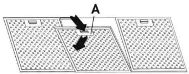
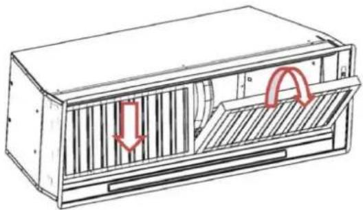
To remove the metal grease filter, see the installation manual, which will detail the procedure for your model, act on handle "A" or "B" until it detaches from the front guide; then tip the filter slightly downwards and detach it from the rear guide. Fitting is the reverse operation.
natural_image
Diagram showing a device interacting with a grid-patterned surface, labeled 'A' (no text or symbols present)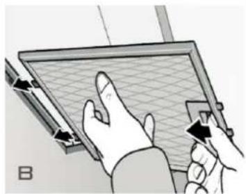
natural_image
Illustration of hands using a tool to interact with a grid-patterned screen (no text or symbols visible)The metal filters in the hoods are made of aluminium or stainless steel section, depending on the version and model, and the filter mesh is made of light alloy aluminium. It is important to remember that these filters must be changed for new ones when they are deteriorated, as they are an effective barrier to flames in case of sporadic fire (evidently they must be ALWAYS perfectly clean and free from grease.
It is recommended to wash them at least once every 15 days, depending on usage. As part of the maintenance of the filters, both aluminium and stainless, under normal average use, it advisable to replace them at least once a year.
Work or dirty filters are a source of suction problems, as the accumulation of grease will impede free flow of air, result in unnecessary noise and dripping, as well as the accumulation of grease inside the hood and its components.
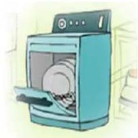
Filters can be hand washed with a standard detergent solution or in a dishwasher. It is recommended that hand washing be done without using SCOURING PADS, as this could damage the mesh, the best procedure is to wash by immersion and then rinse.
VERY IMPORTANT:
When washing in a DISHWASHER, take into account the instructions of the manufacturer regarding the washing of "ALUMINIUM UTENSILS". ALWAYS wash in a SHORT PROGRAMME WITHOUT DRYING OR SHINING and never hotter than 50°C. We recommend washing the filter alone, without any other utensils, so as to avoid bad smells caused by the filter remains affecting other kitchen utensils. When clean, leave to dry in the air.
If drying and polishing programmes or high cleaning temperatures are used by mistake, the filters could be blackened or stained and the mesh could be damaged or even disintegrate.
natural_image
Illustration of a blue washing machine with a door open, showing internal components (no text or symbols)8.2. CLEANING AND MAINTENANCE OF THE FILTERS
STAINLESS LABYRINTH FILTERS
This type of filter is removed in different manners according to the model or version, consult the installation manual that came with the hood.
It can be cleaned by hand or in a dishwasher in the same manner as the mesh filters, see detailed procedure and warnings on page 89 of the manual.
According to usage, the filter must be cleaned regularly, at least once every 2 months and depending on the version, if it has an oil collection tray, check it regularly and empty and clean before it overflows (optional depending on versions).
natural_image
Technical line drawing of a mechanical ventilation unit with airflow arrows (no text or symbols)TRAY TO COLLECT OIL (Optional, depending on model and version)
The hood must be disconnected from the mains before carrying out maintenance or cleaning,
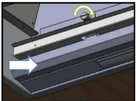
There are different systems or ways to remove the tray or tank according to model and version, as detailed in the attached installation manual. First remove the filters, with one hand hold the tank to avoid accidents or spills and with the other remove the securing screws or if it is secured by magnets, pull to remove.
Check the container for collecting grease an oil regularly, cleaning frequency will depend on usage, at least once every 2 months.
It can be cleaned by hand or in a dishwasher in the same manner as the mesh filters, see detailed procedure and warnings on page 89 of the manual.
natural_image
Interior view of a mechanical or architectural component with layered structure and a directional arrow (no text or symbols)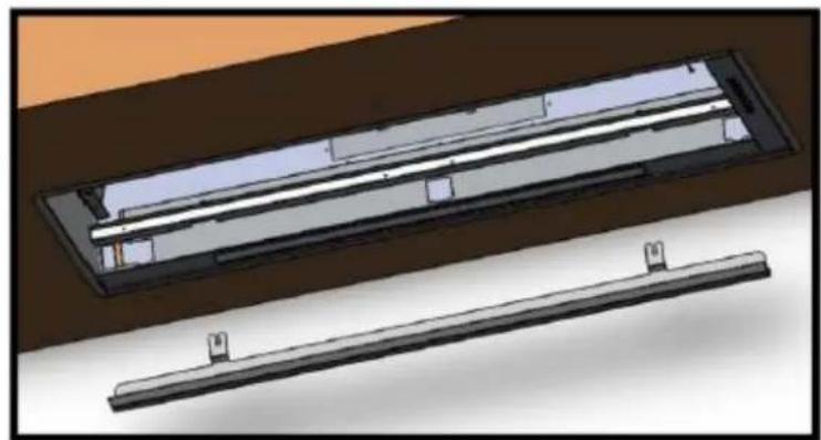
natural_image
3D rendering of two rectangular electronic components with internal parallel lines, shown from different angles (no text or symbols visible)8.2. CLEANING AND MAINTENANCE OF THE FILTERS
ACTIVE CARBON FILTERS (FCA) (Optional according to version, for hoods in Filter mode)
Recirculation or recycling of air extracted by a fume extractor hood is done through special active carbon filters. Its function is to purify the contaminated air:
This mode should only be used if it is not possible to install a fume conduit leading outside the kitchen or if an outlet causes noise or smell disturbance. The mode can also be used for ecological purposes, to avoid emitting pollutant gases into the atmosphere.
The incorporation of carbon filters will mean losing airflow in the hood and increasing noise levels, as the air is filtered through metal filters and the carbon filters. The fumes and smells are captured and recycled mostly directly, but there may be some fumes and above all some smell particles that the hood needs more time in operation to recycle, therefore it is always recommended to turn on the hood a few minutes before cooking and when you finish cooking, always leave it on until all the air in the kitchen has been recycled.
Removal and replacement of the activated carbon filter must always be done with the hood disconnected from the power supply completely off, since according to model and version must be manipulated inside the body of the hood. See manual assembly and installation in the bag attached documentation hood.
It is recommended to change the carbon filters every 120 hours of use or 4 months (Average daily use 1h) It is important to keep the metal filters clean and in perfect state, this will avoid shortening the life of the carbon filters, because they would end up getting soaked with grease particles that would block the surface fibres of the filter.
Active carbon filters (FCA) are not washable, nor can they be regenerated, once they have reached the end of their service life they must be replaced by new units.
EXAMPLES OF FITTING AND REPLACING ACCORDING TO VERSION:
- ROUND FCA FILTERS. Fitted threaded into the sides of the motor, using one quarter of a turn clockwise. It is recommended to replace them every 2 months.
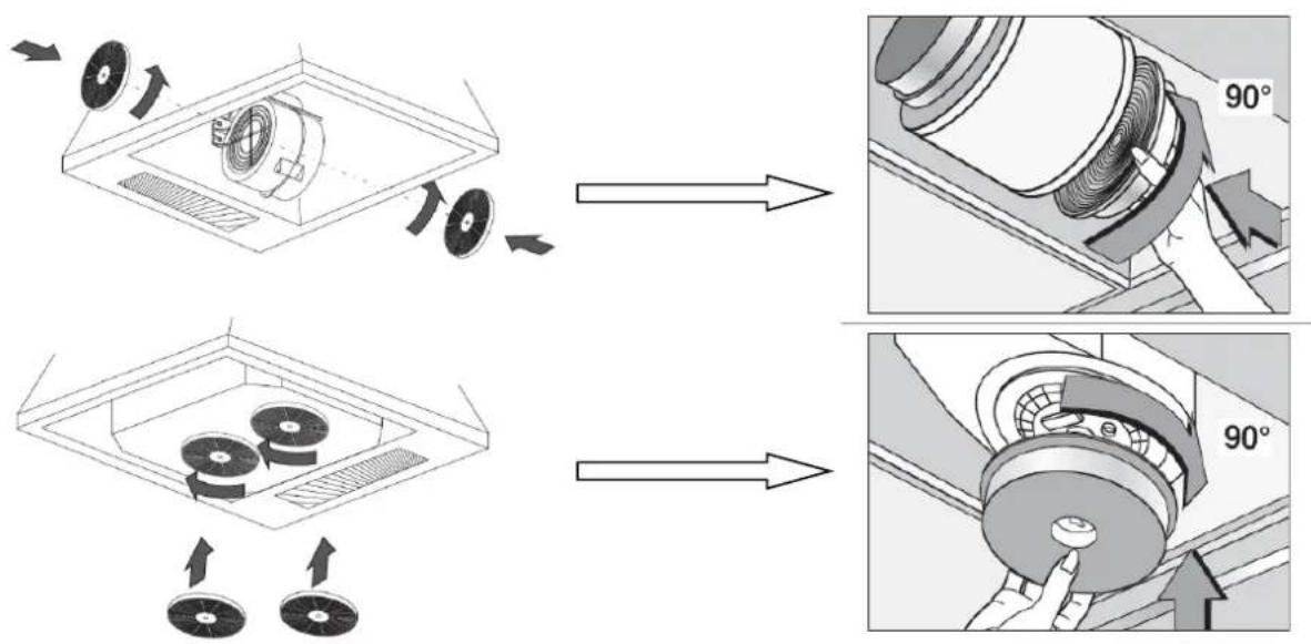
8.2. CLEANING AND MAINTENANCE OF THE FILTERS
ACTIVE CARBON FILTERS (FCA) (Optional according to version, for hoods in Filter mode)
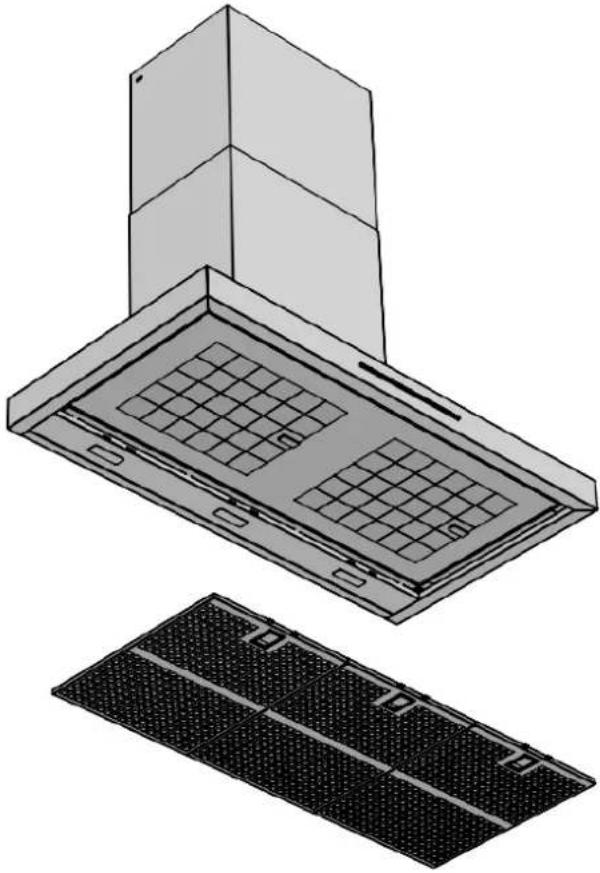
- FILTRE FCA FILTER. Fitted in the space in the FCA tray, do not remove the FCA tray. It is recommended to change them every 120 hours of use or 4 months (Average daily use 1h), they cannot be washed or reused.
natural_image
Technical illustration of a kitchen ventilation system with a top-mounted fan and a side-mounted rack (no text or symbols)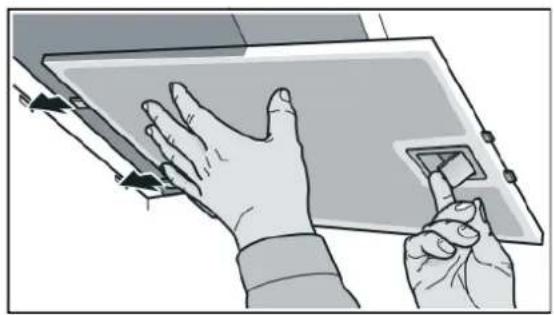
natural_image
Illustration of hands interacting with a tablet device (no text or symbols visible)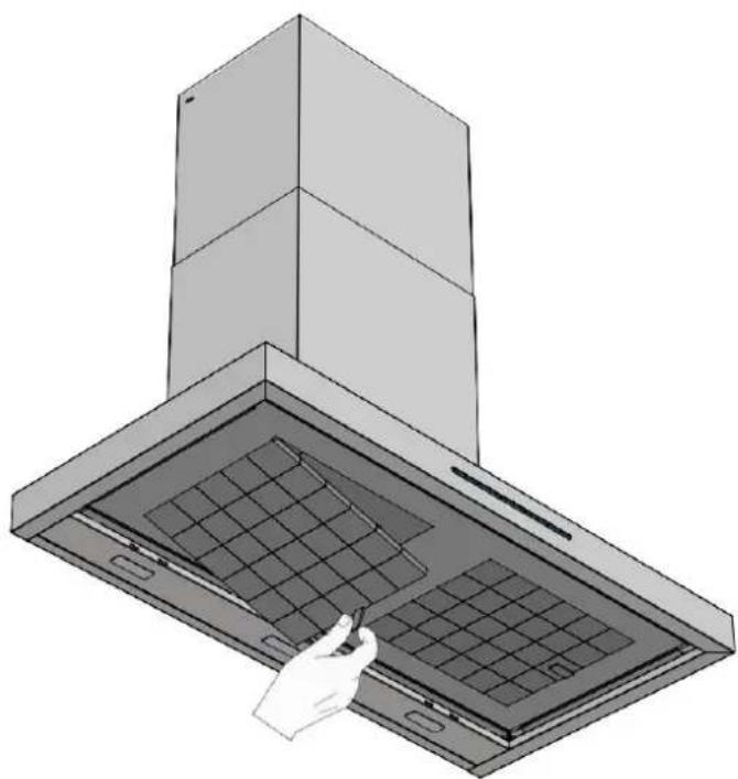
natural_image
Illustration of a kitchen chimney with a hand inserting a tool into the cover (no text or symbols)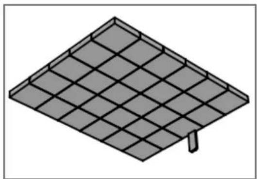
natural_image
Isometric illustration of a solar panel array with a single pin (no text or symbols)8.2. CLEANING AND MAINTENANCE OF THE FILTERS
HIGH EFFICIENCY REACTIVABLE CERAMIC ACTIVE CARBON FILTERS (FCCR AE) (Optional depending on version, for hoods in Filtering mode)
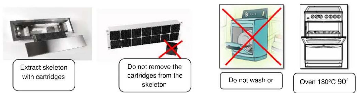
MAINTENANCE PROCESS AND REACTIVATION:
REACTIVATION every 90 hours of use or 3 months (Average daily use 1h)

Warning, use gloves to handle the filter, it has components in powder form that should not be ingested or come into contact with food, they could be toxic.

Warning, in the regeneration process in the oven, be careful with the components, which will be very hot, danger of burns, let it cool down before reinstalling.
1 – Remove the frame containing the packet of ceramic cartridges of the diffusor, IMPORTANT: do not remove the ceramic cartridges from the steel frame, as it keeps the structure together. It can be put into the oven with this frame.
2 - Regenerate in the oven at 180^ for 90 minutes.
3 – Wait for it to cool down and dry and then it will be regenerated and ready for use again.
IMPORTANT: Do not wash in a dishwasher, with soap etc., it must not come into contact with any liquid, as this would seriously damage the filter and could render it unusable.
The filter has a very long life, as it can be continually regenerated until the product loses it shape by wear or no longer regenerates.
To regenerate the ceramic filter, it is necessary to dispel smells / molecules of active carbon back to the atmosphere to recover its capacity of absorption. This process is called desorption.
Depending on the type of use and contaminants, there may be a reduction in the adsorption performance after each regeneration cycle, like a memory effect, this normally happens after 8-10 cycles. The estimated duration of the filters with performance over 50% is about 2-3 years, according to usage. It is advised to replace them for new ones every 10 cycles of reactivated, 900 hours of use or 2.5 years (average daily use 1h).
Due to the release of smells / molecules, it is recommended to carry out the regeneration in a well-ventilated room. The inlet and outlet of the filter must be unobstructed, to allow the elimination of the purged molecules. Do not let any cleaning product, solvents, detergents, oxidants, liquids, other filters, etc. come into contact with the ceramic filters.
Do not regenerate a filter if is it loaded with poisonous, dangerous, harmful for the environment or explosive contaminants.
8.2. CLEANING AND MAINTENANCE OF THE FILTERS
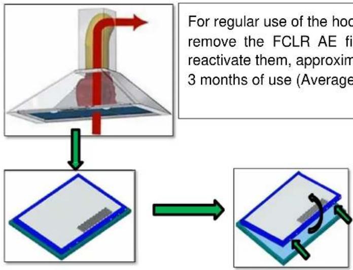
WASHABLE AND REACTIVATABLE ACTIVE HIGH EFFICIENCY CARBON FILTERS (FCLR AE) (Optional depending on version, for hoods in filter mode)
flowchart
graph TD
    A["Heating System"] --> B{Reactivation}
    B -->|For regular use of the hood remove the FCLR AE fil reactivate them, approxim 3 months of use (Average)| C["Reactivation Plate"]
    C --> D["Reactivation Plate with green arrows indicating rotation"]
For regular use of the hood, it is recommended remove the FCLR AE filters, wash them and reactivate them, approximately every 90 hours or 3 months of use (Average daily use 1h)
* According to version, "backpack type": Detach the FCLR carbon filter from the grease filter by pressing on the two tabs on the frame of the carbon filter and dethatch it at the same time as the grease filter.
(* Other models, its extraction is like a FCA standard, see manual flat FCA.)
CLEANING AND REACTIVATING THE FCLR FILTER:
Wash the FCLR AE carbon filter in a dishwasher at the maximum temperature by using common detergent; minimum temperature 65^ C and maximum temperature 70^ C. We recommend washing the filter alone, without any other utensils, so as to avoid bad smells caused by the filter remains affecting other kitchen utensils, when clean, leave to dry in the dishwasher or in the air.
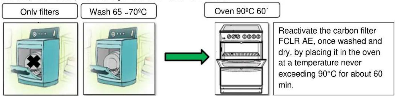
flowchart
graph LR
    A["Only filters"] --> B["Wash 65 ~70°C"]
    B --> C["Oven 90°C 60'"]
    C --> D["Reactivate the carbon filter FCLR AE, once washed and dry, by placing it in the oven at a temperature never exceeding 90°C for about 60 min."]
In normal use of the hood, after successive regeneration cycles, the FCLR AE carbon filter tends to have less capacity to absorb smells. It is recommended to change the filter every 10 cycles of reactivated, 900 hours of use or 2.5 years (average daily use 1h).
The life time reported is completely indicative, since the behaviour of the filter is influenced by many factors such as:
• The types of contaminants to which the filter is exposed and its concentration;
• The period of exposure;
• The speed and range of operation of the hood.
These can alter the behaviour of the filter even after regeneration significantly, see graph.
8.2. CLEANING AND MAINTENANCE OF THE FILTERS
WASHABLE AND REACTIVATABLE ACTIVE HIGH EFFICIENCY CARBON FILTERS (FCLR AE) (Optional depending on version, for hoods in filter mode)
In normal use of the hood at the average operating speed, after successive regeneration cycles, the FCLR AE carbon filter tends to have less capacity to absorb smells. It is recommended to change the filter every 10 cycles of reactivated, 900 hours of use or 2.5 years (average daily use 1h).
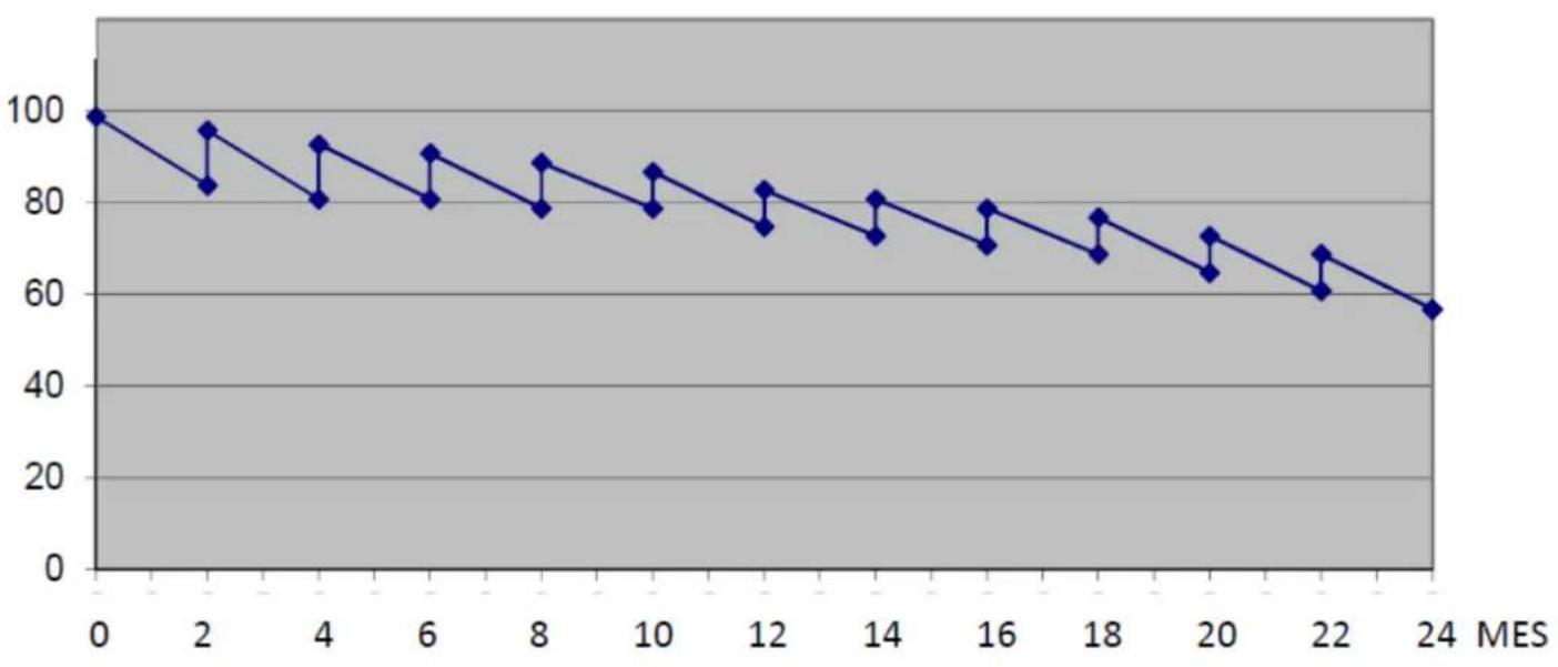
line
| MES | Value | | --- | ----- | | 0 | 100 | | 2 | 83 | | 4 | 92 | | 6 | 80 | | 8 | 88 | | 10 | 78 | | 12 | 85 | | 14 | 73 | | 16 | 79 | | 18 | 68 | | 20 | 72 | | 22 | 60 | | 24 | 56 |DISPOSAL OR RECYCLING OF FCA, FCLR AE AND FCCR AE FILTERS:
Regarding disposal, legislation requires all the carbon used to the analysed first and then disposed of according to the results of the analysis. In the case of domestic use, the compounds absorbed are not harmful for the environment and can therefore be disposed of as non-recyclable waste, in compliance with national and local regulations.
You can dispose of an exhausted filter in a centre or Clean Point for collection or local recycling point.
It is not recommended to regenerate any filter loaded with contaminants that are poisonous, dangerous, explosive or harmful for the environment.
8.3. MAINTENANCE OF THE LIGHTS
Removal and replacement of the lamps is made according to model or version of different forms, consult the manual assembly and installation int the bag attached documentation of the hood.
Changing the lamps must always be done with the hood disconnected from the mains, completely switched off, as internal electrical parts must be handled.
The lights are a component subject to wear and sensitive to improper handling, therefore they are not covered by the guarantee.
ATTENTION!

LED type lights involve a complex manipulation in addition to an air connection involving an internal connector risk of electric shock, therefore this type of handling must be done by the Pando official technical service or a qualified and authorized professional. The manufacturer will not be liable for any damage caused by mishandling of the LED lights by unauthorised personnel.

The original product LED lamps can purchase through the official technical assistance service Pando, user other than or equivalent to the original can cause damage or malfunction of the product that would not be covered by the manufacturer's warranty. The reference and characteristics of the lamps are described in the manual assembly and installation in the bag attached documentation of the hood.
EXAMPLES OF FITTING AND REPLACING ACCORDING TO VERSION:
- SQUARE LED 2.1W, 12vDC, 700Ma.
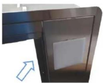
natural_image
Close-up of a metallic door or panel with a white square vent, showing a blue arrow pointing to the side (no text or symbols visible)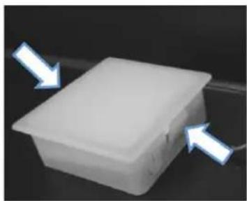
natural_image
White plastic container with two blue arrows pointing to its side (no text or symbols visible)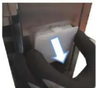
natural_image
Close-up of a mechanical component with a blue arrow pointing downward (no visible text or symbols)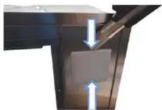
natural_image
Close-up of a mechanical component with two blue arrows indicating direction (no text or symbols)- LED MODULE OR STRIP (Different characteristics, consult the installation manual).
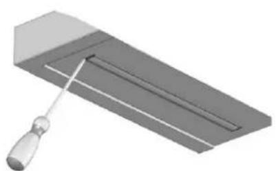
natural_image
3D illustration of a tool interacting with a rectangular object (no text or symbols visible)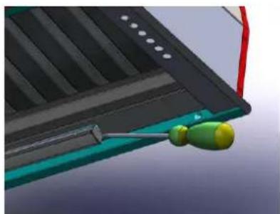
natural_image
Close-up of a mechanical component with a green and yellow tool, no visible text or symbols8.3. MAINTENANCE OF THE LIGHTS
- LED 1.2W, 12vDC, 350mA.
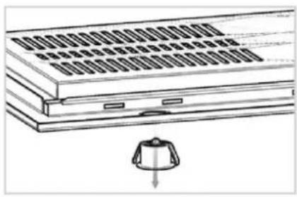
natural_image
Diagram of a multi-tiered electronic device with a small component below (no text or symbols visible)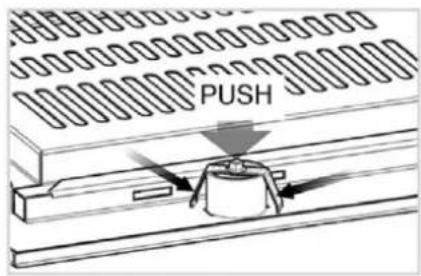
- LED 4W, 12v AC/DC, GU5.3.
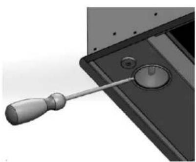
natural_image
Close-up of a screwdriver inserted into a mechanical component (no visible text or symbols)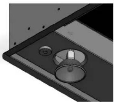
natural_image
Close-up of a mechanical component with circular features and a central knob (no visible text or symbols)- LED 1.3W, 12vDC 110mA
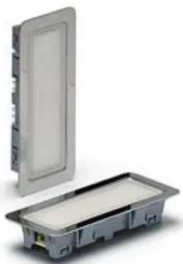
natural_image
Exterior view of a rectangular electronic device with a lid and internal casing (no text or symbols visible)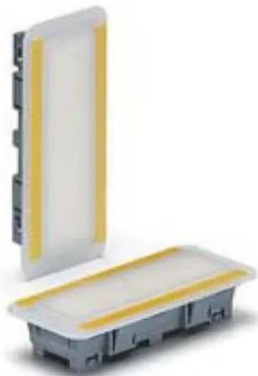
natural_image
Two electronic components with yellow and white bands, one partially enclosed by a transparent cover (no text or symbols visible)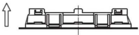
natural_image
Pure technical line drawing of a mechanical assembly without any text, numbers, or symbols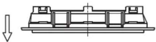
natural_image
Technical line drawing of a mechanical assembly with a downward arrow indicating force or direction (no text or symbols)9. TROUBLSHOOTING
| PROBLEM | SOLUTION |
| The hood does not work, neither the motor nor the lights.(Hood with control panel) | - Make sure the hood is connected to the mains, check that it plugged in and that the electricity is working, check if the circuit breaker has tripped.- Only in some models (especially those with a remote control), the hood has an emergency switch, make sure that it is ON.- Reset as follows:· Disconnect the hood from the mains with the electric panel circuit breaker and wait for 2 minutes before reconnecting.- If the problem is still not solved, contact Pando official technical service. |
| The hood does not work, either the motor nor the lights.(Hood without a control panel, controlled with a remote control) | - Make sure the hood is connected to the mains, check that it plugged in and that the electricity is working, check if the circuit breaker has tripped.- The hood has an emergency switch, make sure that it is ON.- Reset as follows:· Disconnect the hood from the mains with the electric panel circuit breaker and wait for 2 minutes before reconnecting.- Check that the remote-control battery is Ok, if not change the battery.- Synchronise the control with the hood, following the remote-control manual.- If the problem is still not solved, contact Pando official technical service. |
| The lights do not work. | - Check that the light is well connected and in good state.- If not replace the light. (In the case of an LED light, replacement must be done by the Pando official technical service or a qualified professional)- If the problem is still not solved, contact Pando official technical service. |
| The hood turns on by itself. | - In the case of remote controlled hoods or hoods prepared for remote control this can happen exceptionally. As the hood has a receiver which responds to a recorded code, it could happen that there is a hood nearby that is controlled with a remote control using the same code and this could affect your hood. To solve this problem, change the code of the receiver module, using the process for changing the control code and synching with your hood. Follow the instructions of your remote control in the section changing code and synching.- If the problem is still not solved, contact Pando official technical service. |
- TROUBLSHOOTING
| PROBLEM | SOLUTION |
| The hood turns off by itself. | - Make sure that the Last Time function was not active, this function will turn off the hood completely after a few minutes.- In the case of remote controlled hoods or hoods prepared for remote control this can happen exceptionally. As the hood has a receiver which responds to a recorded code, it could happen that there is a hood nearby that is controlled with a remote control using the same code and this could affect your hood. To solve this problem, change the code of the receiver module, using the process for changing the control code and synching with your hood. Follow the instructions of your remote control in the section changing code and synching.- If the problem is still not solved, contact Pando official technical service |
| The hood makes a lot of noise or vibrates a lot. | - Check the conduit installation, as some circumstances can increase the noise level and vibrations, such as:An exhaust conduit that has been badly sealed and badly secured.A conduit with less diameter than recommended.Bends or narrowing close to the motor outlet.Objects obstructing the natural air outlet of the conduit.Badly installed hood, not all the supports and fasteners supplied have been used.Check the material of the wall or ceiling the hood is attached to depending on the type of material, it may not be ideal and could be the cause or origin of amplified noise and vibrations. In these cases, it is recommended to dampen or insulate between the hood and the wall or ceiling, using rubber washers or silent-blocks.- If the problem is still not solved, contact Pando official technical service |
| The engine does not work. | - Reset as follows:1.Disconnect the hood from the mains with the electric panel circu breaker and wait for 2 minutes before reconnecting.- In case of a motor outside the hood, check the connections between the motor and the hood. (This should be done by a Pando officia technical service or a qualified professional)- If the problem is still not solved, contact Pando official technical service |
| Hood does not extract well. | - Check that the installation and usage conditions are Ok. Se section 2 in the manual. |
| The hood creates a lot of condensation. | - See attached bulletin for possible causes and recommendations. Page 100. |
| The remote control is not working well, sometimes it does not connect, it seems that it lacks power or range. | - Check the battery of the remote control, replace with a new one.- Check that there are no external elements that could interfere with the remote control signal, such as wireless devices like electric blinds digital weather stations, alarms with frequency inhibitors, wireless sound or audio systems, etc.- If the problem cannot be solved, contact Pando's official technical service. |
9. TROUBLSHOOTING
BULLETIN WITH RECOMMENDATIONS IN CASE OF EXCESSIVE CONDENSATION:
Condensation is caused by temperature differences between surfaces, causing thermal shock which leads to the forming of droplets that end up dripping onto the cooking area.
This is especially present when using induction cookers, as they only heat the cooking utensils and not the surrounding air, therefore the lower area of the hood is cold and when it comes into contact with emissions of steam with water and grease particles, these cool rapidly on the hood surface and generate droplets that end up dripping down. This effect is not present or only present to a lesser degree with Gas or Ceramic cookers, as these do heat up the surrounding air and pre-heat the lower part of the hood, thus avoiding a thermal shock.
If the evacuation conduit is not adequate, the problem will be worse as the lack of airflow due to irregularities in the conduit and the decreased speed of the air will also be the cause of internal condensation inside and outside the hood. For example, if the conduit is narrower than the manufacturer's recommendations, the airflow will be significantly reduced and the vapour will not be totally evacuated, the surplus remaining inside and outside the hood, cooling and accumulating on the hood surfaces, causing dripping.
When using induction cooktops, if you do not choose the right speed according to the cooking done, this condensation problem could arise or worsen.
Usage advice to avoid or minimise condensation: (This advice is useful if the installation and conduits are correct, and the motor power is adequate).
A) The hood should be connected 5 minutes before starting to cook and when you have finished, set the timer (LAST TIME) to evacuate the fumes in the conduit. This will totally evacuate the fumes.
B) Do not use the cooktop at maximum power from the beginning, i.e., start on low or medium power so as to give the steel or glass on the lower part of the hood time to warm up. If the type of cooking creates a lot of steam, use the hood at maximum power.
C) Keep the filters clean, they should be cleaned at least every 10 days and replaced if damaged, following the advice and frequency recommended by the manufacturer.
D) Having a continuous admission of air in the space, ensuring adequate ventilation that will help to absorb water vapour, will regulate humidity and improve the fluid extraction of the hood (ventilation grille, window partly open...).
E) When the cooking generates a lot of steam, it is recommended to use a lid on the cooking pot, partly uncovered to avoid overflow. In this manner, you can avoid a large part of the condensation and save energy and time.
INOXPAN S.L. will not be held liable for the correct operation of their products if they are not connected to an installation with an adequate conduit diameter as specified in the ∅ table with motor version.
10. PANDO GUARANTEE CERTIFICATE
INOXPAN S.L.
INOXPAN S.L., thank you for choosing our brand and for trusting a Pando product, standard of Quality, Design & Innovation, a brand honoring his origins and commitments.
TERMS OF THIS WARRANTY:
This product comes with a warranty of 3 year as from the date of purchase covering all product defect affecting its performance. To validate the same is mandatory to apply the purchasing invoice or buying ticket before the official Customer Service engineer.
During the above-mentioned period, the Company pledge to repair or replace at no cost any defective part whose cause is due to vice or manufacturing product flaw to make it work fine again, as well as the necessary labour cost and expenses involved in said repairing or replacement.
PANDO WARRANTY EXEMPTIONS:
It shall not be covered by the warranty or may be cause of cancelation of such, any of the following case scenarios, thus being the user the one taking charge of any material cost, labour and customer service travel expenses:
- Installation or performing reviews, extractor hood or ducting cleaning or maintenance.
- Failures or defects caused by not respecting or following the safety instructions, product use and maintenance manual recommendations.
- Whenever the product is orientated to commercial or non-residential use, to which it is not made for.
- Product malfunction caused by not following the instructions, recommendations and/or norms shown in the appliance manuals.
- Issues arising from any unappropriated product or smoke ducting installation
- Issues and faults produced by carriage or moves, and/or product handling by non-authorised personnel to this company or the brand Pando.
- Bumps, dents, scratches, or broken glasses
- Other alien bodies present in the interior or exterior of the product
- The product or any peripheral associated device, like in-line motors- might not be accessible, either due to elements impeding easy and safe access. All necessary means to access by the Pando authorised engineer shall be on account and responsibility of the user.
- Wiring inadequate handling and internal motor connections, remote or roof, and extractor hood.
- Wear and tear aesthetical parts, like lighting screens, filters and lamps.
- Rust, stains, tone changes produced by the use of inadequate non recommended corrosive cleaning products without the right protection, as those containing chemical corrosive agents, and /or exposure to the sea breeze (saltpetre).
- Issues or malfunction produced by variations of main supply, or natural and random causes from weather or geological origin, as storms, lightning, earthquakes, floods, etc
- Products whose origin is resale, used appliance, or displays with more than two years since their date of manufacturing.
INOXPAN, S.L., remains expressly excluded from any liability over any eventual damage any direct or indirect to persons or materials produced by inadequate product handling and use.
Official Pando Customer Service Contact Details
| SPAIN, PORTUGAL Y ANDORRA: | OTHER COUNTRIES / AUTRES PAYS | ||
| https://www.pando.es/asistencia-tecnica/ |  | ENhttps://www.pando.es/en/after-sales-services/FRhttps://www.pando.es/fr/service-apres-vente/ |  |
NOTES:
NOTES:
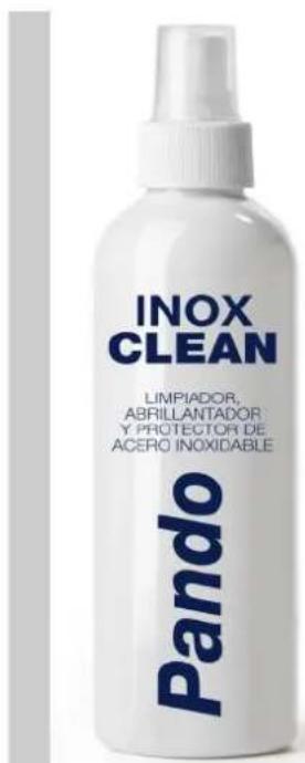
PRODUIT UNIQUE
FR
NETTOYANT,
Lustrant ET
PROTECTEUR D'ACIER INOXYDABLE
INOX PANDO, Referencia 1059.
PROPRIÉTÉS :
Degreaser especially recommended for polishing stainless steel surfaces, with its complex formula based on paraffin it leaves an invisible film that acts as a protector and makes it shine.
APPLICATIONS:
Cleans, polishes and evens out stainless steel surfaces of extractor hoods and stainless steel kitchen furniture.
INOXPAN S.L.
Pol. Ind. El Cros
SERVICIO POST VENTA España, Portugal y Andorra
Quality ManagementSystem
UNE-EN ISO 9001:2015
ES19/86566

CE
natural_image
Modern minimalist interior design featuring a multi-level staircase with open shelves and wall-mounted panels, alongside close-up views of lighting fixtures (no text or symbols visible)Pando integralcooking
CAMPANAS DECORATIVAS

natural_image
Simple line drawing of a trash bin with no text or symbols2. RECOMANDĂRILE CE URMEAZĂ A FI LUATE ÎN CONSIDERARE ÎNAINTE DE INSTALARE.
natural_image
Simple line drawing of a faucet with a red X mark crossed out, no text or symbols present.INCORECT
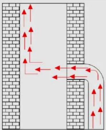
natural_image
Diagram showing airflow or movement between two brick walls with red arrows indicating direction (no text or symbols)CORECT
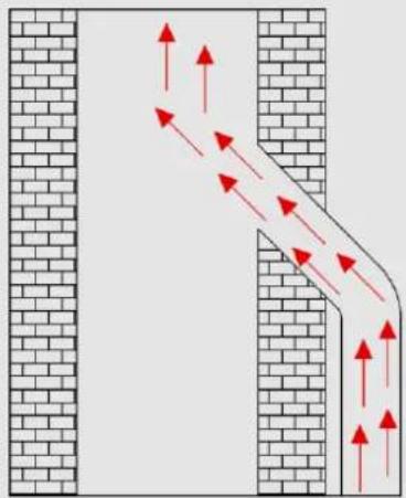
natural_image
Diagram of a pipe or channel with red arrows indicating flow direction, flanked by brick walls (no text or symbols)OPTIM
natural_image
Close-up of a textured, elongated object with no visible text or symbols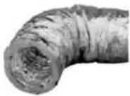
• CERINȚE FATĂ DE DIMENSIUNI ȘI SPATII:
2. RECOMANDĂRILE CE URMEAZĂ A FI LUATE ÎN CONSIDERARE ÎNAINTE DE INSTALARE.
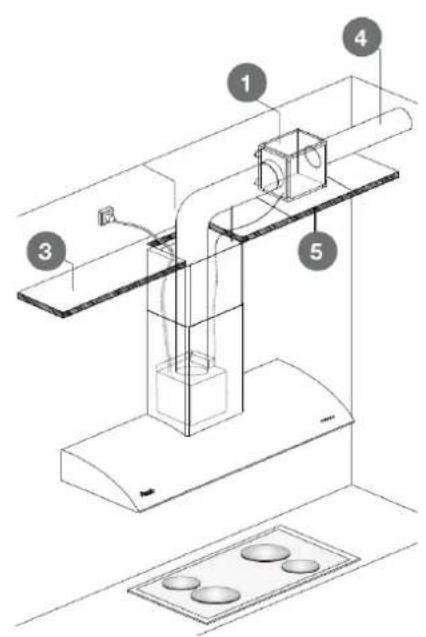

Motorul

| 2700......6000°k 2700......4000°k | |
| tunable |
natural_image
Two simple icons: a power button and a pie chart, both with radiating lines (no text or symbols)natural_image
Technical line drawing of a rectangular frame with two internal compartments and circular holes, no text or symbols present.natural_image
Metallic rectangular electronic component with a slot and mounting holes (no visible text or symbols)S.I.A. Safety - APAGADO DE SEGURIDAD AUTOMÁTICO (5h)
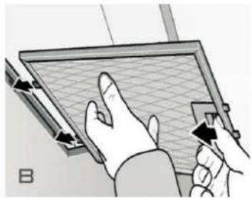
natural_image
Illustration of hands using a tool to interact with a grid-patterned screen (no text or symbols visible)natural_image
Illustration of a blue washing machine with a door open, showing internal components (no text or symbols)8.2. CURĂTAREA SI DESERVIREA TEHNICĂ A FILTRELOR:
FILTRELE DIN OTEL INOXIDABIL CU LABIRINT
natural_image
Technical line drawing of a mechanical ventilation unit with airflow arrows (no text or symbols)natural_image
3D architectural diagram showing a window with a knob and directional arrow, no text or symbols present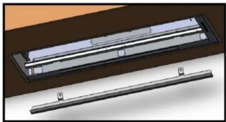
natural_image
3D CAD model of a rectangular electronic component with internal parallel strips, shown from two different angles (no text or symbols)8.2. CURĂTAREA SI DESERVIREA TEHNICĂ A FILTRELOR:
8.2. CURĂTAREA SI DESERVIREA TEHNICĂ A FILTRELOR:
natural_image
Technical illustration of a kitchen ventilation system with a top panel and a bottom panel (no text or symbols)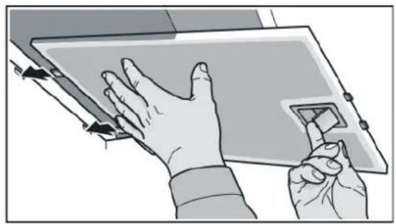
natural_image
Illustration of hands interacting with a tablet device (no text or symbols visible)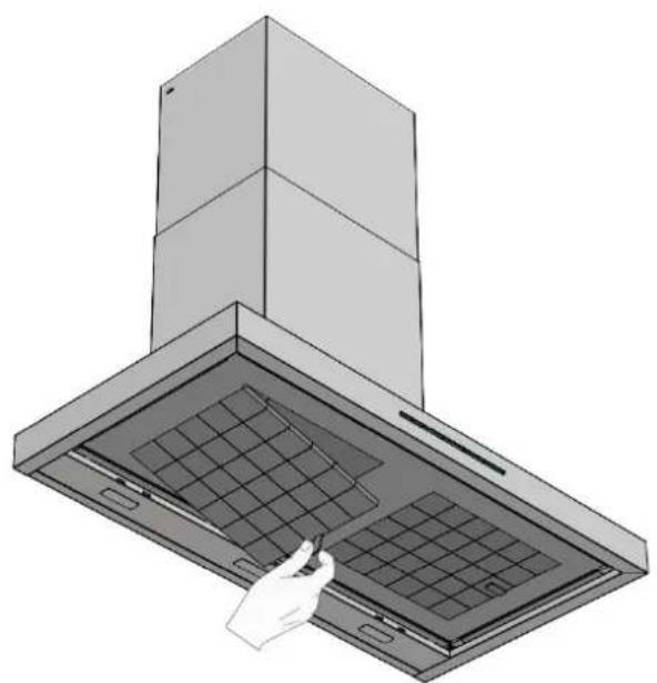
natural_image
Illustration of a kitchen chimney with a hand inserting a component into the cover (no text or symbols)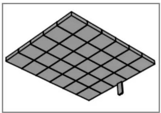
natural_image
Isometric illustration of a solar panel array with grid pattern (no text or symbols)8.2. CURĂTAREA SI DESERVIREA TEHNICĂ A FILTRELOR:
natural_image
3D CAD model of a mechanical component with a tool inserted, shown from two different angles (no text or symbols visible)8.3. DESERVIREA SISTEMULUI DE ILUMINARE:
natural_image
Diagram of a multi-tiered electronic device with a small component below (no text or symbols visible)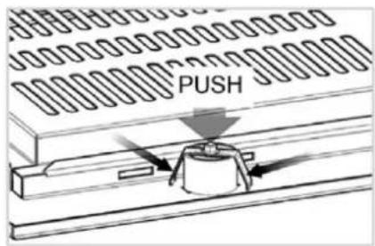
natural_image
Close-up of a screwdriver inserted into a mechanical component (no visible text or symbols)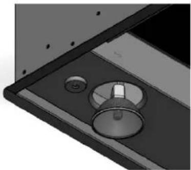
natural_image
Close-up of a mechanical component with circular features and a central knob (no visible text or symbols)natural_image
Exterior view of a rectangular electronic device with a transparent lid and internal components (no text or symbols visible)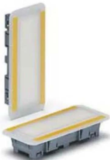
natural_image
Two electronic components with yellow and white bands, one partially enclosed by a white panel (no text or symbols visible)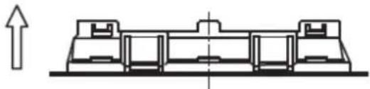
natural_image
Pure technical line drawing of a mechanical assembly without any text, numbers, or symbols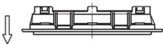
natural_image
Technical line drawing of a mechanical assembly with a downward arrow indicating force or direction (no text or symbols)- ÎNLĂTURAREA DEFECTELOR:
SERVICIO POST VENTA España, Portugal y Andorra
Quality ManagementSystem
UNE-ENISO 9001:2015
ES19/86566

CE
natural_image
Modern minimalist interior design featuring a multi-level staircase with open shelves and wall-mounted panels, alongside close-up views of the exterior (no text or symbols visible)Pando
integralcooking
ДЕКОРАТИВНЫЕ
ВЫТЯЖКИ
EAC

natural_image
Diagram of a mechanical or fluid system with directional arrows and a circular component, no text or symbols present.Рис. 1
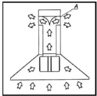
natural_image
Diagram of a mechanical or fluidic device with directional arrows and a labeled point A, no readable text or symbols present.Рис. 2
natural_image
Simple line drawing of a faucet with a red X mark crossed out, no text or symbols present.natural_image
Close-up of a textured, dark gray rectangular object with no visible text or symbols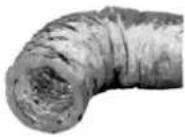
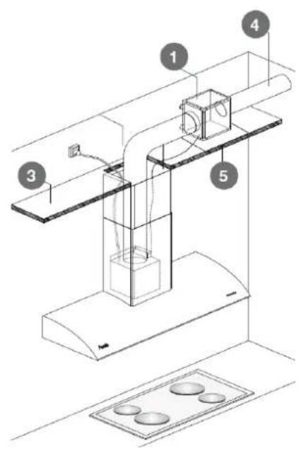

Мотор

natural_image
Two technical line drawings of a building interior with ventilation ducts and storage compartments (no text or symbols)natural_image
Two simple icons: a power button and a circular pie with a minus sign, both radiating from each other (no text or symbols)natural_image
Technical line drawing of a rectangular frame with internal compartments and mounting holes, no text or symbols presentnatural_image
Metallic electrical outlet bracket with internal slots and mounting holes (no text or symbols visible)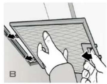
natural_image
Illustration of hands interacting with a grid-patterned panel or board (no text or symbols visible)natural_image
Illustration of a blue washing machine with a lid removed (no text or symbols visible)natural_image
Technical line drawing of a mechanical ventilation unit with airflow arrows (no text or symbols)natural_image
3D architectural diagram showing a window with a knob and directional arrow, no text or symbols present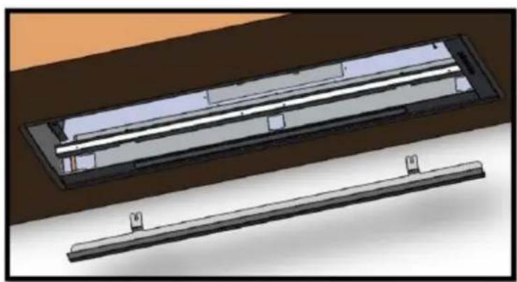
natural_image
3D CAD model of a rectangular electronic component with internal parallel strips, shown from two different angles (no text or symbols)natural_image
Interior view of a computer monitor case showing internal components (no visible text or labels)natural_image
Solar panel array with a red X symbol indicating prohibition (no text or labels)natural_image
Illustration of a washing machine with red prohibition symbols (no text or labels)natural_image
Line drawing of a double boiler with front panel and side bays (no text or symbols)natural_image
Diagram of a conical funnel with red and green airflow arrows indicating fluid or material flow (no text or symbols)natural_image
3D rendering of a blue and green electronic component with a small gray internal feature (no text or symbols)
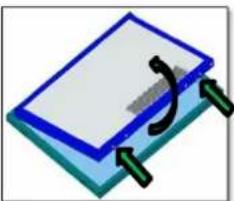
natural_image
Simple 3D illustration of a blue rectangular object with a curved arrow and green connectors, no text or symbols present.natural_image
Illustration of a washing machine with a black cross symbol inside, no text or symbols presentМойка при 65—70 °C
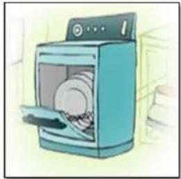
natural_image
Illustration of a blue washing machine with a door open, showing internal components (no text or symbols)natural_image
Line drawing of a double boiler with front panel and side bays (no text or symbols)natural_image
Close-up of a dark metal panel with a white square recess, showing a blue arrow pointing to the side (no text or symbols visible)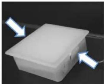
natural_image
White rectangular plastic container with two light blue arrows pointing to its side (no text or symbols visible)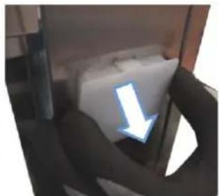
natural_image
Close-up of a person's arm holding a white object with a blue arrow pointing downward (no text or symbols visible)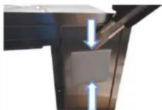
natural_image
Close-up of a mechanical component with two white arrows indicating direction (no text or symbols)natural_image
3D illustration of a tool interacting with a rectangular object (no text or symbols visible)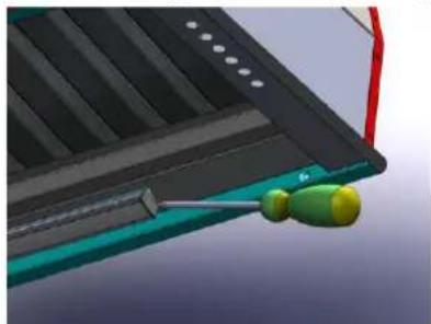
natural_image
Close-up of a mechanical component with a green and yellow tool inserted, no visible text or symbols8.3. ОБСЛУЖИВАНИЕ ОСВЕЩЕНИЯ:
natural_image
Diagram of a multi-tiered electronic device with a small bell icon below (no text or symbols)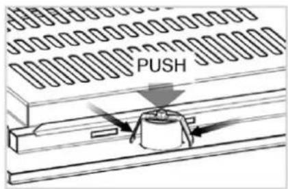
natural_image
Close-up of a screwdriver inserted into a mechanical component with a circular dial (no text or symbols visible)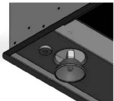
natural_image
Close-up of a mechanical component with circular features and a central knob (no visible text or symbols)natural_image
Exterior view of a rectangular electronic device with a lid and internal casing (no text or symbols visible)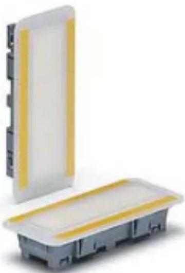
natural_image
Exterior view of a modular electronic device with a white panel and yellow stripe, no visible text or symbols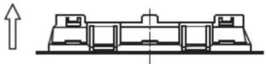
natural_image
Pure technical line drawing of a mechanical assembly without any text, numbers, or symbols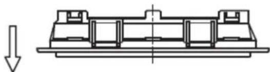
natural_image
Technical line drawing of a mechanical assembly with a downward arrow indicating force or direction (no text or symbols)
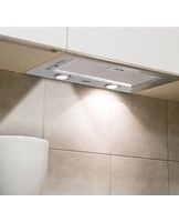

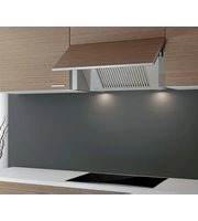
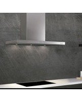
- Pando
- integralcooking
- HOTTES DÉCORATIVES DECORATIVE COOKER HOODS
- RECOMMANDATIONS À PRENDRE EN COMPTE AVANT L'INSTALLATION
- • DISTANCES ET TAILLE APPROPRIÉE :
- MOTEUR MURAL DE FAÇADE:
- CARACTÉRISTIQUE DU CONDUIT D'ÉVACUATION SELON LA VERSION DU MOTEUR.
- S.I.A. Safety ARRÊT DE SÉCURITÉ AUTOMATIQUE (5h)
- • ALARME SATURATION FILTRES:
- - FILTRES MÉTALLIQUES:
- Échecs de communication:
- NETTOYAGE ET ENTRETIEN DES FILTRES
- FILTROS LABYRINTHE INOX
- ÉLIMINATION OU RECYCLAGE DES FILTRES FCA, FCLR AE Y FCCR AE:
- ENTRETIEN DES LAMPES
- ENVIRONMENTAL PROTECTION AND WASTE TREATMENT
- CONTENTS
- SAFETY INSTRUCTIONS
- RECOMMENDATIONS TO BEAR IN MIND BEFORE INSTALLATION.
- VERY IMPORTANT!
- • CONDUIT FOR EVACUATING FUMES AND SMELLS:
- • THE RIGHT SIZE AND DISTANCES:
- CONDUIT ACCESSORIES (Optional).
- INSTALLING AN SEC System conduit (Included only in SEC versions)
- ELECTRICAL CONNECTION (Only to be done by qualified professionals)
- Key for power cables:
- INSTALLATION OF EXTERIOR, ROOF OR WALL MOTOR (According to versions)
- FALSE CEILING EXTERIOR MOTOR:
- CHARACTERISTICS OF THE EXTRACTION CONDUIT ACCORDING TO MOTOR TYPE
- NOTES:
- INSTRUCTIONS FOR USING THE CONTROLS.
- TIMER "Ecodesign"
- SPECIAL FUNCTIONS (Pando LED-AIR Clean)
- Pando LED (Function only for models with Pando LED logo on their internal label)
- ELECTRONIC PANEL
- FILTER SATURATION WARNING (30h).
- S.I.A. Safety - AUTOMATIC SAFETY DISCONNECTION (5h)
- 1.1. Pando LED. Setting Mode with electronic panel.
- 1.2. Pando AIR Clean with electronic panel.
- SATURATION FILTER ALARM:
- - FOR METALIC FILTERS (Lighting symbol lickers):
- - FOR REACTIVABLE CARBON FILTERS (FCA/ FCLR AE):
- 2.1. Pando LED. Setting mode with touch invisible control panel.
- Pando AIR Clean mode with touch invisible control panel.
- ELECTRONIC DISPLAY PANEL
- ELECTRONIC PANEL WITH INTENSIVE 3i
- MAINTENANCE FUNCTIONS:
- - CLEAN AIR:
- • FILTER SATURATION ALARM:
- - MESH FILTERS:
- - ACTIVE CARBON FILTERS (FCA):
- MECHANICAL BUTTON PANEL
- SLIDER PANEL
- Pando REMOTE CONTROL TOUCH RF
- Pando LED setting mode with remote control TOUCH RF.
- Pando AIR Clean with remote control TOUCH RF.
- SATURATION OF FILTERS IN PILOT-BEEP AERIAL MODULE
- Pando multicolour pilot light without button panel
- HOODS WITHOUT BUTTON PANEL – ACOUSTIC AND VISUAL CONFIRMATION MODUL:
- ON/OFF SAFETY BUTTON, OPTIONAL DEPENDING ON HOOD MODEL AND VERSION
- ACOUSTIC CONFIRMATION DEVICE (BEEP)
- WALL MOUNTED BUTTON CONTROL SWITCH (Option upon request.)
- Adjustment and Calibration remote control TOUCH RF.
- A - SYNCHRONIZATION REMOTE CONTROL (\* only if necessary, it is already synchronized):
- DO NOT TOUCH ANY COMMAND KEY UNTIL AFTER 5 SECONDS
- MAINTENANCE
- TROUBLESHOOTING:
- Emergency key:
- Communication failure:
- WARNING:
- CLEANING AND MAINTENANCE
- CLEANING AND MAINTENANCE OF THE HOOD
- ENAMELLED HOODS
- CORIAN HOODS
- The following is not covered by the guarantee:
- DEKTON HOODS
- Precautions:
- STAINLESS HOODS
- RECOMENDACIONES:
- Cleaning products containing BLEACH, ACID, CAUSTIC SODA, AMMONIA, CHLORIDES or DERIVED CORROSIVE AGENTS will HARM the stainless steel.
- VERY IMPORTANT:
- CLEANING AND MAINTENANCE OF THE FILTERS
- ALUMINIUM AND STAINLESS FILTERS
- STAINLESS LABYRINTH FILTERS
- TRAY TO COLLECT OIL (Optional, depending on model and version)
- ACTIVE CARBON FILTERS (FCA) (Optional according to version, for hoods in Filter mode)
- EXAMPLES OF FITTING AND REPLACING ACCORDING TO VERSION:
- MAINTENANCE PROCESS AND REACTIVATION:
- CLEANING AND REACTIVATING THE FCLR FILTER:
- WASHABLE AND REACTIVATABLE ACTIVE HIGH EFFICIENCY CARBON FILTERS (FCLR AE) (Optional depending on version, for hoods in filter mode)
- DISPOSAL OR RECYCLING OF FCA, FCLR AE AND FCCR AE FILTERS:
- MAINTENANCE OF THE LIGHTS
- ATTENTION!
- TROUBLSHOOTING
- BULLETIN WITH RECOMMENDATIONS IN CASE OF EXCESSIVE CONDENSATION:
- PANDO GUARANTEE CERTIFICATE
- INOXPAN S.L.
- TERMS OF THIS WARRANTY:
- PANDO WARRANTY EXEMPTIONS:
- PROPRIÉTÉS :
- APPLICATIONS:
- Pando integralcooking
- CAMPANAS DECORATIVAS
- RECOMANDĂRILE CE URMEAZĂ A FI LUATE ÎN CONSIDERARE ÎNAINTE DE INSTALARE.
- • CERINȚE FATĂ DE DIMENSIUNI ȘI SPATII:
- S.I.A. Safety - APAGADO DE SEGURIDAD AUTOMÁTICO (5h)
- CURĂTAREA SI DESERVIREA TEHNICĂ A FILTRELOR:
- FILTRELE DIN OTEL INOXIDABIL CU LABIRINT
- DESERVIREA SISTEMULUI DE ILUMINARE:
- ДЕКОРАТИВНЫЕ
- ВЫТЯЖКИ
- ОБСЛУЖИВАНИЕ ОСВЕЩЕНИЯ:
Brand : Pando
Model : EVO
Category : Range hood