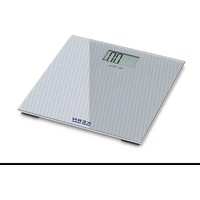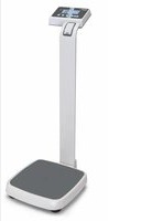
MPE 250K100HNM - Scale Kern - Free user manual and instructions
Find the device manual for free MPE 250K100HNM Kern in PDF.


User questions about MPE 250K100HNM Kern
0 question about this device. Answer the ones you know or ask your own.
Ask a new question about this device
Download the instructions for your Scale in PDF format for free! Find your manual MPE 250K100HNM - Kern and take your electronic device back in hand. On this page are published all the documents necessary for the use of your device. MPE 250K100HNM by Kern.
USER MANUAL MPE 250K100HNM Kern
text_image
KERN TARE →0← F PRINT BMI HOLD ON OFFD
Weitere Sprachversionen finden Sie online unter www.kern-sohn.com/manuals
CZ
Další jazykové verze najdete na webu pod adresou www.kern-sohn.com/manuals
DK
Yderligere sprogversioner finder de online på www.kern-sohn.com/manuals
E
Más versiones de idiomas se encuentran online bajowww.kern-sohn.com/manuals
EST
Rohkem keeli internetis aadressil www.kern-sohn.com/manuals
F
Vous trouverez d'autres versions de langue online sous www.kern-sohn.com/manuals
GB
Further language versions you will find online under www.kern-sohn.com/manuals
H
A használati utasítás egyéb nyelveken a www.kern-sohn.com/manuals címről tölthető le
①
Trovate altre versioni di lingue online inwww.kern-sohn.com/manuals
N
Ytterligere språkversjoner finner du online under www.kern-sohn.com/manuals
NL
Bijkomende taalversies vindt u online op www.kern-sohn.com/manuals
P
Encontram-se online mais versões de línguas em www.kern-sohn.com/manuals
PL
Inne wersje językowe znajdą Państwo na stroniewww.kern-sohn.com/manuals
RUS
Другие языковые версии Вы найдете по адресу в Интернете www.kern-sohn.com/manuals
S
Ytterligare språkversioner finns online under www.kern-sohn.com/manuals
SF
Muita kieliversioita löydät osoitteesta www.kern-sohn.com/manuals
SLO
Ostale jezikovne različice boste našli online na www.kern-sohn.com/manuals
TR
Diğer lisan versiyonlarını internetten www.kern-sohn.com/manuals adresinden temin edeblirsiniz

KERN KMF-TM
Version 1.0 06/2013
text_image
KERN 0.0 kg TARE →0← F PRINT BMI HOLD ON ① ② ③ ④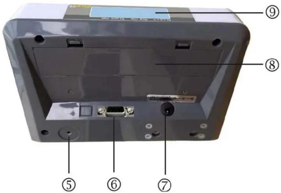
text_image
⑨ Max 200 kg Max 200 mm ⑧ ⑤ ⑥ ⑦text_image
KERN TARE →0← F PRINT BMI HOLD ON OFFTaste Funktion

Waage tarieren

text_image
Technical diagram of a device with labeled components including ports, connectors, and parts numbered 1, 2, and 3.text_image
KERN Max 20 kg Min 0.2 kg v=0.01 kg TARC →0← →0← HOLD ON OFFnatural_image
White medical or dental imaging device with adjustable arm and screen (no visible text or symbols)natural_image
White medical or dental implant device with a rectangular base and rounded top, no visible text or symbols.Abb. 3 MBC Waage.
text_image
KERN Max 250 kg Min 2 kg e=0.1 kg TARE →0← F BMI HOLD ON OFFnatural_image
White and gray electronic device with a black cable, no visible text or symbolsnatural_image
Two white digital balance scale devices with adjustable legs and a vertical stand, no visible text or symbols.natural_image
3D rendered image of a white and dark gray electronic device with a rectangular base (no text or symbols visible)Abb. 10 MPD Personenwaage.
text_image
KERN MC Max 250 kg Min 2 kg d = 0.1 kg TARE →0+ F BMI HOLD ON OFFnatural_image
White medical mobility chair with black seat and wheels, no visible text or symbolsAbb. 12 MCC Rollstuhlwaage
text_image
self destroy label seal plate (ABS) calibration switch self destroy labeltext_image
self destory label self destroy label seal plate (ABS) calibration switch3 Basic instructions....8
3.1 Proper use 8
3.2 Improper Use 8
3.3 Warranty 8
3.4 Monitoring of Test Resources 9
4 Basic Safety Precautions....9
4.1 Pay attention to the instructions in the Operation Manual 9
4.2 Personnel training....9
5 Transport and storage....9
5.1 Testing upon acceptance....9
5.2 Packaging / return transport....9
6 Unpacking, Setup and Commissioning 10
6.1 Place of installation / place of operation....10
6.2 Unpacking....10
6.3 Scope of delivery 10
6.4 Mains connection....11
6.5 Rechargeable battery operation....11
6.6 Initial Commissioning....11
7 Operation.... 12
7.1 Start-up....12
7.2 Switching Off 12
7.3 Zeroing 12
7.4 Weighing....12
7.5 Taring 12
7.5.1 Subsequent tare weight.... 13
7.6 Data-Hold function....13
7.7 See second decimal point (not verified value)....13
7.9 Calculation of the Body Mass Index....14
7.9.1 Classification of BMI values 15
7.10 Automatic switch-off function „AUTO OFF“ 15
7.11 Display background illumination....16
8 Data output RS 232....17
8.1 Pin allocation of balance output bushing:....17
8.2 Technical data ....17
8.3 Printer operation....18
9 Error messages.... 19
10 Servicing, maintenance, disposal 19
10.1 Clean....19
10.2 Servicing, maintenance....19
10.3 Disposal....19
11 Instant help.... 20
12 Installation display unit 21
12.1 Technical data 21
12.2 Weighing system design....21
12.3 How to connect the platform 22
12.4 Configure display unit 23
12.4.1 Navigation in the menu 23
12.4.2 Menu overview 24
12.4.3 Carry out configuration....27
13 Verification 30
14 Adjustment 32
15 Enclosure Type Approval Certificate when using as weighing system KERN MPD 34
1 Technical data
| KERN KMF-TM | |
| Display 6-digit | |
| Resolution verified 6.000 | |
| Resolution not verified 30.000 | |
| Divisions 1,2,5,...10n | |
| Verification class III | |
| Weighing Units kg | |
| Functions Data-Hold, BMI | |
| Display | LCD 25 mm digits with back lighting |
| DMS weighing cells | 80-100 Ω. Max. 4 item per 350 Ω; Sensitivity 2-3 mV/V |
| Range calibration | We recommend ≥ 50 % max. |
| Electric Supply | Input voltage 220 V – 240 V, 50 Hz |
| Power pack secondary voltage 12V, 500mA | |
| Dimensions (B x D x H) mm | 195 x 118 x 83 |
| Admissible ambient temperature | -10°C – 40°C |
| Net weight | 1 kg |
| Medical product in accordance with 93/42/EEC | Class I when using as weighing system KERN MPD |
2 Appliance overview
text_image
KERN 0.0 kg TARE →0← F PRINT BMI HOLD ON OFF ① ② ③ ④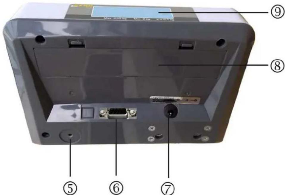
text_image
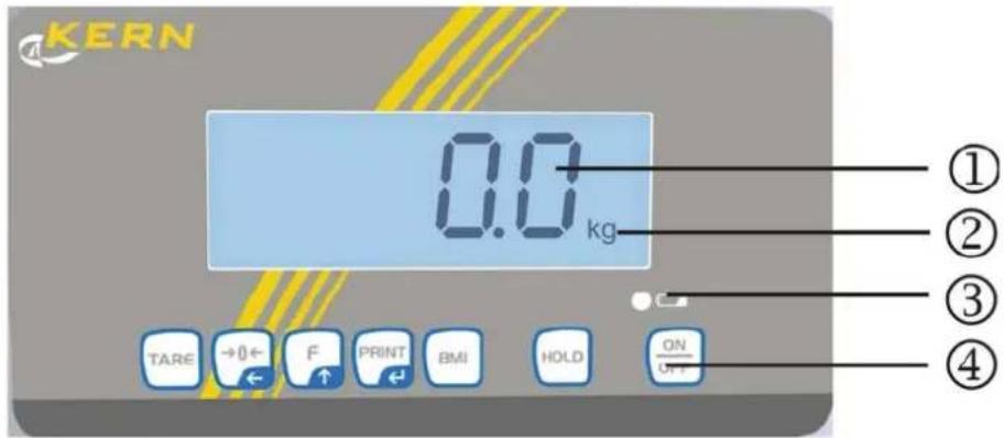
⑨ Max 200 kg Max 250 kg ⑧ ⑤ ⑥ ⑦- Weight display
- Weighing unit
- Battery charge status
- Keyboard
- Adjustment switch
- RS232
- Terminal power supply unit
- Battery compartment
- Secondary display at rear
2.1 Overview of display

text_image
W1 W2 DRINK PT BMI HOLD M1 M2 M3 M4 STABLE ZERO cm inch -8.88.88.8 lb kg TARE NET GROSS| Display | Description | Description |
| STABLE | Stability display | Scales are in a steady state |
| ZERO | Zeroing display Should the balance not display exactly zero | |
| despite empty weighing plate, press the button. Your balance will be set to zero after a short standby time. | ||
| NET | Net weight display | Illuminated when net weight is displayed |
| Illuminated after weighing scale was tared | ||
| GROSS | Gross weight display | Illuminated when gross weight is displayed |
| HOLD | HOLD function HOLD function active | |
| BMI | BMI function | Illuminated while BMI function is enabled |
| Rechargeable battery symbol | Lights when the voltage drops below the prescribed minimum. | |
| Lights when the rechargeable battery capacity is almost exhausted. | ||
| Lights when the rechargeable battery is fully charged. | ||
2.2 Keyboard overview
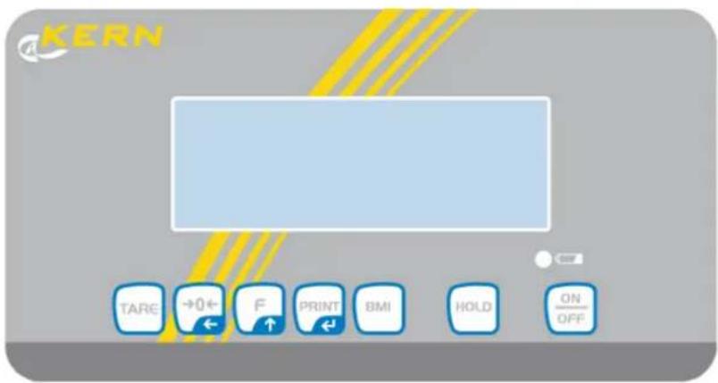
text_image
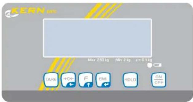
KERN TARE →0← F PRINT BMI HOLD ON OFFKey Function

Tare balance

Weighing scale will be reset to „0.0“
For numeric entry:
- Change decimal place

In menu:
- Call up menu
- Select menu items
For numeric entry:
- Increase numerical value

Data transfer via RS 232
In menu:
- Confirm selection
For numeric entry:
- Confirm numerical value

Calculation of the Body Mass Index

Data-Hold function

Turn on/off
3 Basic instructions
3.1 Proper use
The display unit acquired by you is used in combination with a load cell and serves to determine the weighing value of material to be weighed. It is intended to be used as a “non-automatic weighing system”, i.e. the material to be weighed is manually and carefully placed in the centre of the weighing plate. As soon as a stable weighing value is reached the weighing value can be read.
3.2 Improper Use
Do not use weighing system for dynamic weighing. In the event that small quantities are removed or added to the material to be weighed, incorrect weighing results can be displayed due to the “stability compensation” in the display unit. (Example: Slowly draining fluids from a container on the balance.)
Do not leave permanent load on the load cell. This may damage the measuring system.
Impacts and overloading exceeding the stated maximum load (max) of the load cell, minus a possibly existing tare load, must be strictly avoided. The load cell or the display unit may be damaged during this process.
Never operate display unit in explosive environment. The serial version is not explosion protected.
Changes to the display unit's design are not permitted. This may lead to incorrect weighing results, safety-related faults and destruction of the display unit.
The display unit may only be operated in accordance with the described default settings. Other areas of use must be released by KERN in writing.
3.3 Warranty
Warranty claims shall be voided in case
• Our conditions in the operation manual are ignored
- The appliance is used outside the described uses
• The appliance is modified or opened
- Mechanical damage or damage by media, liquids, natural wear and tear
- The appliance is improperly set up or incorrectly electrically connected
• Overload of the measuring system
3.4 Monitoring of Test Resources
In the framework of quality assurance the measuring-related properties of the display unit and, if applicable, the testing weight, must be checked regularly. The responsible user must define a suitable interval as well as type and scope of this test. Information is available on KERN's home page (www.kern-sohn.com with regard to the monitoring of display units' test substances and the test weights required for this. In KERN's accredited DKD calibration laboratory test weights and display units may be calibrated (return to the national standard) fast and at moderate cost.
4 Basic Safety Precautions
4.1 Pay attention to the instructions in the Operation Manual

Carefully read this operation manual before setup and commissioning, even if you are already familiar with KERN balances.
⇒ All language versions contain a non-binding translation. The original German is binding.
4.2 Personnel training
The appliance may only be operated and maintained by trained personnel.
5 Transport and storage
5.1 Testing upon acceptance
When receiving the appliance, please check packaging immediately, and the appliance itself when unpacking for possible visible damage.
5.2 Packaging / return transport

Keep all parts of the original packaging for a possibly required return.
⇒ Only use original packaging for returning.
Prior to dispatch disconnect all cables and remove loose/mobile parts.
⇒ Reattach possibly supplied transport securing devices.
⇒ Secure all parts against shifting and damage.
6 Unpacking, Setup and Commissioning
6.1 Place of installation / place of operation
The display unit is designed to achieve reliable weighing results under normal conditions of use.
You will work accurately and fast, if you select the right location for your weighing system.
On the installation site observe the following:
■ The weighing system must be levelled.
- Avoid extreme heat as well as temperature fluctuation caused by installing next to a radiator or in the direct sunlight;
- Protect the weighing system against direct draughts due to open windows and doors;
■ Avoid jarring during weighing;
- Protect the display unit against high humidity, vapours and dust;
- Do not expose the display unit to extreme dampness for longer periods of time. Non-permitted condensation (condensation of air humidity on the appliance) may occur if a cold appliance is taken to a considerably warmer environment. In this case, acclimatize the disconnected appliance for ca. 2 hours at room temperature.
- Avoid static charge of goods to be weighed or weighing container.
Major display deviations (incorrect weighing results) may be experienced should electromagnetic fields (e.g. due to mobile phones or radio equipment), static electricity accumulations or instable power supply occur. Change location or remove source of interference.
6.2 Unpacking
Carefully remove the display unit from packaging, remove plastic cover and place it in the designated work area.
6.3 Scope of delivery
■ Display Unit
- Mains adapter
- Operating instructions
6.4 Mains connection
Power is supplied via the external mains adapter. The stated voltage value must be the same as the local voltage.
Use only the original KERN mains adapters according to EN 60601-1. The use of other makes needs the agreement by Messrs. KERN.
The small sticker attached to the side of the display unit indicates the power port:
The LED remains illuminated as long as the weighing scale remains connected to the mains. The LED display provides information about the battery's charging status.
green: Rechargeable battery completely reloaded
blue: Charging storage battery
6.5 Rechargeable battery operation
Open the battery compartment cover at the base of the display unit and connect the rechargeable battery pack.
Charge the battery for at least 12 hours before initial use.
The appearance of the symbol in the weight display indicates that the battery packs is almost exhausted. The weighing scale will remain ready for operation for a few more minutes before switching off in order to save battery. Charge the battery pack.
Voltage has dropped below prescribed minimum.
Rechargeable battery very low.
Rechargeable battery completely reloaded
If the balance is not used for a longer time, take out the battery pack and store it separately. Leaking liquid could damage the balance.
6.6 Initial Commissioning
In order to obtain from the electronic balances exact weighing results, the balances must have reached their operating temperature. During this warming up time the balances must be connected to the power supply (mains, accumulator or battery) and be switched on.
The accuracy of the balance depends on the local acceleration of gravity.
7 Operation
7.1 Start-up
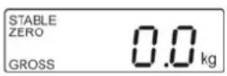
⇒ Press ON OFF, the appliance will carry out a self-test. As soon as the weight display appears, the instrument will be ready to weigh.
7.2 Switching Off
⇒ Press , the display will disappear.
7.3 Zeroing

⇒ Press →0←, zero display as well as indicator ZERO will appear.
7.4 Weighing
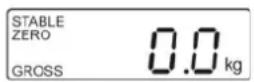
→ Place goods to be weighed on balance.
→ Wait until stability display STABLE appears.
→ Read weighing result.
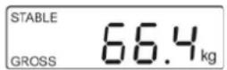
7.5 Taring
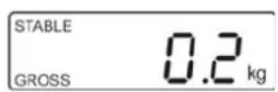
⇒ Put tare load.
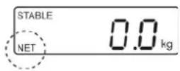
Wait for stability display „STABLE“, then press TARE. Zero display and indicator NET appear.
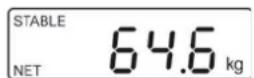
Load balance. Wait until the stability display „STABLE“ appears, then read the weighing result.
When the balance is unloaded the saved taring value is displayed with negative sign. To delete the tare value, remove load from balance and press TARE
7.5.1 Subsequent tare weight
The balance can be tared several times successively. For that select in the menu the following setting:

- Menu setting:
[F5 Str] ⇔ [Str on] (see chap. 12.4.2)
7.6 Data-Hold function
When weighing is at standstill, the weighing value will be automatically kept for 10 sec in the display until the HOLD key is actuated. By this way sufficient time remains to read the weighing value at your leisure.
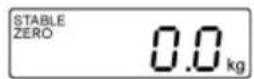
→ Start balance by pressing .

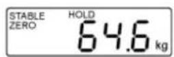
Place the items to be weighed and press, the weighing value is kept in the display.
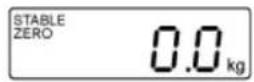
After unloading the balance, the weighing value remains displayed for approx. 10 seconds, than the balance changes automatically into the weighing mode.
The „HOLD“ symbol disappears.
7.7 See second decimal point (not verified value)
Press TARE and hold for about 2 s whilst weighed result is being shown. The second decimal place will be shown for approx. 5 s.
7.9 Calculation of the Body Mass Index
You need to know a person's body height before you can calculate the BMI for that person.
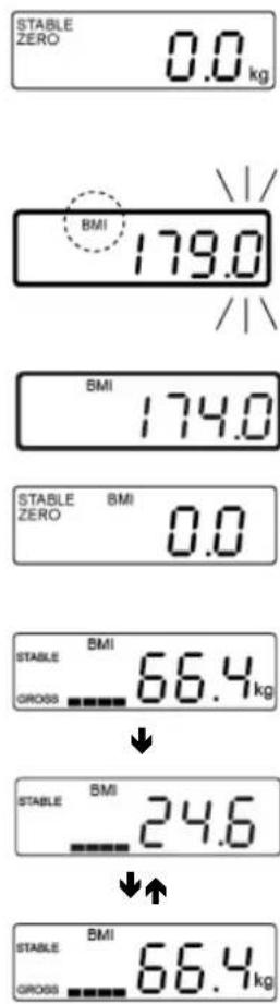
- Start balance by pressing
- Use BMI to invoke the BMI mode, the kg-display disappears, the „BMI“ symbol appears. The most recently entered body height will be shown. The active digit is flashing.
- To change, select the digit to be altered by 0 and the numerical value by
- Confirm input by
- Place the person on the center of the weighing plate the weighing value and the BMI bar graph are displayed.
- Wait for stability display, keep pressed, the BMI value of the person will be displayed.
- Use BMI to switch over the display, "Weight value", "BMI value".
⇒ For further messages press BMI repeatedly until the body size entered most recently flashes (step 2).
At step 5 appears the display, which has been used to conclude the previous measurement „Weight value,, or „BMI value“ (commutable with BMI).
→ Back to weighing mode, unload weighing plate, press BMI, the „BMI“ symbol extinguishes, the kg-display appears.
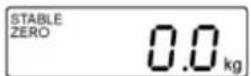

- Reliable calculation of BMI is restricted to a body height of 100 cm to 200 cm and a weight of >10 kg.
- If weighing has to take place under unsteady conditions, you can be stabilise the display by applying the Hold function.
7.9.1 Classification of BMI values
Weight classification for adults over 18 years of age using the BMI in accordance with WHO, 2000 EK IV and WHO 2004.
| Categorie BMI (kg/m) | ^2) Risk of diseases associated with overweight | |
| Underweight | < 18.5 | low |
| Normal weight | 18.5 – 24.9 | Average |
| Overweight | ≥ 25.0 | |
| Pre-adipose | 25.0 – 29.9 | A bit high |
| Adipose degree I | 30.0 – 34.9 | Increased |
| Adipose degree II | 35.0 – 39.9 | High |
| Adipose degree III | ≥ 40 | Very high |
7.10 Automatic switch-off function „AUTO OFF“
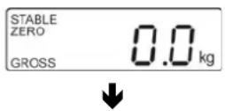
→ In weighing mode, press will be displayed.
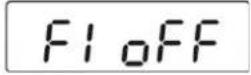
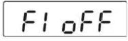
F and the first function [F1 oFF]
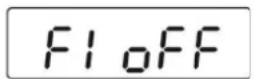
⇒ Press 📄, the current setting is displayed, e.g. [oFF 15]
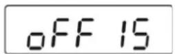
⇒ Press √↑ until the desired setting is displayed, e.g.[oFF 30]

[oFF 0]
AUTO-OFF function deactivated
[oFF 3]
AUTO-OFF after 3 minutes without changing the weight
[oFF 5]
AUTO-OFF after 5 minutes without changing the weight
[oFF 15]
AUTO-OFF after 15 minutes without changing the weight
[oFF 30]
AUTO-OFF after 30 minutes without changing the weight
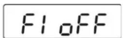
→ Confirm with

[F1 oFF] will be displayed
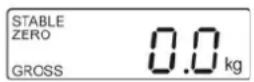
→ Return to weighing mode using

7.11 Display background illumination
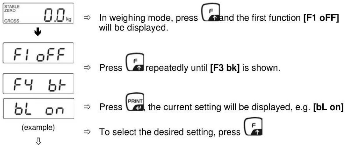
flowchart
graph TD
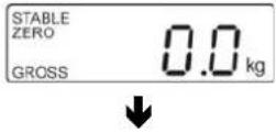
    A["STABLE ZERO GROSS 0.0 kg"] --> B["F1 oFF"]
    B --> C["F4 bF"]
    C --> D["BL on (example)"]
    D --> E["To select the desired setting, press F"]
    style A fill:#f9f,stroke:#333
    style B fill:#ccf,stroke:#333
    style C fill:#cfc,stroke:#333
    style D fill:#fcc,stroke:#333
    style E fill:#ffc,stroke:#333
| bL on | Continuous background lighting |
| bL off | Background illumination off |
| bL AU | Automatic background illumination on when weighing surface is loaded or key pressed. |

text_image
F4 6F STABLE ZERO GROSS 0.0 kg → Confirm with PRINT [F3 bk] will be displayed. → Return to weighing mode using TARE8 Data output RS 232
You can print weighing data automatically via the RS 232 interface or manually by pressing PRINT via the interface according to the setting in the menu.
This data exchange is asynchronous using ASCII - Code.
The following conditions must be met to provide successful communication between the weighing balance and the printer.
- Use a suitable cable to connect the weighing balance to the interface of the printer. Faultless operation requires an adequate KERN interface cable.
- Communication parameters (baud rate, bits and parity) of balance and printer must match. Detailed description of the interface parameters (see chap. 12.4.2, „F3 Prt“)

In a medical context only auxiliary equipment in compliance with Directive EN 60601-1 may be connected to the interface.
8.1 Pin allocation of balance output bushing:
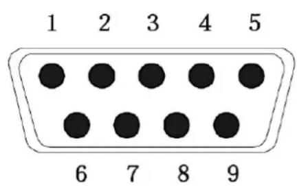
text_image
1 2 3 4 5 6 7 8 9Pin 2: TXD - output
Pin 3: RXD - input
Pin 5: GND - signal ground
8.2 Technical data
Connection 9 pin d-subminiature bushing
Pin 2 output
Pin 3 input
Pin 5 signal earth
Baud rate Optional 600/1200/2400/4800/9600
Parity 8 bits
8.3 Printer operation
| Prt\Lab | |
| 0 | 2012/08/09 11 :0060.0 kg |
| 1 | 2012/08/09 11 :0060.0 kg170.0cm20.7BMI |
| 2 | 60.0 kg |
| 3 | 60.0 kg170.0cm20.7BMI |
9 Error messages
Display
Description
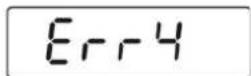
Zero range exceeded
(on start-up or when pressing the 0 key)
• There is no weighing item on the load cell
• Overload during setting to zero
- Incorrect adjusting process
- Fault on load cell
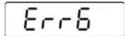
Value outside the A/D converter range
- Damaged weighing cell
- Damaged electronics
Should other error messages occur, switch balance off and then on again. If the error message remains inform manufacturer.
10 Servicing, maintenance, disposal
10.1 Clean

■ Before any maintenance, cleaning and repair work disconnect the appliance from the operating voltage.
- Do not use aggressive detergents (solvents or similar).
10.2 Servicing, maintenance
The appliance may only be opened by trained service technicians who are authorized by KERN.
Disconnect the device from mains before opening.
10.3 Disposal
Disposal of packaging and appliance must be carried out by operator according to valid national or regional law of the location where the appliance is used.
11 Instant help
In case of a fault in the program sequence, the balance should be shortly switched off. The weighing process must then be restarted from the beginning.
| Failure: | Possible causes: |
| The displayed weight does not glow. | The display unit is not switched on.The mains supply connection has been interrupted (mains cable not plugged in/faulty).Power supply interrupted.Rechargeable battery inserted incorrectly or empty.No rechargeable battery inserted. |
| The displayed weight is permanently changing | Draught/air movementTable/floor vibrationsThe load cell has contact with foreign objectsElectromagnetic fields / static charging (choose different location/switch off interfering device if possible) |
| The weighing result is obviously incorrect | The display of the balance is not at zero.Adjustment is no longer correct.Great fluctuations in temperature.The weighing system is not on even surface.Electromagnetic fields / static charging (choose different location/switch off interfering device if possible) |
Should other error messages occur, switch balance off and then on again. If the error message remains inform manufacturer.
12 Installation display unit

- Installation / configuration of a weighing system must be carried out by a well acquainted specialist with the workings of weighing balances.
12.1 Technical data
| Supply voltage: 5 V/150mA | |
| Resistance parameter | 80 - 100 Ω, max 4 items per 350 Ω load cell |
12.2 Weighing system design
The display unit is suitable for connection to any analogue load cell in compliance with the required specifications.
The following data must be established before selecting a load cell:
- Weighing balance capacity
This usually corresponds to the heaviest load to be weighed.
- Preload
This corresponds to the total weight of all parts that are to be placed on the weighing cell such as upper part of platform, weighing pan etc.
• Total zero setting range
This is composed of the start-up zero setting range ( ± 2%) and the zero setting range available to the user via the ZERO-key (2%). The total zero setting range equals therefore 4 % of the scale's capacity.
The addition of weighing scales capacity, preload and the total zero setting range give the required capacity for the weighing cell.
To avoid overloading of the weighing cell, include an additional safety margin.
- Smallest desired display division
- Verifiable, if required
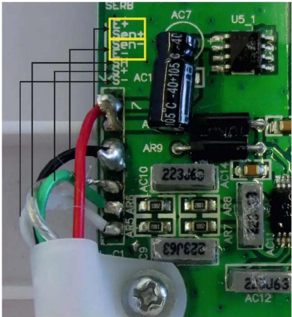
12.3 How to connect the platform
→ Disconnect the display unit from the power supply.
Solder the individual leads of the load cell cable onto the circuit board, see diagrams below.
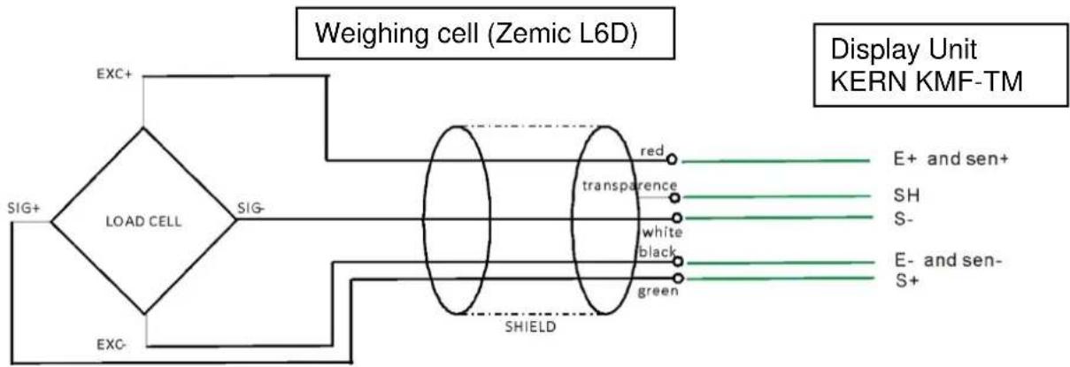
flowchart
graph LR
    A["EXC+"] --> B["LOAD CELL"]
    C["SIG+"] --> B
    D["EXC-"] --> B
    B --> E["SHIELD"]
    E --> F["red"]
    E --> G["transparence"]
    E --> H["white"]
    E --> I["black"]
    E --> J["green"]
    F --> K["E+ and sen+"]
    G --> L["SH"]
    H --> M["S-"]
    I --> N["E- and sen-"]
    J --> O["S+"]
    P["Display Unit KERN KMF-TM"] --> Q["Weighing cell (Zemic L6D)"]
text_image
SERB S+EN+ S-EN- AC7 U5_1 S+EN- AC1 105°C -40+105°C -40 AR9 223J63 AC10 1002 200T 200T 1002 C9 223J63 AR7 AR8 AC14 AC12 220J63 AC1212.4 Configure display unit

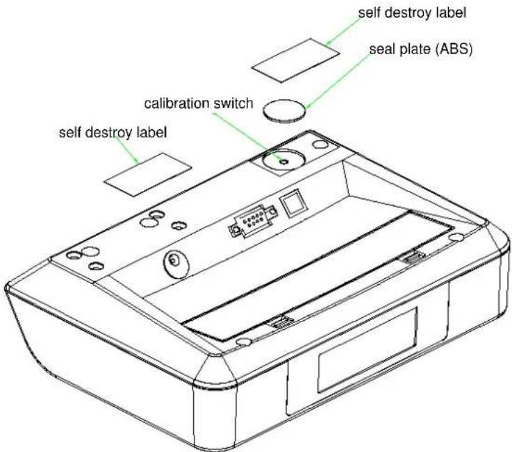
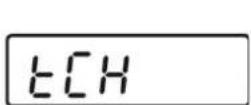
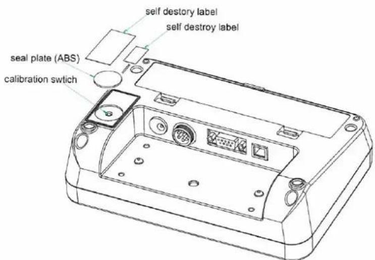
Access to service menu „tCH“ is locked in verified weighing systems. To disable the access lock, destroy the seal and actuate the adjustment switch. For position of adjustment switch, see chap. 13.
Attention:
After destruction of the seal the weighing system must be re-verified by an authorised agency and a new verification wire/seal mark fitted before it can be reused for applications subject to verification.
12.4.1 Navigation in the menu
| Call up menu | In weighing mode, press  the first function [F1oFF] will be displayed. the first function [F1oFF] will be displayed. |
| Select function | With help of  the individual functions can be selected one after the other. the individual functions can be selected one after the other. |
| Change settings | Confirm selected function by  the current setting will be displayed. Select desired setting by the current setting will be displayed. Select desired setting by  confirm with balance returns to the menu. confirm with balance returns to the menu. |
| Exit menu/Return to weighing mode | Press [TARE], the balance will return to weighing mode. |
12.4.2 Menu overview
| Function | Adjustment | Description | |
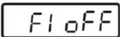 Automatic cutoutAuto Off Automatic cutoutAuto Off | oFF 0* | Automatic shutdown off | |
| oFF 3 | Automatic shutdown after 3 sec | ||
| oFF 5 | Automatic shutdown after 5 sec | ||
| oFF 15 | Automatic shutdown after 15 sec | ||
| oFF 30 | Automatic shutdown after 30 sec | ||
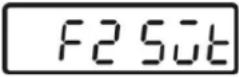 | oFF* | Not documented | |
| Prt | |||
| Pr ACC | |||
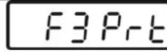 Interface parameter Interface parameter | 1. RS-232 modeSelect desired mode by  n confirm with . n confirm with .  | ||
| P Prt | Weight will be added to summation memory and printed after pressing PRINT | ||
| P Cont | Continuous data output | ||
| Series | Not documented | ||
| ASK | Remote control instructions:W: Send all weighing detailsS: Send stable weight valueT: TaringZ: Zeroing | ||
| P cnt 2 | Not documented | ||
| P Stab | Automatic data output of stable weighing values | ||
| P Auto | Weighed result will be added automatically to summation memory and issued | ||
| 2. Baud rateThe currently set baud rate (b xxx) will be shown after the RS-232 mode was confirmed. Select desired Baudrate by pressingF and confirm by pressing PRINTAvailable Baud rate: 600, 1200, 2400, 4800, 96003. Data output format(P Prt, P Auto, P Cont settings only)the currently set data output format will be shown after thebaud rate was confirmed. Select desired format by [F] and confirm with [PRINT] | |||
| only with setting P Prt, P | Prt 0-7 | Data output format, see chap. 8.3 | |
| Lab 0-3 | |||
| Only when set P Cont | Cont 1 Default | ||
| Cont 2 | Not documented | ||
| Cont 3 | Not documented | ||
| 4. Printer typeAfter the data output format has been confirmed, the currently set printer type will be displayed.Mit Select the desired printer type by pressing [F] and confirm by pressing [PRINT]KERN Standard printer settingLP -50 Not documentedtPUP Not documented | |||
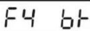 Background illumination of display Background illumination of display | bl on | Back lighting for display on | |
| bl oFF | Display background illumination off | ||
| bl AU* | Backlighting for display will come on automatically as soon as the weighing scale is operated. | ||
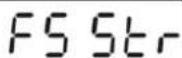 Subsequent tare value locked in devices with type approval certificate. Subsequent tare value locked in devices with type approval certificate. | Str on | Following tare ON | |
| Str oFF* | Following tare OFF | ||
 Service menu Service menu | Pin | Password Input: press  , ,  , ,  subsequently. subsequently. |
| Operate adjustment switch; for position see chap.13 | ||
 Display speed Display speed | 15* | Not documented |
| 30 | ||
| 60 | ||
| 7.5 | ||
 Configuration Configuration | desc | Position decimal point,selectable 0, 0.0, 0.00, 0.000, 0.0000 |
| Inc | Readability,selectable div 1, div 2, div 5, div 10, div 20, div 50 | |
| cap | Balance capacity (/max) | |
| cal | Adjustment, see chap. 14 | |
 | tri* | Not documented |
| CoUnt | Not documented | |
| rESEt | Reset weighing scale to factory setting | |
| SEtGrA | Not documented | |
* default setting
12.4.3 Carry out configuration
  | In weighing mode, press repeatedly until [tCH] appears. |
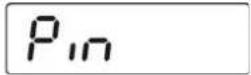
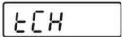 | Press [Pin] is displayed For the access to the service menu press the adjustment switch, position see chap. 13. |
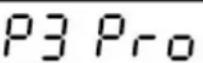
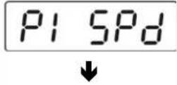
 | Press and one after the other, [P1 SPd] will appear |
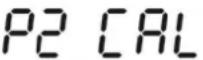
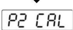
 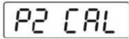 | Press [P2 CAL] will be displayed Press [DESC] is displayed |
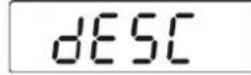 | Press currently set position of the decimal dot is displayed. Press to select the desired setting. Selectable 0, 0.0, 0.00, 0.000, 0.0000. Confirm input with balance returns to the menu. Use to select the next menu item [inC]. |
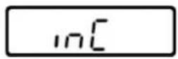 | →Press  , the currently set readability is displayed.Press , the currently set readability is displayed.Press  select the desired setting.Select select the desired setting.Select  div 1, div 2, div 5, div 10, div 20, div 50→Confir div 1, div 2, div 5, div 10, div 20, div 50→Confir  , the balance returns to the menu.→Use , the balance returns to the menu.→Use  to select the next menu item [CAP]. to select the next menu item [CAP]. |
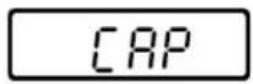 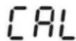 | →Press  , the currently set capacity (Max) is displayed.Use th , the currently set capacity (Max) is displayed.Use th  vigation keys to select the desired settingUse vigation keys to select the desired settingUse  elect the digit to be changed, the active digitflashe elect the digit to be changed, the active digitflashe  Use Increase numeric value.→Confir Use Increase numeric value.→Confir  , the balance returns to the menu.→Use , the balance returns to the menu.→Use  to select the next menu item [CAL].Adjustment is required after entering configuration data!⇒ Confirm with to select the next menu item [CAL].Adjustment is required after entering configuration data!⇒ Confirm with  [UnloAd] appears [UnloAd] appears |
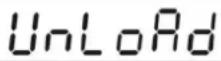 | ⇒ Ensure that there are no objects on the weighing pan.⇒ Wait for stability display "STABLE", then confirm with  |
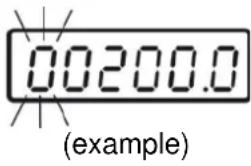 | ⇒ The size of the currently set adjustment weight will be displayed.To change, select the digit to be altered by  I the numerical value by ⇒ Confirm with I the numerical value by ⇒ Confirm with  [LoAd] appears. [LoAd] appears. |
 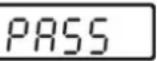 | ⇒ Place the adjustment weight carefully⇒ Wait until stability display „STABLE“ appears⇒ Confirm with  [PASS] is displayed. [PASS] is displayed. |
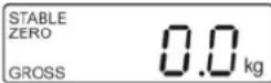 | After the adjustment the balance will carry out a self-test. Remove adjusting weight during selftest, balance will return into weighing mode automatically.An adjusting error or incorrect adjusting weight will be indicated by the error message; repeat adjustment procedure.An adjusting error or incorrect adjustment weight will generate an error message („Err 4“), repeat the adjustment process. |
13 Verification
General introduction:
According to EU directive 2009/23/EC balances must be officially verified if they are used as follows (legally controlled area):
a) For commercial transactions if the price of goods is determined by weighing.
b) For the production of medicines in pharmacies as well as for analyses in the medical and pharmaceutical laboratory.
c) For official purposes
d) For manufacturing final packages
In cases of doubt, please contact your local trade in standard.
Verification notes:
An EU type approval exists for balances described in their technical data as verifiable. If a balance is used where obligation to verify exists as described above, it must be verified and re-verified at regular intervals.
Re-verification of a balance is carried out according to the respective national regulations. For verification validity period, s. chap. 15.1.
The legal regulation of the country where the balance is used must be observed!
Verification of the balance is invalid without the seal.
The seal marks attached on balances with type approval point out that the balance may only be opened and serviced by trained and authorised specialist staff. If the seal mark is destroyed, verification looses its validity. Please observe all national laws and legal regulations. In Germany a reverification will be necessary.
Balances with obligation to verify must be taken out of operation if:
- The weighing result of the balance is outside the error limit. Therefore, in regular intervals load balance with known test weight (ca. 1/3 of the max. load) and compare with displayed value.
• The reverification deadline has been exceeded.
Position adjustment switch and seals:
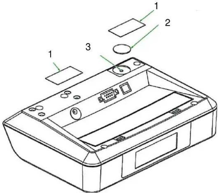
text_image
Technical diagram of a printer with labeled parts including ports, connectors, and display screen- Self-destroying seal mark
- Cover
- Adjustment switch
14 Adjustment
As the acceleration value due to gravity is not the same at every location on earth, each display unit with connected load cell must be coordinated - in compliance with the underlying physical weighing principle - to the existing acceleration due to gravity at its place of location (only if the weighing system has not already been adjusted to the location in the factory). This adjustment process must be carried out for the first commissioning, after each change of location as well as in case of fluctuating environment temperature. To receive accurate measuring values it is also recommended to adjust the display unit periodically in weighing operation.

- Prepare the required adjustment weight. The weight to be used depends on the capacity of the scale. Carry out adjustment as near as possible to the scale's maximum weight. Info about test weights can be found on the Internet at: http://www.kern-sohn.com.
- Observe stable environmental conditions. Stabilisation requires a certain warm-up time.

Access to service menu „tCH“ is locked in verified balances.
To disable the access lock, destroy the seal and actuate the adjustment switch. Position of the adjustment switch see chap. 13.
Attention:
After destruction of the seal the weighing system must be re-verified by an authorised agency and a new verification wire/seal mark fitted before it can be reused for applications subject to verification.
Procedure:
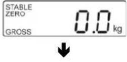  | In weighing mode, press repeatedly until [tCH] appears. |
 | Press [Pin] is displayed |
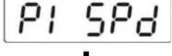
 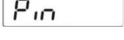 | Press [TARE and BMI one after the other, [P1 SPd] will appear |
 | Press [P2 CAL" will be displayedOperate adjustment switch; for position see chap.13 |
  | |
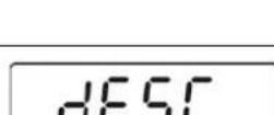  | Press [dESC] is displayed |
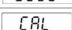
 | Press [repeatedly until [CAL] will be displayed.Confirm with [UnloAd] appears |
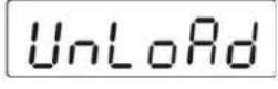   (example) (example) | Ensure that there are no objects on the weighing pan.Wait for stability display "STABLE", then confirm with |
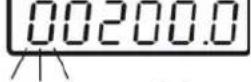
| The size of the currently set adjustment weight will be displayed. The active digit is flashing.To change, select the digit to be altered by and thenumerical value by | |
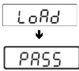 | → Place the adjustment weight carefully→ Wait until stability display „STABLE“ appears→ Confirm with [PASS] is displayed. |
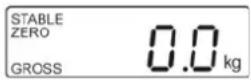 | After the adjustment the balance will carry out a self-test. Remove adjusting weight during selftest, balance will return into weighing mode automatically.An adjusting error or incorrect adjusting weight will be indicated by the error message; repeat adjustment procedure.An adjusting error or incorrect adjustment weight will generate an error message („Err 4“), repeat the adjustment process. |
15 Enclosure
Type Approval Certificate when using as weighing system KERN MPD
EC Type-Approval Certificate
No. DK 0199.365 Revision 1
MBC / MPE / MPD / MPC / MCC
NON-AUTOMATIC WEIGHING INSTRUMENT
Issued by DELTA Danish Electronics, Light & Acoustics EU - Notified Body No. 0199
In accordance with the requirements for the non-automatic weighing instrument of EC Council Directive 2009/23/EC.
Issued to Kern & Sohn GmbH Ziegelei 1 D-72336 Balingen GERMANY
In respect of Non-automatic weighing instrument designated MBC / MPE / MPD / MPC / MCC with variants of modules of load receptors, load cells and peripheral equipment. Accuracy class III, single interval or multi-range (2 ranges) Maximum capacity, Max: From 6 kg up to 250 kg Verification scale interval: e_i = Max_i/n_i Maximum number of verification scale intervals: n_i = 3000 (however, dependent on environment and the composition of the modules). Variants of modules and conditions for the composition of the modules are set out in the annex.
The conformity with the essential requirements in annex 1 of the Directive is met by the application of the European Standard EN 45501:1992/AC:1993.
The principal characteristics and approval conditions are set out in the descriptive annex to this certificate.
The annex comprises 14 pages.
Issued on 2012-12-18 Valid until 2022-10-11

DELTA
Venlighedsvej 4
2970 Hørsholm
Denmark
Tel. (+45) 72 19 40 00
Fax (+45) 72 19 40 01
www.delta.dk
VAT No. DK 12275110
Descriptive annex
| Contents | Page | |
| 1. | Name and type of instrument | 2 |
| 2. | Description of the construction and function | 2 |
| 2.1 | Construction | 2 |
| 2.2 | Function | 3 |
| 3. | Technical data | 5 |
| 3.1 | Scales | 5 |
| 3.2 | Indicators | 5 |
| 3.3 | Load cells | 6 |
| 3.4 | Composition of modules | 6 |
| 3.5 | Documents | 6 |
| 4. | Interfaces and peripheral equipment | 6 |
| 4.1 | RS-232 | 6 |
| 4.2 | USB | 6 |
| 4.3 | Peripheral equipment | 6 |
| 5. | Approval conditions | 7 |
| 5.1 | Measurement functions other than non-automatic functions | 7 |
| 5.2 | Compatibility of modules | 7 |
| 6. | Special conditions for verification | 7 |
| 6.1 | Composition of modules | 7 |
| 7. | Securing and location of seals and verification marks | 7 |
| 7.1 | Securing and sealing | 7 |
| 7.2 | Verification marks | 8 |
| 8. | Location of CE mark of conformity and inscriptions | 8 |
| 8.1 | Scale | 8 |
| 9. | Pictures | 9 |
1. Name and type of instrument
The weighing instruments designated MBC, MPE, MPD, MPC and MCC are self-indicating computing scales of Class III with single interval or multi-range (2 ranges), an external AC mains adapter, and an internal rechargeable battery (optional).
The scales are intended for medical weighing.
The scales consist of analogue to digital conversion, microprocessor control, power supply, keyboard, non-volatile memory for storage of calibration and weight data, and a weight display contained within a single enclosure, however, the display part is placed on a post.
2. Description of the construction and function
2.1 Construction
Enclosure
The indicator part of the scales is housed in an ABS enclosure approximately 200 mm wide, 125 mm deep and 55 mm high.
There are two models of the housing depending on whether the indicator is placed on a pole (B) or not (A).
Keyboard
The keyboard of the scales contains 6 or 7 membrane keys - including On/Off - used to control the functions of the scale, except model MPD, which has no keyboard.
Display
The display of the scales comprises of a 6 digits 7-segment LCD display with backlight and appropriate status indicators.
Electronics
All the instruments use the same printed circuit board, a main board, which also includes the display components.
Models
| Scale model | Product name | Max | e. | Load cell | E_max | Note |
| MBC | Baby scale | 20 kg | 10 g | L6D | 30 kg | Without height measurement |
| With MBC-A01 height measure | ||||||
| MBC | Baby scale | 6 kg/15 kg | 2 g/5 g | L6D | 20 kg | Without height measurement |
| With MBC-A01 height measure | ||||||
| MPE | Height scale | 250 kg | 100 g | L6E | 300 kg | With height measurement |
| Without height measurement | ||||||
| MPD | Step on scale | 250 kg | 100 g | L6E | 300 kg | Step on, without keys |
| MPC | Wall mount personal scale | 250 kg | 100 g | L6E | 300 kg | Wall mount, without pole |
| MCC | Wheel chair scale | 250 kg | 100 g | L6E3 | 300 kg | Wheel chair scale |
The model names may be followed by alphanumeric characters for technical, legal or commercial characterization of the instrument.
Other models are allowed, if their technical data are in accordance with Chapter 3 and they fulfil the requirements in Sections 3.1 and 5.4.
2.2 Function
The weight indicating instruments are microcontroller based electronic scales with a digital display used to show weight and for some models height and BMI index depending on the current operating mode. The instruments are available for operation from mains at 230 VAC 50 Hz using an external AC/DC adapter or from an internal battery consisting of 6 rechargeable "AA" batteries.
The primary functions provided are detailed below.
2.2.1 Power-up
On power-up, the weight indicator will display of the software version for 2 seconds and then perform a display test. After that it will automatically establish the current weight as a new zero reference.
2.2.2 Test function
On power-up, the weight indicator will test all memory functions followed by a display test. The display test consists of counting down the numeric digits from 9 to 0 and turning all the indicators on.
2.2.3 Display range
The weight indicators will display weight from -Max (tare function) to Max +9e (gross weight).
2.2.4 Zero-setting
Pressing the ZERO key causes a new zero reference to be established and ZERO annunciator to turn on, indicating that the display is at the centre of zero.
Zero-setting range: ±2% of Max.
Initial zero-setting range: ≤ ±10% of Max.
Zero-setting is only possible when the displayed weight is stable.
2.2.5 Zero-tracking
The indicators are equipped with a zero-tracking feature which operates over a range of ± 2% of Max and only when the indicator is at gross zero and there is no motion in the weight display.
2.2.6 Tare
The instrument models are provided with a semi-automatic subtractive tare.
2.2.6.1 Semi-automatic tare
Pressing the TARE key will take the current weight as the tare weight. The weight display will automatically change to the net weight display mode and turn on the NET annunciator.
Consecutive tare operations are possible on all models.
The tare value can be cleared by pressing the TARE key, when there is no load on the load receptor.
This tare entry cannot take place if the displayed weight is instable.
2.2.6.2 Drinking function (only model MBC)
The drinking function is a special tare function on the baby scale models.
Pressing the Ⓜ (weigh before drink) button will turn the "DRINK" indicator and remember the
current baby weight as a tare value.
When the baby after having been drinking is placed on the load receptor again, a press on the (weigh after drink) button will show the weight change of the baby between the two weighings.
Pressing the ⏻ key a second time will turn the drink function off.
2.2.7 HOLD
Pressing the HOLD key will turn on the "HOLD" indicator and the display will show "----" until a load has been placed on the pan and the weight signal is stable, at which time the display will show the detected stable weight. This weight will be locked in the weight display until 10 seconds after the load has been removed or the "HOLD" key has been pressed a second time. Either of them will turn the "HOLD" indicator off and unlock the weight display.
This feature is not to be used in trade applications, but may be convenient in clinical or health care weighing applications.
2.2.8 BMI (only models MPC. MPE and MCC)
The BMI key is used to access the Body Mass Index feature of the indicator. This allows the operator to enter the height of the person on the load receptor. When height is displayed the HEIGHT annunciator is on.
Pressing the F" key will calculate and display the Body Mass Index (BMI). Display of the BMI is indicated by turning the BMI annunciator on.
Pressing the BMI key again will return the scale to normal weighing mode.
2.2.9 Backlight
Pressing the menu key "F" gives access to set the backlight between Off (always off), On (always on) and Auto (on for a period of time after a change in weight).
2.2.10 Operator information messages
The weight display can show a number of general and diagnostic messages, which are described in detail in the User's Guide.
2.2.11 Software version
The software revision level is displayed during the power-up sequence of the instrument.
The approved software versions are,
| MBC: | v1.10 |
| MPE: | v3.09 |
| MPD: | v3.08 |
| MCC/MPC: | v5.09 |
2.2.12 Battery operation
The scale can be operated from an internal battery. This battery consists of 6 "AA" size rechargeable batteries.
The weight indicator contains the circuitry necessary to recharge the battery when the indicator is connected to the mains power.
3. Technical data
3.1 Scales
The scales have the following characteristics:
| Accuracy class: | III |
| Weighing range: | Single interval or multi-range (2 ranges) |
| Maximum number of Verification Scale Intervals: | ≤3000 pr. interval/range |
| Maximum capacity (Max): | from 6 kg to 250 kg |
| Verification Scale Interval: | e≥2 g |
| Maximum tare effect: | -Max |
| Mains power supply: | 9-12 VDC / 230 VAC, 50 Hz using external adapter |
| Operational temperature: | -10°C to +40 °C |
| Peripheral interface: | Set out in section 4 |
3.2 Indicators
The indicators have the following characteristics:
| Accuracy class: | III and IIIISingle-interval, multi-range (2 ranges) or multi-interval (2 partial intervals) |
| Weighing range: | |
| Maximum number of VerificationScale Intervals: | ≤ 6000 (class III), ≤ 1000 (class III) for single-interval≤ 3000 (class III), ≤ 1000 (class III) for multi-range and multi-interval |
| Maximum tare effect: | -Max within display limits |
| Fractional factor: | p'i = 0.5 |
| Minimum input voltage per VSI: | 1 μV |
| Excitation voltage: | 5 VDC |
| Circuit for remote sense: | present on the model with 7-terminal connector |
| Minimum input impedance: | 87 ohm |
| Maximum input impedance: | 1600 ohm |
| Mains power supply: | 9 – 12 VDC / 230 VAC, 50 Hz using external adapter |
| Operational temperature: | -10 °C to +40 °C |
| Peripheral interface: | Set out in section 4 |
3.2.1 Connecting cable between the indicator and load cell / junction box for load cell(s)
3.2.1.1 4-wire system
Cable between indicator and load cell(s): 4 wires (no sense), shielded Maximum length: the certified length of the load cell cable, which shall be connected directly to the indicator.
3.2.1.2 6-wire system
Only to be used for indicator model with a 7-terminal connector for load cell.
Cable between indicator and junction box: 6 wires, shielded
Maximum length: 227 m / mm ^4
3.3 Load cells
3.3.1 ZEMIC L6D and L6E load cells
The ZEMIC L6D C3 load cell and ZEMIC L6E C3 load cell shall be selected according to the table of models in section 2.1.
3.3.2 General acceptance of modules
Any load cell(s) may be used for instruments under this certificate of type approval provided the following conditions are met:
1) A test certificate (EN 45501) or OIML Certificate of Conformity (R60) respectively issued for the load cell by a Notified Body responsible for type examination under the Directive 2009/23/EC.
2) The certificate contains the load cell types and the necessary load cell data required for the manufacturer's declaration of compatibility of modules (WELMEC 2, Issue 5, 2009), and any particular installation requirements). A load cell marked NH is allowed only if humidity testing to EN 45501 has been conducted on this load cell.
3) The compatibility of load cells and indicator is established by the manufacturer by means of the compatibility of modules form, contained in the above WELMEC 2 document, or the like, at the time of EC verification or declaration of EC conformity of type.
4) The load transmission must conform to one of the examples shown in the WELMEC 2.4 Guide for load cells.
3.4 Composition of modules
In case of composition of modules, EN 45501 paragraph 3.5 and 4.12 shall be satisfied.
3.5 Documents
The documents filed at DELTA (reference No. T202965) are valid for the weighing instruments described here.
4. Interfaces and peripheral equipment
4.1 RS-232
The scales may be equipped with a RS-232 interface for connection to peripheral equipment. This interface is characterised as a "Protective interface" according to paragraph 8.4 in the Directive.
4.2 USB
The height scale (MPE), the step on scale (MPD and the personal scale (MPC) may be equipped with an USB interface for connection to peripheral equipment. This interface is characterised as a “Protective interface” according to paragraph 8.4 in the Directive.
The USB cable used for connection shall be less than 3 m long.
4.3 Peripheral equipment
The instrument may be connected to any simple printer with a CE mark of conformity by a screened cable.
5. Approval conditions
5.1 Measurement functions other than non-automatic functions
Measurement functions that will enable the use of the instrument as an automatic weighing instrument are not covered by this type approval.
5.2 Compatibility of modules
In case of composition of modules, WELMEC 2 (Issue 5) 2009, paragraph 11 shall be satisfied.
6. Special conditions for verification
6.1 Composition of modules
The environmental conditions should be taken into consideration by the composition of modules for a complete weighing instrument, for example instruments with load receptors placed outdoors and having no special protection against the weather.
The composition of modules shall agree with Section 5.2.
7. Securing and location of seals and verification marks
7.1 Securing and sealing
Seals shall bear the verification mark of a notified body or alternative mark of the manufacturer according to ANNEX II, section 2.3 of the Directive 2009/23/EC.
7.1.1 Indicator
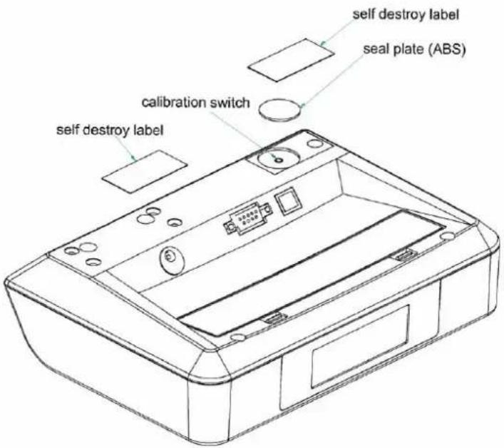
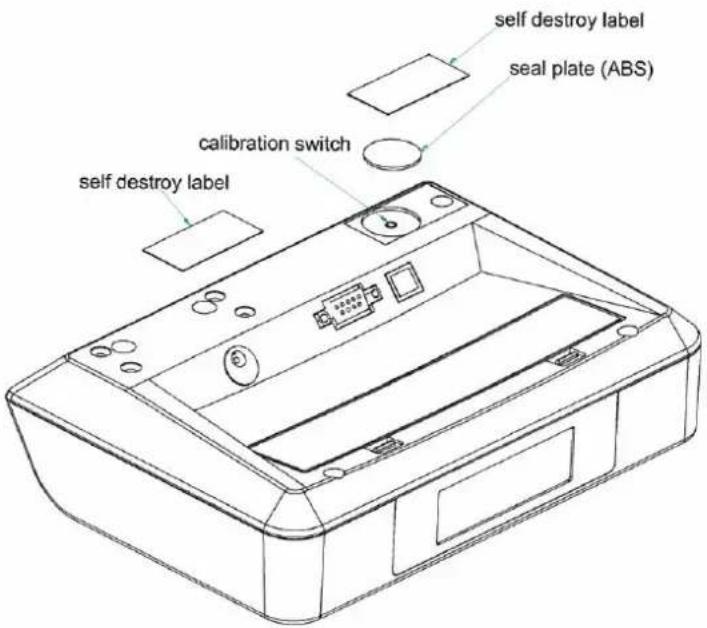
Access to the configuration and calibration facility is achieved by pressing and releasing the internal calibration switch (accessed through a hole on the rear side of the indicator). This is accomplished by removing the seal from the rear of the indicator enclosure, remove the protecting cover plate, and pressing the calibration switch button.
Sealing of the access to the switch is accomplished by placing the cover plate over the switch and then sealing this plate with a sticker.
Sealing of the cover of the enclosure - to secure the electronics against dismantling/adjustment - is accomplished with a brittle plastic sticker. The sticker is placed so access to one of the screws of the enclosure is prohibited.
7.1.2 Indicator - load cell connector - load receptor
Securing of the indicator, load receptor and load cell combined is done in one of the following ways:
- Load cell cable is connected directly on the main board of indicator(no connector)
• Sealing of the load cell connector with the indicator by a lead wire seal - Inserting the serial number of the load receptor as part of the principal inscriptions contained on the indicator identification label
• The load receptor bears the serial number of the indicator on its data plate.
7.1.3 Peripheral interfaces
All peripheral interfaces are “protective”; they neither allow manipulation with weighing data or legal setup, nor change of the performance of the weighing instrument in any way that would alter the legality of the weighing.
7.2 Verification marks
7.2.1 Indicator
A green M-sticker shall be placed next to the CE mark on the inscription plate.
The sticker with verification marks may be placed on or next to the inscription plate or on the front of the indicator.
7.2.2 Printers used for legal transactions
Printers covered by this type approval and other printers according to Section 4.2, which have been subject to the conformity assessment procedure, shall not bear a separate green M-sticker in order to be used for legal transactions.
8. Location of CE mark of conformity and inscriptions
8.1 Scale
8.1.1 CE mark
A sticker with the CE mark of conformity and year of production is located on the identification plate which is located on the enclosure.
8.1.2 Inscriptions
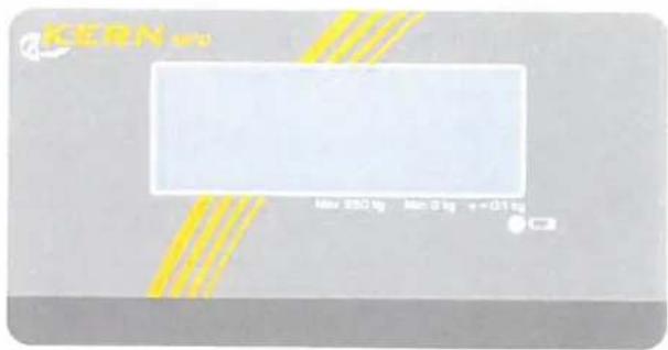
Located on the front panel overlay of the indicator:
• Max, Min, e =
On the inscription plate:
- Manufacturer's name and/or trademark, model no., serial no., type-approval certificate no., Max, Min, e =, accuracy class, temperature range, electrical data and other inscriptions.
8.1.2.1 Load receptors
On a data plate:
• Manufacturer's name, type, serial number, capacity
Left to the manufacturer choice as provided in Section 7.1.2:
- Serial no. of the indicator
8.1.3 Printers used for legal transactions
A printer connected to the scale shall according to Sections 4.2 and 5.3 not bear a separate green M-sticker in order to be used for legal transactions.
9. Pictures
text_image
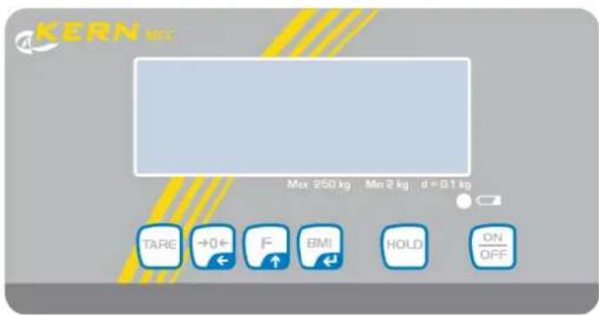
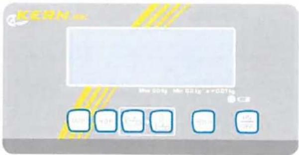
KERN Mn 201g Mr 201g x+001g 0.00 0.00 0.00 0.00 0.00 0.00 ±0.00Figure 1 Front layout of indicator on MBC
natural_image
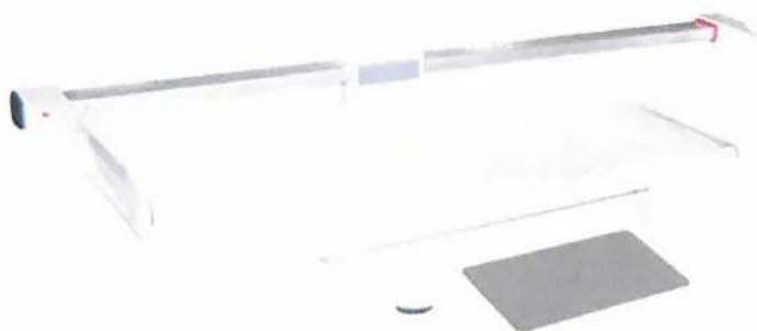
Exterior view of a modern office building (no signage)Figure 2 MBC scale with MBC-A01 (height measure).
natural_image
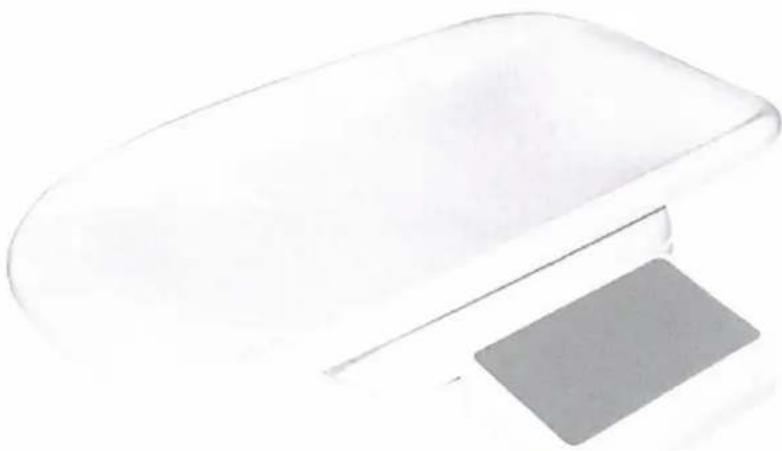
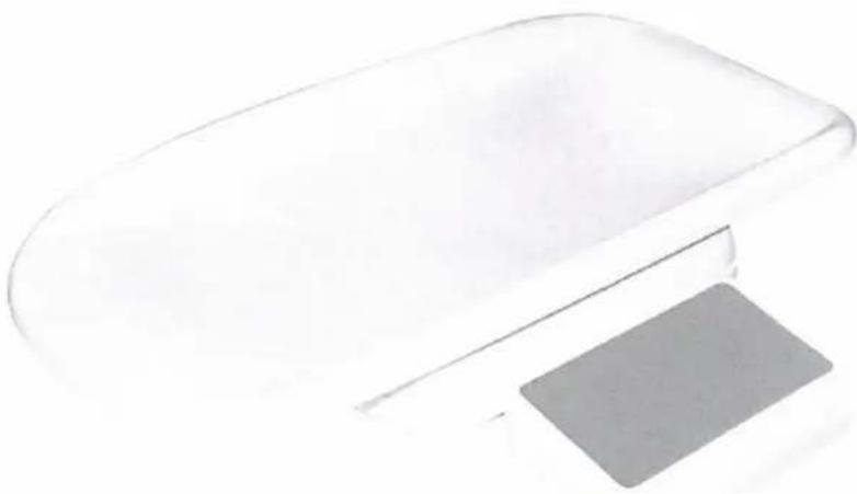
Simple line drawing of a flat rectangular object with a gray rectangular base, no text or symbols present.Figure 3 MBC scale.
text_image
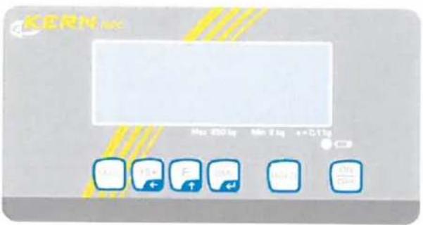
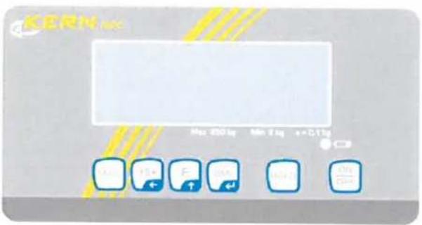
KERN Max 200.1q Min 8.1q s=0.11p OK OFF F ON ON ON ONFigure 4 Front layout of indicator on MPC
natural_image
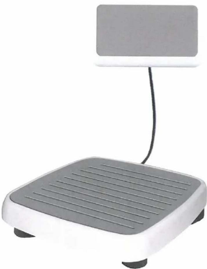
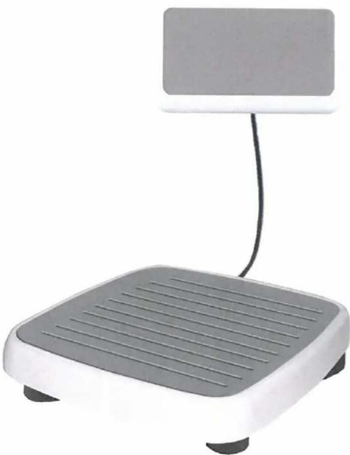
Exterior view of a gray and white electronic device with a vertical screen above it (no text or symbols visible)Figure 5 MPC personal scale with wall mounted indicator.
text_image
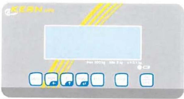
KERN 400 kg 100 g 2.50 kgFigure 6 Front layout of indicator on MPE
natural_image
Minimalist illustration of a vertical pole and two rectangular objects on a plain background (no text or symbols)
natural_image
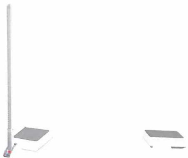
Simple gray square object with two small dark curved shapes at the bottom (no text or symbols)Figure 7 MPE personal scale with pole and height measure.

natural_image
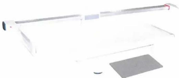
White rectangular electronic device with a flat top and two small feet at the base (no visible text or symbols)Figure 8 MPE personal scale with pole.
text_image
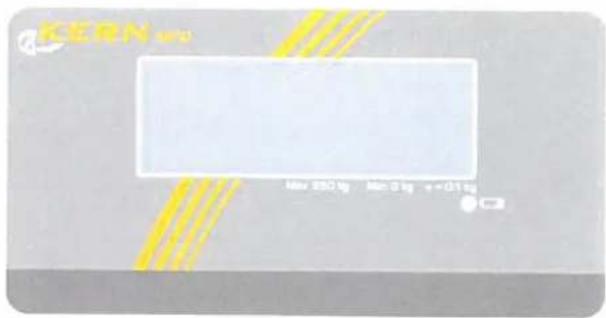
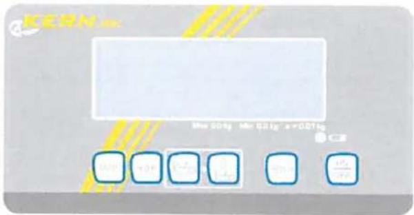
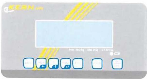
KERN Max 250 kg Max 3 kg +0.1 kgFigure 9 Front layout of indicator on MPD
natural_image
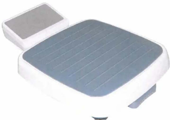
Exterior view of a modern office building (no signage)Figure 10 MPD personal scale.
text_image
self destroy label seal plate (ABS) calibration switch self destroy labelFigure 13 Sealing of indicator for model MPE.

text_image
self destory label self destroy label seal plate (ABS) calibration switchFigure 14 Sealing of indicator for model MBC / MPD / MPC / MCC.

KERN KMF-TM
Version 1.0 06/2013
text_image
Technical diagram of a device with labeled components including ports, connectors, and parts numbered 1, 2, and 3.| Contents | Page | |
| 1. | Name and type of instrument | 2 |
| 2. | Description of the construction and function | 2 |
| 2.1 | Construction | 2 |
| 2.2 | Function | 3 |
| 3. | Technical data | 5 |
| 3.1 | Scales | 5 |
| 3.2 | Indicators | 5 |
| 3.3 | Load cells | 6 |
| 3.4 | Composition of modules | 6 |
| 3.5 | Documents | 6 |
| 4. | Interfaces and peripheral equipment | 6 |
| 4.1 | RS-232 | 6 |
| 4.2 | USB | 6 |
| 4.3 | Peripheral equipment | 6 |
| 5. | Approval conditions | 7 |
| 5.1 | Measurement functions other than non-automatic functions | 7 |
| 5.2 | Compatibility of modules | 7 |
| 6. | Special conditions for verification | 7 |
| 6.1 | Composition of modules | 7 |
| 7. | Securing and location of seals and verification marks | 7 |
| 7.1 | Securing and sealing | 7 |
| 7.2 | Verification marks | 8 |
| 8. | Location of CE mark of conformity and inscriptions | 8 |
| 8.1 | Scale | 8 |
| 9. | Pictures | 9 |
1. Name and type of instrument
The weighing instruments designated MBC, MPE, MPD, MPC and MCC are self-indicating computing scales of Class III with single interval or multi-range (2 ranges), an external AC mains adapter, and an internal rechargeable battery (optional).
The scales are intended for medical weighing.
The scales consist of analogue to digital conversion, microprocessor control, power supply, keyboard, non-volatile memory for storage of calibration and weight data, and a weight display contained within a single enclosure, however, the display part is placed on a post.
2. Description of the construction and function
2.1 Construction
Enclosure
The indicator part of the scales is housed in an ABS enclosure approximately 200 mm wide, 125 mm deep and 55 mm high.
There are two models of the housing depending on whether the indicator is placed on a pole (B) or not (A).
Keyboard
The keyboard of the scales contains 6 or 7 membrane keys - including On/Off - used to control the functions of the scale, except model MPD, which has no keyboard.
Display
The display of the scales comprises of a 6 digits 7-segment LCD display with backlight and appropriate status indicators.
Electronics
All the instruments use the same printed circuit board, a main board, which also includes the display components.
Models
| Scale model | Product name | Max | e. | Load cell | E_max | Note |
| MBC | Baby scale | 20 kg | 10 g | L6D | 30 kg | Without height measurement |
| With MBC-A01 height measure | ||||||
| MBC | Baby scale | 6 kg/15 kg | 2 g/5 g | L6D | 20 kg | Without height measurement |
| With MBC-A01 height measure | ||||||
| MPE | Height scale | 250 kg | 100 g | L6E | 300 kg | With height measurement |
| Without height measurement | ||||||
| MPD | Step on scale | 250 kg | 100 g | L6E | 300 kg | Step on, without keys |
| MPC | Wall mount personal scale | 250 kg | 100 g | L6E | 300 kg | Wall mount, without pole |
| MCC | Wheel chair scale | 250 kg | 100 g | L6E3 | 300 kg | Wheel chair scale |
The model names may be followed by alphanumeric characters for technical, legal or commercial characterization of the instrument.
Other models are allowed, if their technical data are in accordance with Chapter 3 and they fulfil the requirements in Sections 3.1 and 5.4.
2.2 Function
The weight indicating instruments are microcontroller based electronic scales with a digital display used to show weight and for some models height and BMI index depending on the current operating mode. The instruments are available for operation from mains at 230 VAC 50 Hz using an external AC/DC adapter or from an internal battery consisting of 6 rechargeable "AA" batteries.
The primary functions provided are detailed below.
2.2.1 Power-up
On power-up, the weight indicator will display of the software version for 2 seconds and then perform a display test. After that it will automatically establish the current weight as a new zero reference.
2.2.2 Test function
On power-up, the weight indicator will test all memory functions followed by a display test. The display test consists of counting down the numeric digits from 9 to 0 and turning all the indicators on.
2.2.3 Display range
The weight indicators will display weight from -Max (tare function) to Max +9e (gross weight).
2.2.4 Zero-setting
Pressing the ZERO key causes a new zero reference to be established and ZERO annunciator to turn on, indicating that the display is at the centre of zero.
Zero-setting range: ±2% of Max.
Initial zero-setting range: ≤ ±10% of Max.
Zero-setting is only possible when the displayed weight is stable.
2.2.5 Zero-tracking
The indicators are equipped with a zero-tracking feature which operates over a range of ± 2% of Max and only when the indicator is at gross zero and there is no motion in the weight display.
2.2.6 Tare
The instrument models are provided with a semi-automatic subtractive tare.
2.2.6.1 Semi-automatic tare
Pressing the TARE key will take the current weight as the tare weight. The weight display will automatically change to the net weight display mode and turn on the NET annunciator.
Consecutive tare operations are possible on all models.
The tare value can be cleared by pressing the TARE key, when there is no load on the load receptor.
This tare entry cannot take place if the displayed weight is instable.
2.2.6.2 Drinking function (only model MBC)
The drinking function is a special tare function on the baby scale models.
Pressing the Ⓜ (weigh before drink) button will turn the "DRINK" indicator and remember the
current baby weight as a tare value.
When the baby after having been drinking is placed on the load receptor again, a press on the (weigh after drink) button will show the weight change of the baby between the two weighings.
Pressing the ⏻ key a second time will turn the drink function off.
2.2.7 HOLD
Pressing the HOLD key will turn on the "HOLD" indicator and the display will show "----" until a load has been placed on the pan and the weight signal is stable, at which time the display will show the detected stable weight. This weight will be locked in the weight display until 10 seconds after the load has been removed or the "HOLD" key has been pressed a second time. Either of them will turn the "HOLD" indicator off and unlock the weight display.
This feature is not to be used in trade applications, but may be convenient in clinical or health care weighing applications.
2.2.8 BMI (only models MPC. MPE and MCC)
The BMI key is used to access the Body Mass Index feature of the indicator. This allows the operator to enter the height of the person on the load receptor. When height is displayed the HEIGHT annunciator is on.
Pressing the F" key will calculate and display the Body Mass Index (BMI). Display of the BMI is indicated by turning the BMI annunciator on.
Pressing the BMI key again will return the scale to normal weighing mode.
2.2.9 Backlight
Pressing the menu key "F" gives access to set the backlight between Off (always off), On (always on) and Auto (on for a period of time after a change in weight).
2.2.10 Operator information messages
The weight display can show a number of general and diagnostic messages, which are described in detail in the User's Guide.
2.2.11 Software version
The software revision level is displayed during the power-up sequence of the instrument.
The approved software versions are,
| MBC: | v1.10 |
| MPE: | v3.09 |
| MPD: | v3.08 |
| MCC/MPC: | v5.09 |
2.2.12 Battery operation
The scale can be operated from an internal battery. This battery consists of 6 "AA" size rechargeable batteries.
The weight indicator contains the circuitry necessary to recharge the battery when the indicator is connected to the mains power.
3. Technical data
3.1 Scales
The scales have the following characteristics:
| Accuracy class: | III |
| Weighing range: | Single interval or multi-range (2 ranges) |
| Maximum number of Verification Scale Intervals: | ≤3000 pr. interval/range |
| Maximum capacity (Max): | from 6 kg to 250 kg |
| Verification Scale Interval: | e≥2 g |
| Maximum tare effect: | -Max |
| Mains power supply: | 9-12 VDC / 230 VAC, 50 Hz using external adapter |
| Operational temperature: | -10°C to +40 °C |
| Peripheral interface: | Set out in section 4 |
3.2 Indicators
The indicators have the following characteristics:
| Accuracy class: | III and IIIISingle-interval, multi-range (2 ranges) or multi-interval (2 partial intervals) |
| Weighing range: | |
| Maximum number of VerificationScale Intervals: | ≤ 6000 (class III), ≤ 1000 (class III) for single-interval ≤ 3000 (class III), ≤ 1000 (class III) for multi-range and multi-interval |
| Maximum tare effect: | -Max within display limits |
| Fractional factor: | p'i = 0.5 |
| Minimum input voltage per VSI: | 1 μV |
| Excitation voltage: | 5 VDC |
| Circuit for remote sense: | present on the model with 7-terminal connector |
| Minimum input impedance: | 87 ohm |
| Maximum input impedance: | 1600 ohm |
| Mains power supply: | 9 – 12 VDC / 230 VAC, 50 Hz using external adapter |
| Operational temperature: | -10 °C to +40 °C |
| Peripheral interface: | Set out in section 4 |
3.2.1 Connecting cable between the indicator and load cell / junction box for load cell(s)
3.2.1.1 4-wire system
Cable between indicator and load cell(s): 4 wires (no sense), shielded Maximum length: the certified length of the load cell cable, which shall be connected directly to the indicator.
3.2.1.2 6-wire system
Only to be used for indicator model with a 7-terminal connector for load cell.
Cable between indicator and junction box: 6 wires, shielded
Maximum length: 227 m / mm ^4
3.3 Load cells
3.3.1 ZEMIC L6D and L6E load cells
The ZEMIC L6D C3 load cell and ZEMIC L6E C3 load cell shall be selected according to the table of models in section 2.1.
3.3.2 General acceptance of modules
Any load cell(s) may be used for instruments under this certificate of type approval provided the following conditions are met:
1) A test certificate (EN 45501) or OIML Certificate of Conformity (R60) respectively issued for the load cell by a Notified Body responsible for type examination under the Directive 2009/23/EC.
2) The certificate contains the load cell types and the necessary load cell data required for the manufacturer's declaration of compatibility of modules (WELMEC 2, Issue 5, 2009), and any particular installation requirements). A load cell marked NH is allowed only if humidity testing to EN 45501 has been conducted on this load cell.
3) The compatibility of load cells and indicator is established by the manufacturer by means of the compatibility of modules form, contained in the above WELMEC 2 document, or the like, at the time of EC verification or declaration of EC conformity of type.
4) The load transmission must conform to one of the examples shown in the WELMEC 2.4 Guide for load cells.
3.4 Composition of modules
In case of composition of modules, EN 45501 paragraph 3.5 and 4.12 shall be satisfied.
3.5 Documents
The documents filed at DELTA (reference No. T202965) are valid for the weighing instruments described here.
4. Interfaces and peripheral equipment
4.1 RS-232
The scales may be equipped with a RS-232 interface for connection to peripheral equipment. This interface is characterised as a "Protective interface" according to paragraph 8.4 in the Directive.
4.2 USB
The height scale (MPE), the step on scale (MPD and the personal scale (MPC) may be equipped with an USB interface for connection to peripheral equipment. This interface is characterised as a “Protective interface” according to paragraph 8.4 in the Directive.
The USB cable used for connection shall be less than 3 m long.
4.3 Peripheral equipment
The instrument may be connected to any simple printer with a CE mark of conformity by a screened cable.
7.1.3 Peripheral interfaces
All peripheral interfaces are “protective”; they neither allow manipulation with weighing data or legal setup, nor change of the performance of the weighing instrument in any way that would alter the legality of the weighing.
7.2 Verification marks
7.2.1 Indicator
A green M-sticker shall be placed next to the CE mark on the inscription plate.
The sticker with verification marks may be placed on or next to the inscription plate or on the front of the indicator.
7.2.2 Printers used for legal transactions
Printers covered by this type approval and other printers according to Section 4.2, which have been subject to the conformity assessment procedure, shall not bear a separate green M-sticker in order to be used for legal transactions.
8. Location of CE mark of conformity and inscriptions
8.1 Scale
8.1.1 CE mark
A sticker with the CE mark of conformity and year of production is located on the identification plate which is located on the enclosure.
8.1.2 Inscriptions
Located on the front panel overlay of the indicator:
• Max, Min, e =
On the inscription plate:
- Manufacturer's name and/or trademark, model no., serial no., type-approval certificate no., Max, Min, e =, accuracy class, temperature range, electrical data and other inscriptions.
8.1.2.1 Load receptors
On a data plate:
• Manufacturer's name, type, serial number, capacity
Left to the manufacturer choice as provided in Section 7.1.2:
- Serial no. of the indicator
8.1.3 Printers used for legal transactions
A printer connected to the scale shall according to Sections 4.2 and 5.3 not bear a separate green M-sticker in order to be used for legal transactions.
9. Pictures
text_image
KERN Mn 201g Mr 201g x+001g 0.00 0.00 0.00 0.00 0.00 0.00 ±0.00Figure 1 Front layout of indicator on MBC
natural_image
Exterior view of a modern office building (no signage)Figure 2 MBC scale with MBC-A01 (height measure).
natural_image
Simple line drawing of a flat rectangular object with a gray rectangular base, no text or symbols present.Figure 3 MBC scale.
text_image
KERN Max 200.1kg Min 8.1kg s=0.11g OK OFF F ON ON ON ONFigure 4 Front layout of indicator on MPC
natural_image
Exterior view of a gray and white electronic device with a vertical screen above it (no text or symbols visible)Figure 5 MPC personal scale with wall mounted indicator.
text_image
KERN 400 kg 100 g 2.50 kgFigure 6 Front layout of indicator on MPE
natural_image
Minimalist illustration of a vertical pole and two rectangular objects on a plain background (no text or symbols)
natural_image
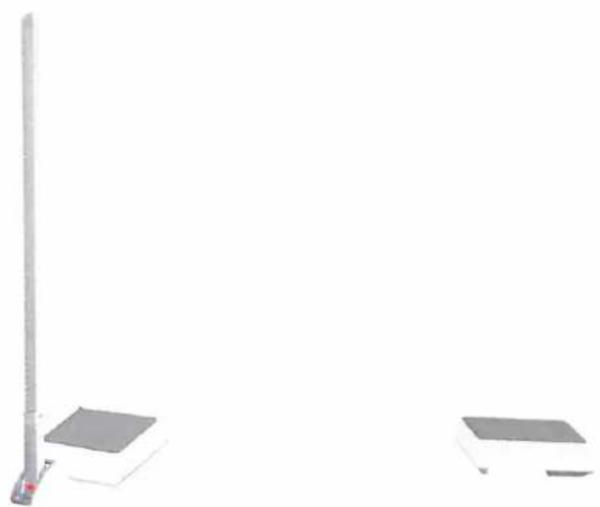
Simple gray square object with two small dark curved shapes at the bottom (no text or symbols)Figure 7 MPE personal scale with pole and height measure.

natural_image
White rectangular electronic device with a flat top and two small feet at the base (no visible text or symbols)Figure 8 MPE personal scale with pole.
text_image
KERN Max 250 kg Max 3 kg +0.1 kgFigure 9 Front layout of indicator on MPD
natural_image
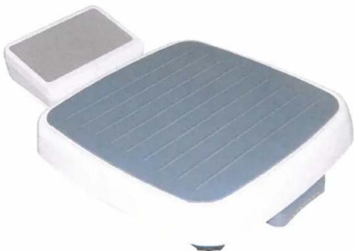
Exterior view of a modern office building (no signage)Figure 10 MPD personal scale.
text_image
self destroy label seal plate (ABS) calibration switch self destroy labelFigure 13 Sealing of indicator for model MPE.
text_image
self destory label self destroy label seal plate (ABS) calibration switchFigure 14 Sealing of indicator for model MBC / MPD / MPC / MCC.