
DCLE34033 - Laser level DEWALT - Free user manual and instructions
Find the device manual for free DCLE34033 DEWALT in PDF.

| Product type | 360° three-beam line laser level |
| Brand and model | DEWALT DCLE34033 |
| Laser class | Class 2 (IEC 60825-1:2014) |
| Laser wavelength | 510–530 nm (visible) |
| Laser power per beam | ≤ 1.50 mW |
| Range (without detector) | 70 m (230 ft) |
| Range (with detector) | 100 m (330 ft) |
| Accuracy (level and plumb) | ± 3 mm per 15.25 m (± 1/8 in per 50 ft) |
| Self-leveling range | ± 4° |
| Power supply | DEWALT 12 V MAX* or 20 V MAX* lithium-ion battery pack |
| Battery level indicator | 4 LED indicators (last one blinks at 10%) |
| Operating temperature | 4 °C to 40 °C (39.2 °F to 104 °F) |
| Storage temperature | -20 °C to 60 °C (-5 °F to 140 °F) |
| Protection rating | IP54 (tool only) |
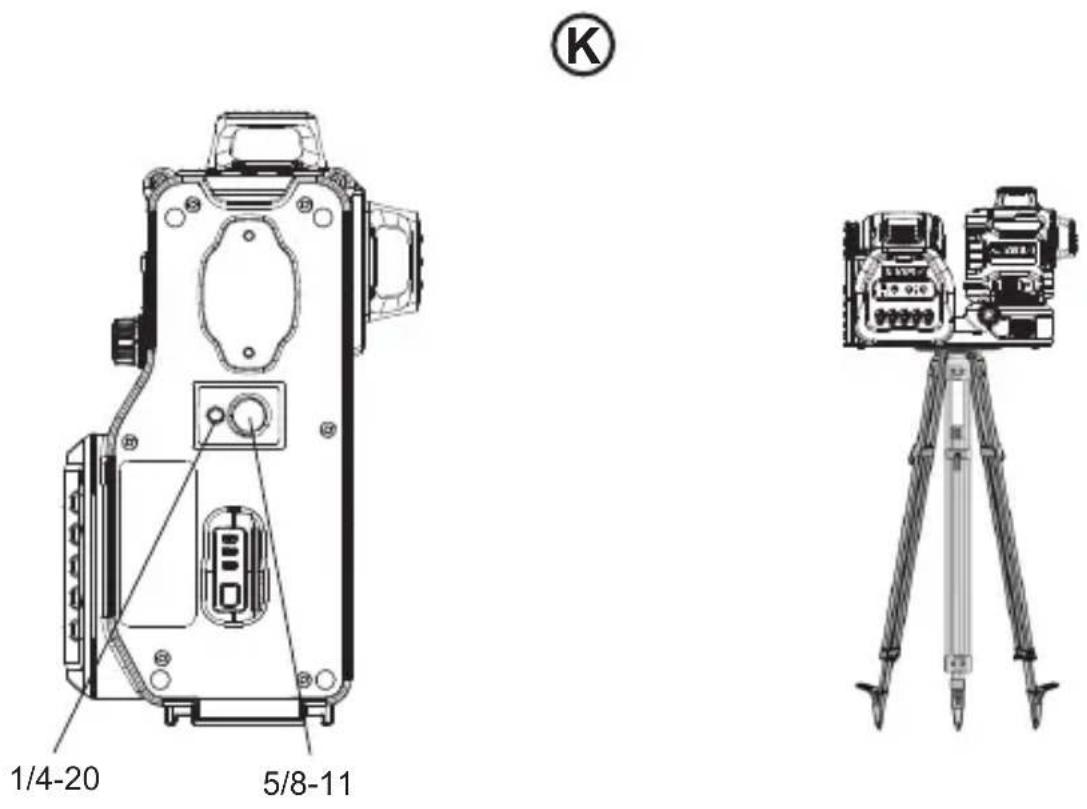
| Mounting | Integrated magnetic pivoting bracket, 1/4 in-20 and 5/8 in-11 threads |
| Main functions | 360° horizontal and vertical lines (front and side), self-leveling, pivoting bracket with fine adjustment |
| Maintenance and cleaning | Clean with a damp cloth, do not use solvents. Store in the provided case. |
| Safety | Turn off the laser when not in use, use the transport lock. Do not stare into the beam. |
| Spare parts and repairability | Repairs by authorized DEWALT service center only. |
| Included accessories | Carrying case, laser target card, ceiling mount bracket (version dependent) |
Frequently Asked Questions - DCLE34033 DEWALT
User questions about DCLE34033 DEWALT
0 question about this device. Answer the ones you know or ask your own.
Ask a new question about this device
Download the instructions for your Laser level in PDF format for free! Find your manual DCLE34033 - DEWALT and take your electronic device back in hand. On this page are published all the documents necessary for the use of your device. DCLE34033 by DEWALT.
USER MANUAL DCLE34033 DEWALT
natural_image
Technical line drawing of two DEWALT air conditioners with control panel and buttons (no text or symbols beyond branding)www.DeWALT.com

Please read these instructions before operating the product.
B

Figures
D
E

Figures
F

①
2
③
Figures
H
I
natural_image
Technical line drawing of a device with labeled components, no readable text or symbols presentJ
L
Figures


WARNING: Read all safety warnings and all instructions. Failure to follow the warnings and instructions may result in electric shock, fire and/or serious injury.

WARNING: To reduce the risk of injury, read the instruction manual.
Contents
- Laser Information
- User Safety
- Battery and Charger Safety
- Operating Tips
- Turning the Laser ON
- Checking Laser Accuracy
- Using the Laser
- Troubleshooting
- Accessories
• Service and Repairs - Warranty
- Specifications
Laser Information
The DCLE34033 3-Beam 360° Line Laser is a Class 2 laser product. It is a self-leveling laser tool that can be used for horizontal (level) and vertical (plumb) alignment projects.
This product complies with 21 CFR 1040.10 and 1040.11 except for conformance with IEC 60825-1 Ed.3., as described in Laser Notice No. 56, dated May 8, 2019.
Conforms to UL STDS 61010-1 & 2595
Certified to CSA STD C22.2 No. 61010-1
Supplier's Declaration of Conformity 47 CFR § 2.1077 Compliance Information
Responsible Party – U.S. Contact Information DEWALT
701 East Joppa Road
Towson, Maryland 21286
www.DEWALT.com
FCC Compliance Statement
This equipment has been tested and found to comply with the limits for a Class B digital device, pursuant to Part 15 of the FCC Rules. These limits are designed to provide reasonable protection against harmful interference in a residential installation. This equipment generates, uses and can radiate radio frequency energy and, if not installed and used in accordance with the instructions, may cause harmful interference to radio communications. However, there is no guarantee that interference will not occur in a particular installation. If this equipment does cause harmful interference to radio and television reception, which can be determined by turning the equipment off and on, the user is encouraged to try to correct the interference by one or more of the following measures:
- Reorient or relocate the receiving antenna.
- Increase the separation between the equipment and receiver.
- Connect the equipment into an outlet on a circuit different from that to which the receiver is connected.
- Consult the dealer or an experienced radio/TV technician for help.
ISED Compliance Statement
This device contains license-exempt transmitter(s)/receiver(s) that comply with Innovation, Science, and Economic Development Canada's license-exempt RSS(s). Operation is subject to the following two conditions:
- This device may not cause interference.
- This device must accept any interference, including interference that may cause undesired operation of the device.
E
User Safety
Safety Guidelines
The definitions below describe the level of severity for each signal word. Please read the manual and pay attention to these symbols.

DANGER: Indicates an imminently hazardous situation which, if not avoided, will result in death or serious injury.

WARNING: Indicates a potentially hazardous situation which, if not avoided, could result in death or serious injury.

CAUTION: Indicates a potentially hazardous situation which, if not avoided, may result in minor or moderate injury.
NOTICE: Indicates a practice not related to personal injury which, if not avoided, may result in property damage.
If you have any questions or comments about this or any DEWALT tool, call 1-800-4-DEWALT (1-800-433-9258) or go to www.DEWALT.com.

WARNING:
Never modify the tool or any part of it. Damage to the laser or personal injury could result.

WARNING:
Read and understand all instructions.
Failure to follow the warnings and instructions may result in electric shock, fire and/or serious injury.
SAVE THESE INSTRUCTIONS

WARNING:
Laser Radiation Exposure. Do not disassemble or modify the laser level. There are no user serviceable parts inside. Serious eye injury could result.

WARNING:
Hazardous Radiation. Use of controls or adjustments or performance of procedures other than those specified herein may result in hazardous radiation exposure.

CAUTION: Keep fingers clear of the back plate and stud when mounting with magnets. Fingers may become pinched.

CAUTION: Do not stand underneath the laser when it is mounted with the magnet bracket. Serious personal injury or damage to the laser may result if the laser falls.
The label on your laser may include the following symbols.
| Symbol Meaning | |
| V Volts | |
| mW Milliwatts | |
| Laser Warning | |
| nm Wavelength in nanometers | |
| 2 Class 2 Laser | |
Warning Labels
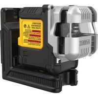
For your convenience and safety, the following labels are on your laser (Figure ⑧).
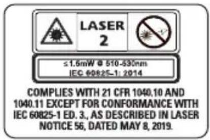
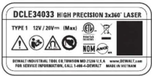


WARNING: To reduce the risk of injury, user must read instruction manual.

WARNING: LASER RADIATION. DO NOT STARE INTO BEAM. Class 2 Laser Product.


Keep clear of magnet. Magnet hazard can disturb pacemaker operation and result in serious injury or death.
- If the equipment is used in a manner not specified by the manufacturer, the protection provided by the equipment may be impaired.
- Do not operate the laser in explosive atmospheres, such as in the presence of flammable liquids, gases, or dust. This tool may create sparks which may ignite the dust or fumes.
- Store an idle laser out of reach of children and other untrained persons. Lasers are dangerous in the hands of untrained users.
- Tool service MUST be performed by qualified repair personnel. Service or maintenance performed by unqualified personnel may result in injury. To locate your nearest DEWALT service center go to www.DEWALT.com.
- Do not use optical tools such as a telescope or transit to view the laser beam. Serious eye injury could result.
-
Do not place the laser in a position which may cause anyone to intentionally or unintentionally stare into the laser beam. Serious eye injury could result.
-
Do not position the laser near a reflective surface which may reflect the laser beam toward anyone's eyes. Serious eye injury could result.
- Turn the laser off when it is not in use. Leaving the laser on increases the risk of staring into the laser beam.
- Do not modify the laser in any way. Modifying the tool may result in hazardous laser radiation exposure.
- Do not operate the laser around children or allow children to operate the laser. Serious eye injury may result.
- Do not remove or deface warning labels. If labels are removed, the user or others may inadvertently expose themselves to radiation.
- Position the laser securely on a level surface. If the laser falls, damage to the laser or serious injury could result.
Personal Safety
- Stay alert, watch what you are doing, and use common sense when operating the laser. Do not use the laser when you are tired or under the influence of drugs, alcohol, or medication. A moment of inattention while operating the laser may result in serious personal injury.
- Use personal protective equipment. Always wear eye protection. Depending on the work conditions, wearing protective equipment such as a dust mask, non-skid safety shoes, hard hat, and hearing protection will reduce personal injury.
Tool Use and Care
- Do not use the laser if the Power/Transport Lock switch does not turn the laser on or off. Any tool that cannot be controlled with the switch is dangerous and must be repaired.
- Follow instructions in the Maintenance section of this manual. Use of unauthorized parts or failure to
E
follow Maintenance instructions may create a risk of electric shock or injury.
Battery and Charger Safety

WARNING: Batteries can explode, or leak, and can cause injury or fire. To reduce this risk:
The battery pack is not fully charged out of the carton. Before using the battery pack and charger, read the safety instructions below and then follow charging procedures outlined. When ordering replacement battery packs, be sure to include the catalog number and voltage.
READ ALL INSTRUCTIONS
Important Safety Instructions for All Battery Packs

WARNING: Read all safety warnings, instructions, and cautionary markings for the battery pack, charger and product. Failure to follow the warnings and instructions may result in electric shock, fire and/or serious injury.
- Do not charge or use the battery pack in explosive atmospheres, such as in the presence of flammable liquids, gases or dust. Inserting or removing the battery pack from the charger may ignite the dust or fumes.
- NEVER force the battery pack into the charger. DO NOT modify the battery pack in any way to fit into a non-compatible charger as battery pack may rupture causing serious personal injury. Consult the chart at the end of this manual for compatibility of batteries and chargers.
- Charge the battery packs only in DEWALT chargers.
- DO NOT splash or immerse in water or other liquids.
-
DO NOT allow water or any liquid to enter battery pack.
-
Do not store or use the tool and battery pack in locations where the temperature may reach or exceed 104 °F (40 °C) (such as outside sheds or metal buildings in summer). For best life store battery packs in a cool, dry location. NOTE: Do not store the battery packs in a tool with the trigger switch locked on. Never tape the trigger switch in the ON position.
- Do not incinerate the battery pack even if it is severely damaged or is completely worn out. The battery pack can explode in a fire. Toxic fumes and materials are created when lithium-ion battery packs are burned.
- Do not expose a battery pack or appliance to fire or excessive temperature. Exposure to fire or temperature above 265 °F (130 °C) may cause explosion.
- If battery contents come into contact with the skin, immediately wash area with mild soap and water. If battery liquid gets into the eye, rinse water over the open eye for 15 minutes or until irritation ceases. If medical attention is needed, the battery electrolyte is composed of a mixture of liquid organic carbonates and lithium salts.
- Contents of opened battery cells may cause respiratory irritation. Provide fresh air. If symptoms persist, seek medical attention.
- Battery liquid may be flammable if exposed to spark or flame.
- Never attempt to open the battery pack for any reason. If the battery pack case is cracked or damaged, do not insert into the charger. Do not crush, drop or damage the battery pack. Do not use a battery pack or charger that has received a sharp blow, been dropped, run over or damaged in any way (e.g., pierced with a nail, hit with a hammer, stepped on). Damaged battery packs should be returned to the service center for recycling.
Storage Recommendations
The best storage place is one that is cool and dry, away from direct sunlight and excess heat or cold. Store the fully charged battery pack out of the charger.
Battery Pack Cleaning Instructions
Dirt and grease may be removed from the exterior of the battery pack using a cloth or soft non-metallic brush. Do not use water or any cleaning solutions.
Fuel Gauge Battery Packs (Fig. C)
Some battery packs include a fuel gauge. When the fuel gauge button is pressed and held, the LED lights will indicate the approximate level of charge remaining. This does not indicate tool functionality and is subject to variation based on product components, temperature, and end-user application.
Transportation

WARNING: Fire hazard. Do not store, carry, or transport the battery pack so that metal objects can contact exposed battery terminals. For example, do not place the battery pack in aprons, pockets, tool boxes, product kit boxes, drawers, etc., with loose nails, screws, keys, coins, hand tools, etc. When transporting individual battery packs, make sure that the battery terminals are protected and well insulated from materials that could contact them and cause a short circuit. NOTE: Li-ion battery packs should not be put in checked baggage on airplanes and must be properly protected from short circuits if they are in carry-on baggage.
The RBRC® Seal
Please take your spent battery packs to an authorized DEWALT service center or to your local retailer for recycling. In some areas, it is illegal

to place spent battery packs in the trash. You may also contact your local recycling center for information on where to drop off the spent battery pack. Do not place in curbside recycling. For more information visit www.call2recycle.org. or call the toll free number in the RBRC® Seal.
RBRC® is a registered trademark of Call 2 Recycle, Inc.
Powering the Laser
This laser can be powered by either of these battery packs:
• A DEWALT 12V MAX* Li-ion Battery Pack.
*Maximum initial battery voltage (measured without a workload) is 12 volts. Nominal voltage is 10.8.
• A DEWALT 20V MAX* Li-ion Battery Pack.
*Maximum initial battery voltage (measured without a workload) is 20 volts. Nominal voltage is 18.
| Battery Type | Battery Pack |
| 12V | DCB120, DCB121, DCB122, DCB123, DCB124, DCB125, DCB126, DCB127 |
| 20V | DCB201, DCB203, DCB203BT, DCB204, DCB204BT, DCB205, DCB205BT, DCB206, DCB207, DCB208, DCB230, DCB240, DCBP520, DCBP034 |
Use only DEWALT battery packs and chargers. Use of any other batteries may create a risk of fire.
Important Safety Instructions for All Battery Chargers

WARNING: Read all safety warnings, instructions, and cautionary markings for the battery pack, charger and product. Failure to follow the warnings and instructions may result in electric shock, fire and/or serious injury.
E
- DO NOT attempt to charge the battery pack with any chargers other than a DEWALT charger. DEWALT chargers and battery packs are specifically designed to work together.
- These chargers are not intended for any uses other than charging DEWALT rechargeable battery packs. Charging other types of battery packs may cause them to overheat and burst, resulting in personal injury, property damage, fire, electric shock or electrocution.
- Do not expose the charger to rain or snow.
- Do not allow water or any liquid to enter charger.
- Pull by the plug rather than the cord when disconnecting the charger. This will reduce the risk of damage to the electric plug and cord.
- Make sure that the cord is located so that it will not be stepped on, tripped over or otherwise subjected to damage or stress.
- Do not use an extension cord unless it is absolutely necessary. Use of improper extension cord could result in risk of fire, electric shock or electrocution.
- When operating a charger outdoors, always provide a dry location and use an extension cord suitable for outdoor use. Use of a cord suitable for outdoor use reduces the risk of electric shock.
- An extension cord must have adequate wire size (AWG or American Wire Gauge) for safety. The smaller the gauge number of the wire, the heavier the cord and thus the greater its capacity. An undersized cord will cause a drop in line voltage resulting in loss of power and overheating. The following table shows the correct size to use depending on total length of all extension cords plugged together, and nameplate ampere rating. If in doubt, use the next heavier gauge.
Minimum Gauge for Cord Sets
| Volts | Total Length of Cord in Feet (meters) | ||||
| 120V 25 (7.6) | 50(15.2) | 100(30.5) | 150(45.7) | ||
| Ampere Rating | American Wire Gauge | ||||
| More Than Not More | |||||
| Than | |||||
| 0 6 18 16 16 14 | |||||
| 6 10 18 16 14 12 | |||||
| 10 12 16 16 14 12 | |||||
| 12 16 14 12 Not | Recommended | ||||
- Do not place any object on top of the charger or place the charger on a soft surface that might block the ventilation slots and result in excessive internal heat. Place the charger in a position away from any heat source. The charger is ventilated through slots in the top and the bottom of the housing.
- Do not operate the charger with a damaged cord or plug. Have them replaced immediately.
- Do not operate the charger if it has received a sharp blow, been dropped or otherwise damaged in any way. Take it to an authorized service center.
- Do not disassemble the charger; take it to an authorized service center when service or repair is required. Incorrect reassembly may result in a risk of electric shock, electrocution or fire.
- The charger is designed to operate on standard 120V household electrical power. Do not attempt to use it on any other voltage. This does not apply to the vehicular charger.
- Foreign materials of a conductive nature, such as, but not limited to, grinding dust, metal chips, steel wool, aluminum foil or any buildup of metallic particles should be kept away from the charger cavities and ventilation slots.
- Always unplug the charger from the power supply when there is no battery pack in the cavity.
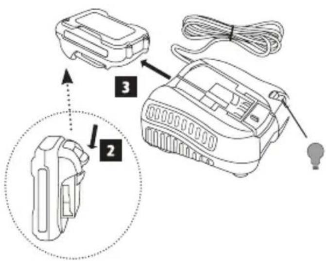
Charging a Battery (Fig. A–C)
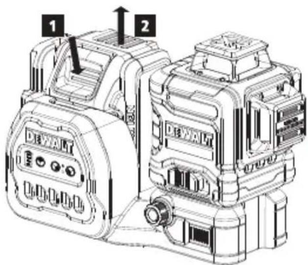
- If the DEWALT 12V/20V MAX* Li-ion battery pack is attached to the laser, remove it.
- While pressing down on the release button on the battery pack (Figure ⑧①), pull the battery pack up to unlock it from the laser.
- Pull the battery pack the rest of the way up and out of the laser (Figure B 2).
- Plug the charger into an appropriate outlet.
- Insert and fully seat battery pack (Fig. A 1). The red charging light(s) will continuously blink while charging.
- Charging is complete when the red charging light(s) remain(s) continuously ON. Battery pack can be left in charger or removed (Fig. A 3). Some chargers require the battery pack release button to be pressed for removal (Fig. A 2).
WARNING: Only charge batteries in air temperature over 40 °F ( 4.5 °C ) and below 104 °F (+ 40 °C ). - Charger will not charge a faulty battery pack, which may be indicated by the charging light(s) staying OFF. Take charger and battery pack to an authorized service center if light(s) stay(s) OFF.
NOTE: Refer to label near charging light(s) on charger for blink patterns. Older chargers may have additional information and/or may not have a yellow indicator light.
NOTE: To remove the battery pack, some chargers require the battery pack release button to be pressed. - Slide the battery pack down in the laser until it snaps in place (Figure A 4).

Viewing the Battery Meter
When the laser is ON, the battery meter on the keypad (Figure ⑦) indicates how much power remains.
- The bottom LED will illuminate and flash when the battery level is low (10%). The laser may continue to operate for a short time while the battery power continues to drain, but the beam(s) will quickly dim.
- After the 12V/20V MAX Li-ion battery is charged, and the laser is turned ON again, the laser beam(s) will return to full brightness and the battery indicator level will indicate full capacity.
- If all 4 LEDs on the battery meter remain ON, this indicates that the laser is not fully powered OFF. When the laser is not in use, make sure the Power/Transport Lock switch is placed to the LEFT to the Locked/OFF position (Figure C ②).
Hot/Cold Pack Delay
When the charger detects a battery pack that is too hot or too cold, it automatically starts a Hot/Cold Pack Delay, suspending charging until the battery pack has reached an appropriate temperature. The charger then automatically switches to the pack charging mode. This feature ensures maximum battery pack life.
A cold battery pack may charge at a slower rate than a warm battery pack.
The hot/cold pack delay will be indicated by the red light(s) continuing to blink but with the yellow light continuously ON. Once the battery pack has reached an appropriate temperature, the yellow light will turn OFF and the charger will resume the charging procedure.
DCB118 and DCB1112 Chargers
The DCB118 and DCB1112 chargers are equipped with an internal fan designed to cool the battery pack. The fan will turn on automatically when the battery pack needs to be cooled.
Never operate the charger if the fan does not operate properly or if ventilation slots are blocked. Do not permit foreign objects to enter the interior of the charger.
Electronic Protection System
Li-Ion tools are designed with an Electronic Protection System that will protect the battery pack against
E
overloading, overheating or deep discharge. The tool will automatically turn off and the battery pack will need to be recharged.
Important Charging Notes
- Longest life and best performance can be obtained if the battery pack is charged when the air temperature is between 65 °F – 75 °F (18 °C–24 °C). DO NOT charge when the battery pack is below +40 °F (+4.5 °C), or above +104 °F (+40 °C). This is important and will prevent serious damage to the battery pack.
- The charger and battery pack may become warm to the touch while charging. This is a normal condition, and does not indicate a problem. To facilitate the cooling of the battery pack after use, avoid placing the charger or battery pack in a warm environment such as in a metal shed or an uninsulated trailer.
- If the battery pack does not charge properly:
a. Check operation of receptacle by plugging in a lamp or other appliance;
b. Check to see if receptacle is connected to a light switch which turns power off when you turn out the lights;
c. If charging problems persist, take the tool, battery pack and charger to your local service center.
- You may charge a partially used pack whenever you desire with no adverse effect on the battery pack.
Charger Cleaning Instructions

WARNING: Shock hazard. Disconnect the charger from the AC outlet before cleaning. Dirt and grease may be removed from the exterior of the charger using a cloth or soft non-metallic brush. Do not use water or any cleaning solutions.
Operating Tips
- To extend battery life per charge, turn the laser off when it is not in use.
- To ensure the accuracy of your work, check the laser calibration often. Refer to Checking Laser Accuracy.
- Before attempting to use the laser, make sure it is positioned securely, on a smooth, flat stable surface that is level in both directions.
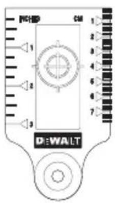
- To increase beam visibility, use a Laser Target Card (Figure M) to help find the beam.
- Always mark the center of the beam created by the laser.
- Extreme temperature changes can cause movement or shifting of building structures, metal tripods, equipment, etc., which can effect accuracy. Check your accuracy often while working.
- If the laser has been dropped, check to make sure your laser is still calibrated. Refer to Checking Laser Accuracy.
Turning the Laser On
Place the laser on a flat level surface. Slide the Power/Transport Lock switch Ⓒ② to the right to unlock/turn ON the laser.
Each laser line is powered on by pressing its button on the keypad (Figure ③). Pressing the button again turns the laser line off. The laser lines can be powered one at a time or all at the same time.
| Button Displays | |
 | Horizontal laser line (Figure 4) |
 | Side vertical laser line (Figure 5) |
 | Front vertical laser line (Figure 6) |
When the laser is not in use, slide the Power/Transport Lock switch to the left in the OFF/Locked position. If the Power/Transport Lock switch is not placed in the lock position, all 4 LEDs will continuously flash on the Battery Meter.
Checking Laser Accuracy
The laser tools are sealed and calibrated at the factory. It is recommended that you perform an accuracy check prior to using the laser for the first time (in case the laser was exposed to extreme temperatures) and then regularly to ensure the accuracy of your work. When performing any of the accuracy checks listed in this manual, follow these guidelines:
- Use the largest area/distance possible, closest to the operating distance. The greater the area/distance, the easier to measure the accuracy of the laser.
- Place the laser on a smooth, flat, stable surface that is level in both directions.
• Mark the center of the laser beam.
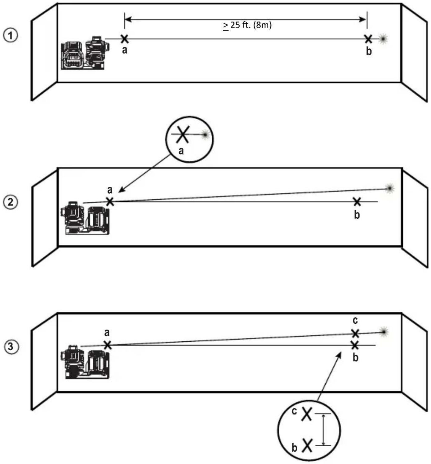
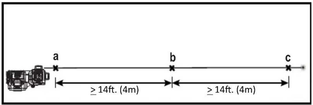
Horizontal Beam - Scan Direction
Checking the horizontal scan calibration of the laser requires two walls 30' (9m) apart. It is important to conduct a calibration check using a distance no shorter than the distance of the applications for which the tool will be used.
- Place the laser against the end of the wall on a smooth, flat, stable surface that is level in both directions (Figure ①).
- Move the Power/Transport Lock switch to the right to turn the laser ON.
- Press turn on the horizontal beam.
- At least 30' (9m) apart along the laser beam, mark a and b.
- Turn the laser 180°.
-
Adjust the height of the laser so the center of the beam is aligned with ⓐ (Figure D ②).
-
Directly above or below ⓑ, mark Ⓒ along the laser beam (Figure D ③).
- Measure the vertical distance between ⓑ and Ⓒ.
- If your measurement is greater than the Allowable Distance Between ⓑ and Ⓒ for the corresponding Distance Between Walls in the following table, the laser must be serviced at an authorized service center.
| Distance Between Walls | Allowable Distance Between ⓑ and Ⓒ |
| 25' 1/8" | |
| 35' 3/16" | |
| 50' 1/4" | |
| 75' 3/8" | |
| 100' 1/2" |
| Distance Between Walls | Allowable Distance Between ⓑ and Ⓒ |
| 10.0 m 4 mm | |
| 15.0 m 6 mm | |
| 20.0 m 8 mm | |
| 23.0 m 10 mm | |
| 30.0 m 12 mm |
Horizontal Beam - Pitch Direction
Checking the horizontal pitch calibration of the laser requires a single wall at least 30' (9m) long. It is important to conduct a calibration check using a distance no shorter than the distance of the applications for which the tool will be used.
- Place the laser against the end of the wall on a smooth, flat, stable surface that is level in both directions (Figure ①).
- Move the Power/Transport Lock switch to the right to turn the laser ON.
- Press to turn on the horizontal beam.
E
- At least 30' (9m) apart along the laser beam, mark a and b.
- Move the laser to the opposite end of the wall (Figure ⑤ ②).
- Position the laser toward the first end of the same wall and parallel to the adjacent wall.
- Adjust the height of the laser so the center of the beam is aligned with ⓑ.
- Directly above or below a, mark c along the laser beam (Figure E 3).
- Measure the distance between and .
- If your measurement is greater than the Allowable Distance Between a and c for the corresponding Distance Between Walls in the following table, the laser must be serviced at an authorized service center.
| Distance Between Walls | Allowable Distance Between a and c |
| 25' 1/8" | |
| 35' 3/16" | |
| 50' 1/4" | |
| 75' 3/8" | |
| 100' 1/2" |
| Distance Between Walls | Allowable Distance Between a and c |
| 10.0 m 4 mm | |
| 15.0 m 6 mm | |
| 20.0 m 8 mm | |
| 23.0 m 10 mm | |
| 30.0 m 12 mm |
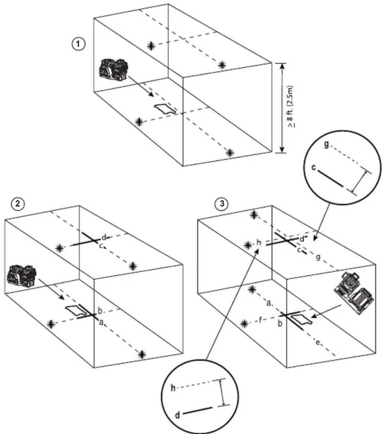
Vertical Beam
Checking the vertical (plumb) calibration of the laser can be most accurately done when there is a substantial amount of vertical height available, ideally 30' (9m), with one person on the floor positioning
the laser and another person near a ceiling to mark the position of the beam. It is important to conduct a calibration check using a distance no shorter than the distance of the applications for which the tool will be used.
- Place the laser on a smooth, flat, stable surface that is level in both directions (Figure F ①).
- Move the Power/Transport Lock switch to the right to turn the laser ON.
- Press and to turn on both vertical beams.
- Mark two short lines where the beams cross a, b and also on the ceiling c, d. Always mark the center of the beam's thickness (Figure F 2).
- Pick up and rotate the laser 180^ , and position it so the beams line up with the marked lines on the level surface (e, f) (Figure F 3).
- Mark two short lines where the beams cross on the ceiling ⑨, ⑧.
- Measure the distance between each set of marked lines on the ceiling (c, g and d, h). If the measurement is greater than the values shown below, the laser must be serviced at an authorized service center.
| Ceiling Height | Allowable Distance Between Marks |
| 8' 3/64" | |
| 12' 1/16" | |
| 14' 5/64" | |
| 18' 3/32" | |
| 30' 5/32" |
| Ceiling Height | Allowable Distance Between Marks |
| 2.5 m 1.0 mm | |
| 3.5 m 1.5 mm | |
| 4.0 m 2.0 mm | |
| 6.0 m 2.5 mm | |
| 9.0 m 4.0 mm |
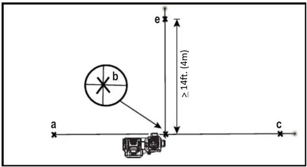
90° Accuracy Between Vertical Beams
Checking 90° accuracy requires an open floor area at least 33' x 18' (10m x 5m). Refer to Figure G for the position of the laser at each step and for the location of the marks made at each step. Always mark the center of the beam's thickness.
- Place the laser on a smooth, flat, stable surface that is level in both directions.
- Move the Power/Transport Lock switch to the right to turn the laser ON.
- Press ⑩ turn on the side vertical beam.
- Mark the center of the beam at three locations (a, b, c) on the floor along the side laser line. Mark (b) should be at the midpoint of the laser line (Figure G 1).
- Pick up and move the laser to ⓑ.
- Press to turn on the front vertical beam too (Figure G 2).
- Position the front vertical beam so it crosses precisely at ⓑ, with the side beam aligned with ⓒ (Figure Ⓖ 2).
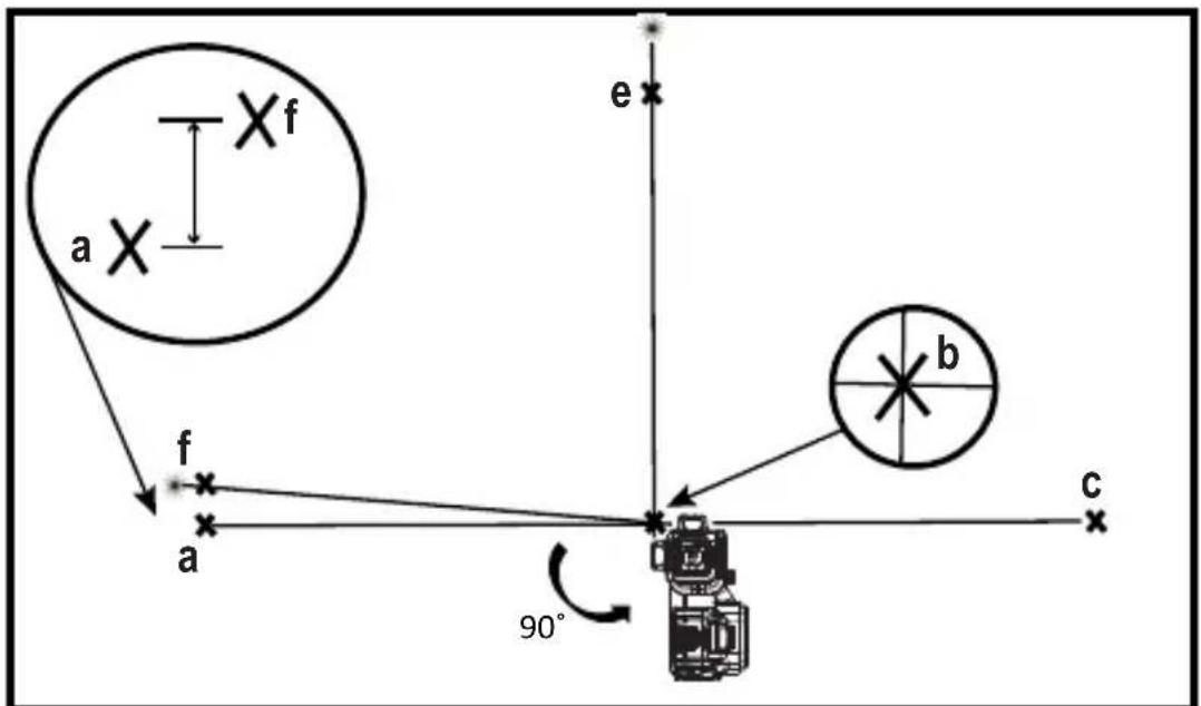
- Mark a location ⓔ along the front vertical beam at least 14' (4m) away from the unit (Figure G 2).
- Rotate the laser 90^ so the side vertical beam now passes through ⓑ and ⓔ (Figure Ⓖ 3).
- Directly above or below ⓐ, mark ⓕ along the front vertical beam.
- Measure the distance between and . If the measurement is greater than the values shown below, the laser must be serviced at an authorized service center.
| Distance froma to b | Allowable DistanceBetween a and f |
| 14' 5/32" | |
| 17' 3/16" | |
| 20' 7/32" |
| Distance froma to b | Allowable DistanceBetween a and f |
| 23' 1/4" |
| Distance froma to b | Allowable DistanceBetween a and f |
| 4.0 m 3.5 mm | |
| 5.0 m 4.4 mm | |
| 6.0 m 5.3 mm | |
| 7.0 m 6.2 mm |
Using the Laser
Leveling the Laser
As long as the laser is properly calibrated, the laser is self-leveling. Each laser is calibrated at the factory to find level as long as it is positioned on a flat surface within average ±4^ of level. No manual adjustments are required.
If the laser has been tilted so much that it cannot self-level ( >4^ ), the laser beam will flash. There are two flashing sequences associated with the out of level condition.
- Between 4^ and 10^ the beams flash with a constant blink cycle.
- At angles greater than 10^ the beams flash with a three blink cycle.
When the beams flash THE LASER IS NOT LEVEL (OR PLUMB) AND SHOULD NOT BE USED FOR DETERMINING OR MARKING LEVEL OR PLUMB. Try repositioning the laser on a more level surface.
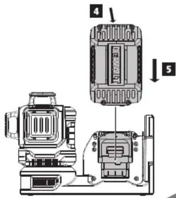
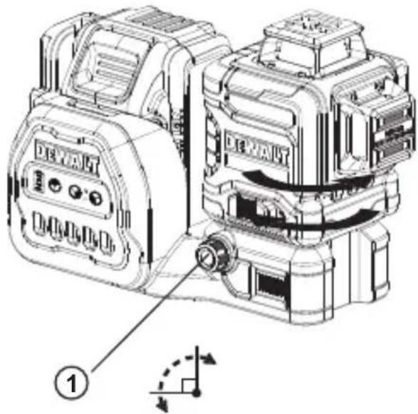
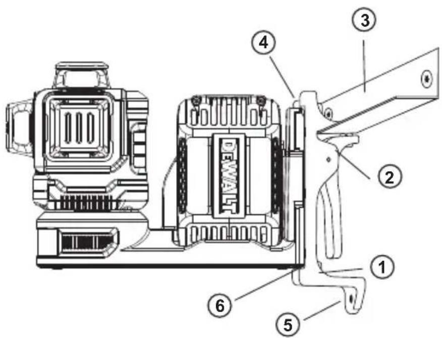
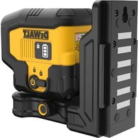
Using the Pivot Bracket
The laser has a magnetic pivot bracket (Figure ①) permanently attached to the unit.

WARNING:
Position the laser and/or wall mount on a stable surface. Serious personal injury or
E
damage to the laser may result if the laser falls.
- The bracket has a fine adjustment knob (Figure ①) to help you line up the laser beams. Place the unit on a flat level surface and turn the knob to the right to move the beams to the right, or turn the knob to the left to move the beams to the left.
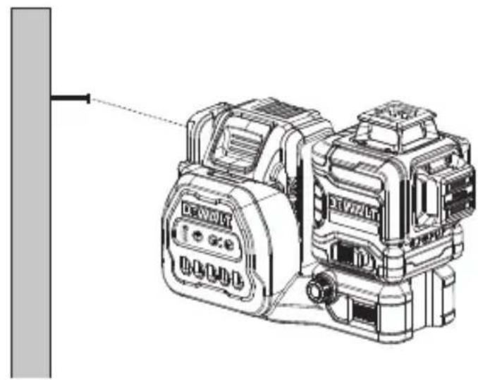
- The bracket has a keyhole slot (Figure ①) so it can be hung from a nail or screw on any kind of surface.
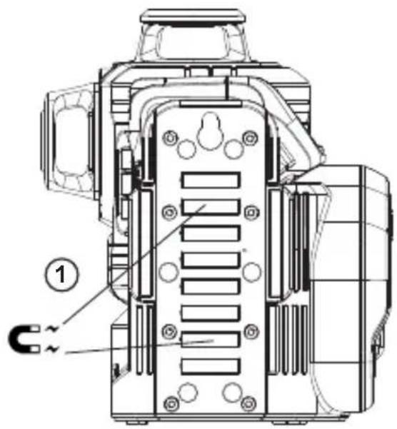
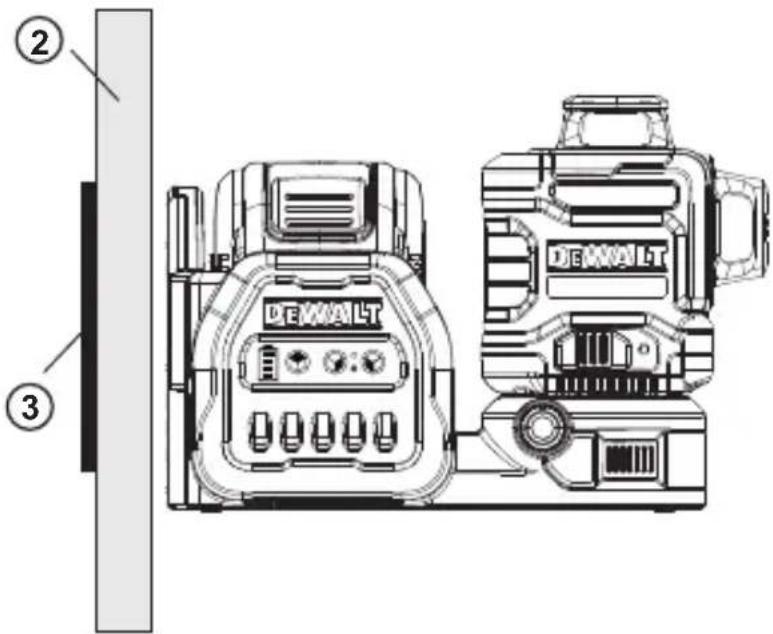
- The bracket has magnets (Figure ①) which allow the unit to be mounted to most upright surfaces made of steel or iron. Common examples of suitable surfaces include steel framing studs, steel door frames, and structural steel beams. Before attaching the pivot bracket against a stud (Figure ②), place the Metal Enhancement Plate (Figure ③) on the opposite side of the stud.
Maintenance
- To maintain the accuracy of your work, check the laser often to make sure it is properly calibrated. See Field Calibration Check.
- Calibration checks and other maintenance repairs may be performed by DEWALT service centers.
- When not in use, store the laser in the kit box provided. Do not store your laser at temperatures below -5^ (-20°C) or above 140^ (60°C).
- Do not store your laser in the kit box if the laser is wet. The laser should be dried first with a soft dry cloth prior to storage.
Cleaning
Exterior plastic parts may be cleaned with a damp cloth. Although these parts are solvent resistant, NEVER use solvents. Use a soft, dry cloth to remove moisture from the tool before storage.
Troubleshooting
The Laser Does Not Turn On
- Fully-charge the battery pack and then reinstall it in the laser unit.
- If the laser unit is heated above 120^ F ( 50^ C), the unit will not turn on. If the laser has been stored in extremely hot temperatures, allow it to cool. The laser level will not be damaged by pressing the on/off button before cooling to its proper operating temperature.
The Laser Beams Flash
The lasers are designed to self-level up to an average of 4^ in all directions. If the laser is tilted so much that the internal mechanism cannot level itself, the laser beams will flash indicating that the tilt range has been exceeded. THE FLASHING BEAMS CREATED BY THE LASER ARE NOT LEVEL OR PLUMB AND SHOULD NOT BE USED FOR DETERMINING OR MARKING LEVEL OR PLUMB. Try repositioning the laser on a more level surface.
The Laser Beams Will Not Stop Moving
The laser is a precision instrument. Therefore, if it is not positioned on a stable (and motionless) surface, the laser will continue to try to find level. If the beam will not stop moving, try placing the laser on a more stable surface. Also, try to make sure that the surface is relatively flat, so that the laser is stable.
The Battery Meter LEDs Flash
When all 4 LEDs continuously flash on the Battery Meter this indicates that the unit has not been fully powered off using the Power/Transport Lock switch (Figure C②). The Power/Transport Lock switch should always be placed in the LOCKED/OFF position when the laser is not in use.
Accessories
The laser is equipped with both 1/4 - 20 and 5/8 - 11 female threads on the bottom of the unit (Figure K). This thread is to accommodate current or future DeWALTaccessories. Only use DeWALT accessories specified for use with this product. Follow the directions included with the accessory.

WARNING:
Since accessories, other than those offered by DEWALT, have not been tested with this product, use of such accessories with this tool could be hazardous. To reduce the risk of injury, only DEWALT recommended accessories should be used with this product.
If you need any assistance in locating any accessory, please contact your nearest DEWALT service center or go to www.DEWALT.com.
Target Card
Some laser kits include a Laser Target Card (Figure M) to aid in locating and marking the laser beam. The target card enhances the visibility of the laser beam as the beam crosses over the card. The card is marked with standard and metric scales. The laser beam passes through the green plastic and reflects off of the reflective tape on the reverse side. The magnet at the top of the card is designed to hold the target card to ceiling track or steel studs to determine plumb and level positions. For best performance when using the Target Card, the DEWALT logo should be facing you.
Ceiling Mount
The laser ceiling mount (Figure ①) offers more mounting options for the laser. The ceiling mount has a clamp (Figure ②) at one end which can be fixed to a wall angle for acoustic ceiling installation (Figure ③). At each end of the ceiling mount is a screw hole (Figure ④ and ⑤), allowing the ceiling mount to be attached to any surface with a nail or screw.
Once the ceiling mount is secured, its steel plate provides a surface to which the magnetic pivot bracket (Figure ⑤⑥) can be attached. The position of the laser can then be fine-tuned by sliding the magnetic pivot bracket up or down on the wall mount.
Service and Repairs
NOTE: Disassembling the laser level(s) will void all warranties on the product.
To assure product SAFETY and RELIABILITY, repairs, maintenance and adjustment should be performed by authorized service centers. Service or maintenance performed by unqualified personnel may result in a risk of injury. To locate your nearest DeWALT service center call 1-800-4-DEWALT (1-800-433-9258) or go to www.toolservicenet.com.
Warranty
Go to www.DEWALT.com for the latest warranty information.
| DCLE34033 | |
| Light Source Laser diodes | |
| Laser Wavelength 510 – 530 nm visible | |
| Laser Power ≤1.50 mW (each beam) CLASS 2 LASER PRODUCT | |
| Working Range 230' (70 m) | 330' (100 m) with detector |
| Accuracy (Plumb) ±1/8" per 50' (±3 mm per 15.25 m) | |
| Accuracy (Level) ±1/8" per 50' (±3 mm per 15.25 m) | |
| Battery Low 1 LED Flashing on Battery meter | |
| Unit Not Powered Off With Pendulum Lock Switch | 4 LEDs Flashing on Battery meter |
| Flashing Laser Beams Tilt range exceeded/unit is not level | |
| Power Source DEWALT 12 V or 20 V Battery Pack | |
| Operating Temperature 39.2 °F to 104 °F (4 °C to 40 °C) | |
| Storage Temperature 39.2 °F to 104 °F (4 °C to 40 °C) | |
| Humidity Maximum relative humidity 80% for temperatures up to 88°F (31°C),decreasing linearly to 50% relative humidity at 104°F (40°C) | |
| Environmental Water & Dust | Resistant to IP54. Applies to product, not battery or charger. WARNING: This product (not including the battery pack or charger)has an IP rating which provides some level of protection from dust(limited ingress) and liquids (light splashing) during normal andreasonably foreseeable use. The battery pack and charger do nothave an IP rating on their own. NEVER submerge the product,battery or charger in liquid. WARNING: This product (not including the battery pack or charger)has an IP rating which provides some level of protection from dust(limited ingress) and liquids (light splashing) during normal andreasonably foreseeable use. The battery pack and charger do nothave an IP rating on their own. NEVER submerge the product,battery or charger in liquid. |
| Altitude < 6500' (2000 m) | |

Towson, Maryland 21286
www.DEWALT.com
Towson, Maryland 21286
www.DEWALT.com
| Type de Pile Blocs-piles | |
| 12V | DCB120, DCB121, DCB122, DCB123, DCB124, DCB125, DCB126, DCB127 |
| Type de Pile | Blocs-piles |
| 20V | DCB201, DCB203, DCB203BT, DCB204, DCB204BT, DCB205, DCB205BT, DCB206, DCB207, DCB208, DCB230, DCB240, DCBP520, DCBP034 |
Towson, Maryland 21286
www.DEWALT.com
| Tipo de Bateria | Bateria |
| 12 V | DCB120, DCB121, DCB122, DCB123, DCB124, DCB125, DCB126, DCB127 |
| 20 V | DCB201, DCB203, DCB203BT, DCB204, DCB204BT, DCB205, DCB205BT, DCB206, DCB207, DCB208, DCB230, DCB240, DCBP520, DCBP034 |
| Distância entre as Paredes | Distância Permitida entre b e c |
| 10,0 m 4 mm | |
| 15,0 m 6 mm | |
| 20,0 m 8 mm | |
| 23,0 m 10 mm | |
| 30,0 m 12 mm |
| Distância entre as Paredes | Distância Permitida entre b e c |
| 25' 1/8" | |
| 35' 3/16" | |
| 50' 1/4" | |
| 75' 3/8" | |
| 100' 1/2" |
| Distância entre as Paredes | Distância Permitida entre a e c |
| 10,0 m 4 mm | |
| 15,0 m 6 mm | |
| 20,0 m 8 mm | |
| 23,0 m 10 mm | |
| 30,0 m 12 mm |
| Distância entre as Paredes | Distância Permitida entre a e c |
| 25' 1/8" | |
| 35' 3/16" | |
| 50' 1/4" | |
| 75' 3/8" | |
| 100' 1/2" |
Feixe Vertical
| Altura do Teto | Distância Permitida entre as Marcas |
| 2,5 m 1,0 mm | |
| 3,5 m 1,5 mm | |
| 4,0 m 2,0 mm | |
| 6,0 m 2,5 mm | |
| 9,0 m 4,0 mm |
| Altura do Teto | Distância Permitida entre as Marcas |
| 8' 3/64" | |
| 12' 1/16" | |
| 14' 5/64" | |
| 18' 3/32" | |
| 30' 5/32" |
90° entre os Feixes Verticais
Towson, Maryland 21286
NA350627 July 2023

- www.DeWALT.com
- Contents
- Laser Information
- FCC Compliance Statement
- ISED Compliance Statement
- E
- User Safety
- Safety Guidelines
- WARNING:
- SAVE THESE INSTRUCTIONS
- Warning Labels
- Personal Safety
- Tool Use and Care
- Battery and Charger Safety
- READ ALL INSTRUCTIONS
- Important Safety Instructions for All Battery Packs
- Storage Recommendations
- Battery Pack Cleaning Instructions
- Fuel Gauge Battery Packs (Fig. C)
- Transportation
- The RBRC® Seal
- Powering the Laser
- Important Safety Instructions for All Battery Chargers
- Charging a Battery (Fig. A–C)
- Viewing the Battery Meter
- Hot/Cold Pack Delay
- DCB118 and DCB1112 Chargers
- Electronic Protection System
- Important Charging Notes
- Charger Cleaning Instructions
- Operating Tips
- Turning the Laser On
- Checking Laser Accuracy
- Horizontal Beam - Scan Direction
- Horizontal Beam - Pitch Direction
- Vertical Beam
- 90° Accuracy Between Vertical Beams
- Using the Laser
- Leveling the Laser
- Using the Pivot Bracket
- Maintenance
- Cleaning
- Troubleshooting
- The Laser Does Not Turn On
- The Laser Beams Flash
- The Laser Beams Will Not Stop Moving
- The Battery Meter LEDs Flash
- Accessories
- Target Card
- Ceiling Mount
- Service and Repairs
- Warranty
- Feixe Vertical
- 90° entre os Feixes Verticais
Brand : DEWALT
Model : DCLE34033
Category : Laser level