
DFL-2560 - Firewall D-LINK - Free user manual and instructions
Find the device manual for free DFL-2560 D-LINK in PDF.

| Product Type | Firewall (computer hardware) |
| Brand | D-Link |
| Model | DFL-2560 (also available as DFL-2560G with SFP port) |
| Operating System | NetDefendOS |
| Network Interfaces | 10 Ethernet ports 10/100/1000 Mbps (RJ-45) - ports 1 to 4 (DMZ), 5 to 6 (WAN), 7 to 10 (LAN) SFP port 1000 Mbps (on DFL-2560G only) |
| Additional Ports | 1 RS-232 console port (DB-9), 2 USB ports (reserved) |
| Display | LCD screen for system status and basic configuration |
| Power Supply | AC power cord, 100-240 V, 50-60 Hz (surge protection recommended) |
| Dimensions | Standard 19-inch rack mount, 1U height (approx. 44 x 36 x 4.4 cm) |
| Weight | Approximately 5 kg |
| Main Functions | Firewall, UTM (Unified Threat Management), VPN, IPS/IDS, antivirus, packet filtering, NAT, management via web interface, CLI, LCD |
| Management | Web interface (HTTPS) via LAN1 (default IP address https://192.168.10.1), RS-232 console (9600 baud, 8 bits, no parity, 1 stop bit), SSH |
| Security | System status with LEDs (green/orange), intrusion detection (IDS/IPS), antivirus (12-month subscription included), secure web access by default (HTTPS only) |
| LED Indicators | Power (green), System (green/orange), Tx/Rx (green), Link Speed (green/orange), SFP port (orange) |
| Operating Temperature | 0 °C to 40 °C |
| Package Contents | Firewall, power cord, RS-232 console cable, straight and crossover Ethernet cables, reference CD, rack mount brackets, IPS and antivirus 12-month subscription |
| Maintenance | Keep ventilation holes clear, avoid power surges, clean with a dry cloth |
| Repairability | Contact D-Link technical support for any repairs |
| General Information | Standard warranty (not specified, typically 2-3 years), technical support by phone (0820 0803 03) and online (http://www.dlink.fr) |
Frequently Asked Questions - DFL-2560 D-LINK
User questions about DFL-2560 D-LINK
0 question about this device. Answer the ones you know or ask your own.
Ask a new question about this device
Download the instructions for your Firewall in PDF format for free! Find your manual DFL-2560 - D-LINK and take your electronic device back in hand. On this page are published all the documents necessary for the use of your device. DFL-2560 by D-LINK.
USER MANUAL DFL-2560 D-LINK
This document will guide you through the basic installation process for your new D-Link security device.
DFL-2560 / DFL-2560G

natural_image
Line drawing of a D-Link computer interface with ports and connectors (no text or symbols)Quick Installation Guide
This guide contains step-by-step instructions for setting up the D-Link DFL-2560/DFL-2560G Firewall. Please note that the model you have purchased may appear slightly different from those shown in the illustrations.
Unpacking the Product
Open the shipping carton and carefully unpack its contents. Please consult the packing list located in following information to make sure all items are present and undamaged. If any item is missing or damaged, please contact your local D-Link reseller for replacement.
One (1) DFL-2560(G) NetDefend UTM - Firewall
One (1) Power Cord -
One (1) Console Cable (RS232)
One (1) Ethernet Cable - (CAT5 UTP/Straight-through)
One (1) Ethernet Cable - (CAT5 UTP/ Cross Over)
One (1) Reference CD -
(Contains documentation in PDF format)
Two (2) Rack Mounting Brackets -
One (1) 12-Month IPS Subscription -
One (1) 12-Month Anti-Virus Subscription -
Product Overview
Front Panel - DFL-2560 and DFL-2560G
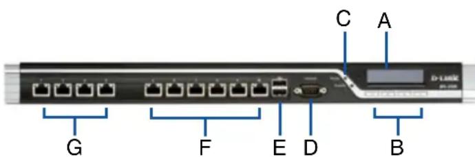
Figure 1. DFL-2560/2560G Front Panel
| Item F | Feature Description | |
| A LCD | Panel Used to display status and operation messages. | |
| B Keypad | These keys are used in conjunction with the messages on the LCD Panel. | |
| C LEDs | Power LED (top): Indicates that the NetDefend UTM firewall is powered on.System LED (bottom): Indicates the system status of the NetDefend UTM firewall | |
| D Console | Port Used to access the NetDefendOS Command Line Interface (CLI) via RS232 Cable. | |
| E USB | Ports (2) Reserved for future use. | |
| F | 10/100/1000Mbps Ethernet Ports* | The assigned numbers for the ports are 5 to 10 (from left to right). |
| G | 10/100/1000Mbps Ethernet Ports*(DFL-2560) | The assigned numbers for the ports are 1 to 4 (from left to right). |
| 1000Mbps SFP Port*(DFL-2560G) | ||
Table 1. DFL-2560/ 2560G Front Panel Descriptions
* Configurable Gigabit Ethernet ports with autosensing duplex and auto MDI/MDIX. When configuring one of the ports, reference the interface name that corresponds to the location of the port. For the default interface name bindings for each Ethernet port, see Table 2 "Default Interface Assignment".
DFL-2560/ 2560G Default Interface Settings
| Port | Interface Name | Interface Type | IP Address | Web-Based Mgmt |
| 1 | DMZ1 | Static IP | 172.17.100.254/24 | Disabled |
| 2 | DMZ2 | Static IP | 172.17.110.254/24 | Disabled |
| 3 | DMZ3 | Static IP | 172.17.120.254/24 | Disabled |
| 4 | DMZ4 | Static IP | 172.17.130.254/24 | Disabled |
| 5 | WAN1 DHC | P Client | N/A | Disabled |
| 6 | WAN2 | Static IP | 192.168.120.254/24 | Disabled |
| 7 | LAN1 | Static IP | 192.168.10.1/24 | Enabled |
| 8 | LAN2 | Static IP | 192.168.20.1/24 | Disabled |
| 9 | LAN3 | Static IP | 192.168.30.1/24 | Disabled |
| 10 | LAN4 | Static IP | 192.168.40.1/24 | Disabled |
Table 2. Default Interface Assignment
Note: D-Link NetDefend Firewalls only allow Web GUI access from the LAN1 port by default for security reasons. That means the Web GUI access is only allowed on port No. 7 of front plate by default for DFL-2560/DFL-2560G.
Device Status LEDs and Ethernet Port LEDs
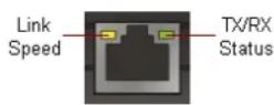
Figure 2. Ethernet RJ-45 Port LEDs
natural_image
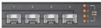
Front view of a server rack with four front-mounted units and an orange connection point (no visible text or labels)Figure 3. Ethernet SFP Port LEDs (DFL-2560G only)
The device LEDs show information about current device status. When the device is powered up, the POWER LED changes from off to solid green and the SYSTEM LED changes from off to solid green. Startup takes approximately one minute to complete. The Ethernet LEDs show the status of each Ethernet port. Table 3 lists the name, color, status, and description of each device LED.
Note: If you would like to turn the device off and on again, we recommend waiting a few seconds between shutting it down and powering it back on.
| Name Color Status - Description | ||
| Power Green Light Off - Device is powered off.Solid Green - Device is powered on. | ||
| System Green/ | Orange | Light Off - Device is powered off or is starting up.Solid Green - System is normal operation.Solid Orange - System failure or license lockdown. |
| TX/RX Status Green Light Off - No Link.Solid Green - Link present.Blinking Green - Port is sending or receiving data. | ||
| LINK Speed Green/Orange | Light Off - Port is operating at 10Mbps.Solid Green - Port is operating at 100Mbps.Solid Orange - Port is operating at 1000Mbps. | |
| Link and TX/RX for SFP port (DFL-2560G only) | Orange Light Off - No Link.Solid Orange - Link Present and operating at 1000Mbps.Blinking Orange - Port is sending or receiving data. | |
Table 3. Device Status LED Descriptions
LCD Keypad Controls During Boot-up
When you power on the DFL-2560/2560G, the LCD panel will display following message: "Press keypad to enter setup". Once you press any key on the keypad, it will lead you to enter the startup menu. If you don't press any keys after five seconds, the device will automatically continue the NetDefendOS boot-up procedure.
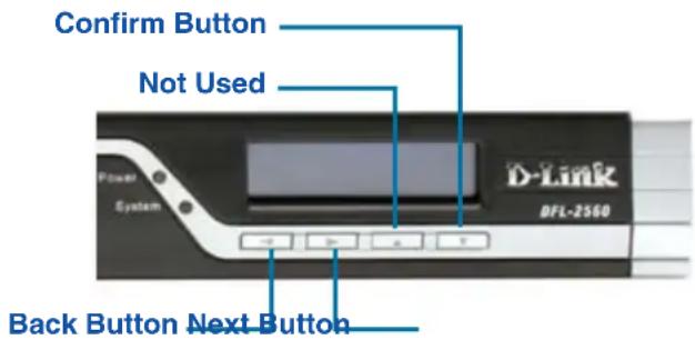
Figure 4. Button Definitions (During Boot-up)
If you press any keypad buttons within five seconds of powering the firewall on, the LCD panel will display three options:
If this option is selected, the system will initialize, start the NetDefendOS software, and load the saved configuration.
If this option is selected, the hardware will reset to factory defaults. This option will carry out the following steps:
Remove console security so there is no - console password.
Restore all NetDefendOS settings to their - default configuration
When you select this option, the system will restore all NetDefendOS settings to their default configuration. Other options, such as console security, will not be affected.
Note: Once you select "Reset Firewall" or "Reset Config" and confirm these options, all saved settings will be permanently erased.
LCD Keypad Controls After Boot-up
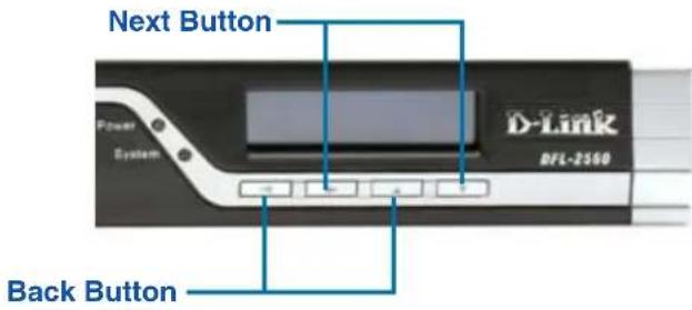
Figure 5. Button Definitions (After Boot-up)
Once the DFL-2560/2560G has completed its system startup routine, the LCD panel will be ready to display the device status information. You can use the keypad to select a desired display option. The following table lists the status information that can be displayed on the firewall's LCD panel.
| Item Description | |
| Model Name: Device model name | |
| System Status: System function status | |
| CPU Load: Connections: | CPU utilization and concurrent sessions |
| Total BPS: Concurrent traffic per second | |
| Total PPS: Concurrent packets per second | |
| Date: Current device date | |
| Time: Current device time | |
| Uptime: The amount of time since last restart | |
| Mem: System memory utilization | |
| IDS Sigs: IDS signature information | |
| Interface Name: (See Table 4.) | IP address for each interface |
| Core Version: Current firmware version | |
| CPU Temp. System Temp. | CPU and system temperature via on board sensor |
| Fan Status Fan speed | |
Table 4. Device Status Shown on LCD Panel
Installing and Connection
This chapter describes how to install a DFL-2560/DFL-2560G device in a standard 19-inch equipment rack and how to connect network and power cables to the device.
Before You Begin
Observe the following precautions to help prevent faults, equipment failures and injuries:
Before installation, always disconnect the - power supply.
Ensure that the room in which you operate - the device has adequate air circulation and that the room temperature does not exceed 40°C (104°F).
Allow 1 meter (3 feet) of clear space from the -front and back of the device.
Do not place the device in an equipment rack - frame that blocks the air vents on the sides of the chassis. Ensure that enclosed racks have fans and vented sides.
Correct any of the following hazardous - conditions before any installation: moist or wet floors, leaks, ungrounded/frayed power cables, or missing safety grounds.
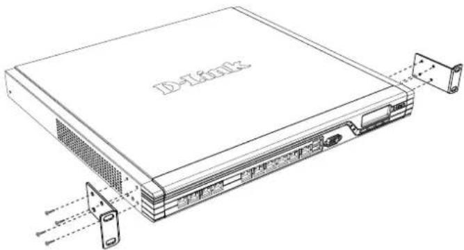
Installing Equipment
You can mount the DFL-2560/DFL-2560G device into a standard 19-inch equipment rack. To install an DFL-2560/DFL-2560G device into a rack:
- Attach the mounting brackets to each side of the chassis as shown in figure 6 and secure them with the provided screws.
natural_image
Line drawing of a network device chassis with ports and connectors (no text or symbols)Figure 6. Attaching Rack Mount Brackets
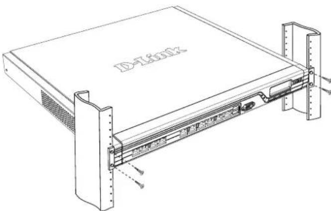
- Use the screws provided with the equipment rack to mount the device in the rack.
natural_image
Technical line drawing of a server rack unit with mounting brackets and ventilation slots (no text or symbols)Figure 7. Installation Using a Standard-sized Equipment Rack
Connecting Power and Turning On/Off
The AC Power cord shipped with the device connects the device to earth ground when plugged an AC grounding-type power outlet. The device must be connected to earth ground during normal operation.
To connect power to the device, plug one end of the AC power core into the AC power appliance inlet on the back panel of the device. Plug the other end into an AC power source.
Note: D-Link recommends the use of a surge protector with your power connection.
To power on the DFL-2560/2560G device, press the AC power switch on the rear panel to the on position. To power off the device, press the power switch to the off position.
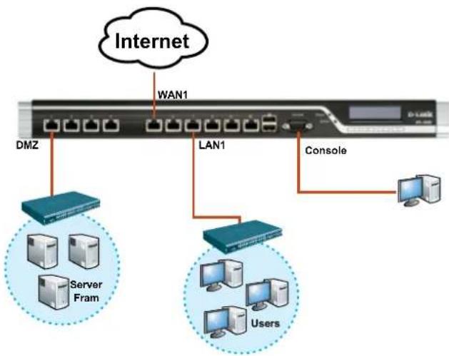
Connecting the Device to a Network
This section provides basic information about physically connecting the DFL-2560 or DFL-2560G to a network. Follow the steps below to connect the firewall as shown in Figure 8.
Connect an RJ-45 cable from the port 1. labeled 1 to the external router. The port No. 5 is pre-allocated to the WAN1 network segment.
Connect an RJ-45 cable from the port 2. labeled 1 to a switch in the DMZ1 network segment.
Connect an RJ-45 cable from the port 3. labeled 7 to a switch in the LAN1 network segment.
Connect an RS-232 cable from the console 4. port to a computer for CLI (Command Line Interface) management access.
flowchart
graph TD
    A["Internet"] --> B["WAN1"]
    B --> C["LAN1"]
    C --> D["DMZ"]
    C --> E["Server Fram"]
    C --> F["Users"]
    C --> G["Console"]
Figure 8. Basic Cabling Example
Initial Configuration
The NetDefendOS software is pre-installed on the DFL-2560/2560G device. When the device is powered on, it is ready to be configured. While the device has a default factory configuration that allows you to initially connect to the device, you must perform further configuration for your specific network requirements.
Using the WebUI
To use the WebUI, the workstation from which you are managing the device must initially be on the same subnetwork as the device.
| Browser Version | ||
 | Microsoft Internet Explorer | 6.0 or higher |
 | Mozilla Firefox 1.0 or higher | higher |
 | Netscape Navigator | 8.0 or higher |
Table 5. Browser Compatibility
To access the device with the WebUI:
Use an Ethernet cable to connect your 1. workstation to the port labeled 7, which is pre-allocated to LAN1.
Ensure your workstation is configured with 2. a static IP address in the 192.168.10.0/24 subnet.
Note: Disable pop-up blocking software or add the management IP address https://192.168.10.1 to your pop-up blocker's allow list.
Launch your browser; enter the IP 3. address for the LAN1 interface, then press Enter. (The factory default IP address is https://192.168.10.1)
Figure 9. Browser Address
Note: DFL-2560/2560G allows either HTTP or a secure HTTPS connections from any management host. However, for security reasons, only a secure HTTPS connection is allowed by default. For more information about configuring connections settings, please refer to the Firewall User Manual.
Step 4
Log into the NetDefend Firewall web interface.
The default login information is:
Username: admin
Password: admin
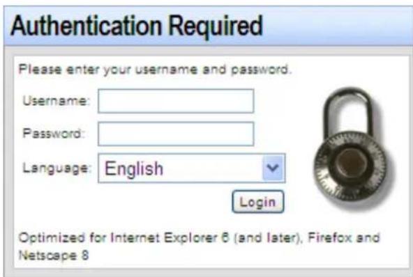
Figure 10. Authentication Message
Note: The Language drop-down menu allows you to select a language for the WebUI. By factory default, NetDefend Firewall only includes English. You may upload specific language files from within the WebUI for additional language support. At the moment, the Japanese, Russian, Simplified Chinese and Traditional Chinese language files are available.
Using a Console Connection (RS-232 DCE)
The NetDefend Firewall provides an RS-232 serial port that supports a connection to a computer or console terminal for monitoring and configuring the device. This port uses a male DB-9 connector, implemented as a data communication terminal equipment (DCE) connection.
To use the console port connection, you need the following equipment:
A terminal or a computer with both a serial 1. port and the ability to emulate a terminal.
A RS-232 cable with female DB-9 2. connector. (included in the package)
If your Laptop or PC doesn't have RS-232 3. connector, an adapter is required.
Note: DFL-2560/2560G does not come with an RS-232 adapter.
To establish a console connection:
Plug the female end of the supplied RS-232 1. cable directly to the console port on the Firewall, and tighten the captive retaining screws.
Connect the other end of the cable to 2. a terminal or to the serial connector of a computer running terminal emulation software. Use the following settings for terminal emulation software:
Baud rate: 9600
Data bits: 8
Parity: None
Stop bits: 1
Flow control: None
Once you have correctly set up the terminal, 3. switch on your device. A boot sequence will appear on the terminal screen.
Once the boot sequence completes, the 4. command prompt is displayed, the device is ready to be configured.
Finalizing the Configuration
After initial setup, please refer to the companion publications found in PDF format on the accompanying Reference CD for detailed instructions on configuring the DFL-2560/2560G.
D-Link NetDefend Firewall User Manual
This document describes the general operation and control of the NetDefendOS firmware, D-Link's proprietary operating system that drives and controls the NetDefend firewall. The User Manual includes detailed instructions regarding typical administrative tasks.
D-Link NetDefend Firewall Log Reference Guide
This document describes all log messages that might be generated by the NetDefendOS.
D-Link NetDefend Firewall CLI Reference Guide
This document describes all available text-based commands that can be used with the RS232 Console or SSH interface to configure the firewall.
Additional Information
In addition to the user manual, the Reference CD also includes many device configuration examples. Additional help is available through D-Link worldwide offices listed in the appendix of the User Manual or online. To learn more about D-Link security product products, please visit the website http://security.dlink.com.tw. For support, please visit the website http://support.dlink.com.tw, which will redirect you to your regional D-Link website.
Technical Support
United Kingdom (Mon-Fri) website: http://www.dlink.co.uk
FTP: ftp://ftp.dlink.co.uk Home Wireless/Broadband 0871 873 3000 (9.00am-06.00pm, Sat 10.00am-02.00pm) Managed, Smart, & Wireless Switches, or Firewalls 0871 873 0909 (09.00am- 05.30pm) (BT 10ppm, other carriers may vary.) Ireland (Mon-Fri)
All Products 1890 886 899 (09.00am-06.00pm, Sat 10.00am-02.00pm)
Phone rates: €0.05ppm peak, €0.045ppm off peak times

NETDEFEND
Handbuch zur Hardwareinstallation Firewall
natural_image
Line drawing of a D-Link computer interface unit with ports and connectors (no text or symbols)natural_image
Front view of a server rack with four front-mounted units and an orange connection point (no visible text or labels)natural_image
Line drawing of a D-Link server rack with ventilation slots and mounting bracket (no text or symbols)natural_image
Technical line drawing of a D-Link device with labeled ports and mounting brackets (no text or symbols beyond label)Stop bits (Stoppbit): 1
E-Mail: support@dlink.at
Schweiz: Web: http://www.dlink.ch
Telefon: +41(0)848 331100 0,08 CHF pro Minute
DFL-2560 / DFL-2560G
natural_image
Line drawing of a D-Link computer interface unit with ports and connectors (no text or symbols)Figure 1. Façade du DFL-2560/2560G
natural_image
Front view of a four-pin electronic device with four front panels and an external orange connector (no visible text or symbols)Figure 3. Ethernet Voyants du port SFP (DFL-2560G uniquement)
natural_image
Line drawing of a network device chassis with labeled ports and connectors (no text or symbols beyond label)natural_image
Technical line drawing of a D-Tech device chassis with mounting brackets and internal components (no text or symbols)Figure 10. Message d'authentication
Assistance Technique
DFL-2560 / DFL-2560G

natural_image
Line drawing of a D-Link computer interface unit with ports and connectors (no text or symbols)Acerca de esta guía
Figura 1. Panel frontal del DFL-2560/2560G
natural_image
Front view of a four-pin electronic device with orange connectors and labeled ports (no readable text or symbols)natural_image
Line drawing of a server rack with ventilation slots and connectors (no text or symbols)natural_image
Technical line drawing of a D-TLink rack unit with mounting brackets and internal components (no text or symbols)DFL-2560 / DFL-2560G

natural_image
Line drawing of a D-Link electronic device with ports and connectors (no text or symbols)Pannello frontale - DFL-2560 e DFL-2560G
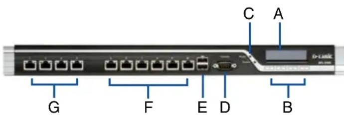
Figura 1. Pannello frontale di DFL-2560/ 2560G
natural_image
Front view of a rack-mounted server unit with four units and an orange connector (no visible text or labels)natural_image
Line drawing of a network device chassis with ports and connectors (no text or symbols)natural_image
Technical line drawing of a D-T601X rack device with mounting brackets and ventilation slots (no text or symbols)http://www.dlink.it/support
FCC EMI for Class A Statements
FCC Interference Information
This device complies with Part 15 of the FCC Rules. Operation is subject to the following two conditions:
(1) This device may not cause harmful interference, and (2) This device must accept any interference received, including interference that may cause undesired operation.
This equipment has been tested and found to comply with the limits for a Class A digital device, pursuant to Part 15 of the FCC Rules. These limits are designed to provide reasonable protection against harmful interference in a residential installation. This equipment generates, uses, and can radiate radio frequency energy and, if not installed and used in accordance with the instruction manual, may cause harmful interface to radio communication. Operation of this equipment in a residential area is likely to cause harmful interface in which cause the user will be required to correct the interface at his own expense.
FCC CAUTION:
Any changes or modifications not expressly approved by the party responsible for compliance could void the user's authority to operate this equipment.
CE WARNING Statement
CE EMI CLASS A WARNING
This is a class A product. In a domestic environment this product may cause radio interference in which case the user may be required to take adequate measures.

VCCI WARNING Statement
CAUTION: Risk of Explosion if Battery is replaced by an Incorrect Type. Dispose of Used Batteries According to the Instructions.
NOTES
NOTES