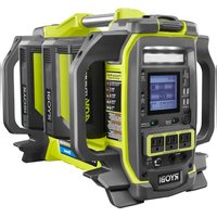
RYi1000 - Generator RYOBI - Free user manual and instructions
Find the device manual for free RYi1000 RYOBI in PDF.


User questions about RYi1000 RYOBI
0 question about this device. Answer the ones you know or ask your own.
Ask a new question about this device
Download the instructions for your Generator in PDF format for free! Find your manual RYi1000 - RYOBI and take your electronic device back in hand. On this page are published all the documents necessary for the use of your device. RYi1000 by RYOBI.
USER MANUAL RYi1000 RYOBI
Do not use E15 or E85 fuel (or fuel containing greater than 10% ethanol) in this product. It is a violation of federal law and will damage the unit and

natural_image
Line drawing of a portable electronic device with front panel and control buttons (no text or symbols)NEUTRAL FLOATING
WARNING: To reduce the
risk of injury, the user must read and understand the operator's manual before using this product.
SAVE THIS MANUAL FOR FUTURE REFERENCE
TABLE DES MATIÈRES
See this fold-out section for all of the figures referenced in the operator's manual.
text_image
Fig. 1 H J E D C B A I M L K N G F O P QA - On/off switch (commutateur marche/arrêt, interruptor de encendido y apagado)
B - Engine maintenance cover (couver pour l'entretien du moteur, cubierta de mantenimiento del motor)
C - Starter grip and rope (poignée du lanceur et corde, mango del arrancador y cuerda)
D - Choke lever (levier d'étrangleur, palanca del anegador)
E - Vented fuel cap (bouchon de carburant exhalé, tapa del tanque ventilación)
F - 120 volt AC 15 amp receptacles (prises 120 V c.a. 15 A, 120 V de ca 15 A receptáculos)
G - Ground terminal (borne de terre, terminal de conexión a tierra)
eH - Battery charging cable (câble du charge pile, cable para cargar la batería)
I - DC circuit breaker (disjoncteur d.c., disyuntor de circuito de d.c)
J - 12 Volt DC receptacle (prise de 12 V c.c, receptáculo de 12 V cc)
K - Low oil indicator (l'indicateur de bas niveau d'huile, luz de bajo nivel de lubricante)
L - Overload indicator (indicateur de surcharge, indicador de sobrecarga)
M- Power indicator (voyant d'alimentation, indicador de potencia)
N - Auto idle (mode de marche au ralenti automatique, ralentí automático)
O - Spark plug cover (couvercle de la bougie, cubierta de la bujía)
P - Carry handle (poignée de transport, mango de acarreo)
Q - Muffler with spark arrestor screen (silencieux avec écran pare-étincelles, silenciador con pantalla parachispas)
text_image
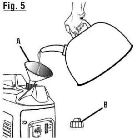
Technical diagram showing a hand pouring liquid into a car interior with labeled parts A and BA - Oil cap/dipstick (bouchon/ jauge d'huile, tapa de relleno de aceite/varilla medidora de aceite)
B - Funnel (entonnoir, embudo)
text_image
Fig. 5 A Bnatural_image
Technical line drawing of a mechanical component with labeled point A (no text or symbols beyond label)text_image
Technical diagram showing labeled parts A and B with directional arrows and a central component, likely from an engineering or mechanical drawing.A - Move choke lever right to start (tirer droite le levier d'étranglement pour démarrer, desplace derecha de la palanca del anegador para arrancar)
B - Move choke lever left to run (pousser gauche le levier d'étranglement pour la marche, desplace izquierda la palanca del anegador para poner en marcha)
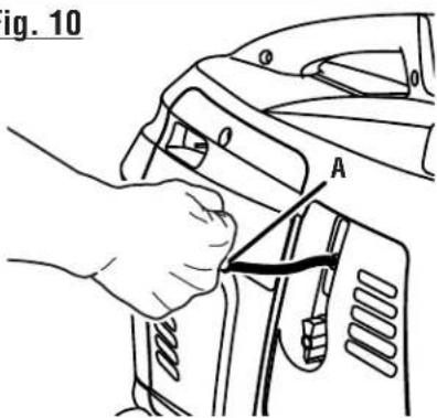
Fig. 10
text_image
ig. 10 AA - Starter grip and rope (poignée du lanceur et corde, mango del arrancador y cuerda)
Fig. 11
text_image
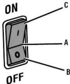
ON OFF A B CA - Auto idle (mode de marche au ralenti automatique, ralentí automático)
B - Off (arret, apagado)
C - On (marche, encendido)
Fig. 12
text_image
Diagram showing electrical connections with labeled components A, B, and C, likely illustrating a circuit or measurement setup.text_image
Technical diagram of a car interior showing labeled components A, B, C, and D for assembly or maintenance.text_image
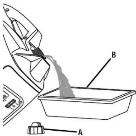
Technical diagram of a device with labeled components A and B, showing internal wiring and control panelA - Oil cap/dipstick (bouchon/ jauge d'huile, tapa de relleno de aceite/varilla medidora de aceite)
B - Container (conteneur, recipiente)
Fig. 15
text_image
Technical diagram of a vehicle's internal components with labeled parts A and BA - Spark plug cap (capuchon de bougie, tapa de la bujía)
B - Spark plug (bougie, bujía)
text_image
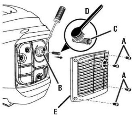
Technical diagram showing car engine component assembly with labeled parts A, B, C, D, E and a magnified view of the internal structure.A - Screws (vis, tornillos)
B - Muffler outlet (muffler outlet, recubrimiento del silenciador)
C - Spark arrestor (pare-étincelles, parachispas)
D - Wire brush (balai de roue, cepillo de alambre)
E - Rear panel (panneau arrière, panel posterior)
Fig. 17
text_image
Diagram showing a car interior with labeled parts A, B, and directional arrows indicating flow or movement.natural_image
Technical diagram of a mechanical assembly with labeled component A, showing internal components and a magnified inset (no text or symbols present)A - Carburetor drain screw (vis de vidange du carburateur, tornillo de drenaje del caburador)
To register your Ryobi product, please visit: www.ryobitools.com/
LOCATE GENERATOR AT LEAST 20 FT.\* AWAY TO REDUCE THE RISK OF CARBON MONOXIDE GETTING INSIDE THE HOME
* Minimum distance as recommended by U.S. Department of Health and Human Services Centers for Disease Control and Prevention (www.cdc.gov/co). Your specific home and/or wind conditions may require additional distance.

text_image
Exhaust (CO) Direct exhaust AWAY from all windows, doors, and vents. KEEP AT LEAST 20 FT.* AWAY Only use OUTSIDE and FAR AWAY from windows, doors, and vents.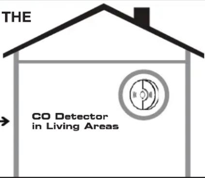
text_image
THE CO Detector in Living Areas
WARNING:
GROUNDING THE GENERATOR
If this generator will be used only with cord and plug-connected equipment, National Electric Code does not require that the unit be grounded. However, other methods of using the generator may require grounding to reduce the risk of shock or electrocution. Consult a qualified electrician, electrical inspector, or local agency having jurisdiction for local codes or ordinances to find out if grounding is needed in your situation before using the generator.
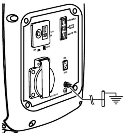
When grounding is required, the nut and ground terminal on the frame are used to connect the generator to a suitable ground source. The ground path should be made with #8 size wire. Connect the terminal of the ground wire between the lock washer and the nut, and tighten the nut fully. Connect the other end of the wire securely to a suitable ground source that is in contact with the soil for a minimum distance of 8 ft.
The National Electric Code contains several practical ways in which to establish a good ground source. If a steel or iron rod is used, it should be at least 5/8 in. diameter, and if a nonferrous rod is used, it should be at least 1/2 in. diameter and be listed as material for grounding. If a rock bottom is encountered before reaching a depth of 8 ft., drive
text_image
POWER USER LOAD LOW OUT 12V 3A ON OFF AC-120V ON OFFthe ground rod in at an angle of up to 45^ . If the rock bottom is again encountered, the rod can be buried in a trench that is at least 30 in. deep. In all cases, the upper end of the grounding rod should either be flush with (or below) the ground or must be otherwise protected from physical damage.
All electrical tools and appliances operated from this generator must be properly grounded by use of a third wire or be “Double Insulated.”
It is recommended to:
- Use electrical devices with 3-prong grounded plugs.
- Use an extension cord intended for outdoor use with a 3-pole receptacle and a 3-prong plug at opposite ends to ensure continuity of the ground protection from the generator to the appliance.
Check and adhere to all applicable federal, state, and local regulations relating to grounding specifications. Consult a qualified electrician or service personnel if the grounding instructions are not completely understood or if in doubt as to whether the generator is properly grounded.
IMPORTANT SAFETY INSTRUCTIONS

DANGER:
Carbon Monoxide. Using a generator indoors CAN KILL YOU IN MINUTES.
Generator exhaust contains high levels of carbon monoxide (CO), a poisonous gas you cannot see or smell. If you can smell the generator exhaust, you are breathing CO. But even if you cannot smell the exhaust, you could be breathing CO.
■ Never use a generator inside homes, garages, crawlspaces, or other partly enclosed areas. Deadly levels of carbon monoxide can build up in these areas. Using a fan or opening windows and doors does NOT supply enough fresh air.
■ ONLY use a generator outdoors and far away from open windows, doors, and vents. These openings can pull in generator exhaust.
Even when you use a generator correctly, CO may leak into the home. ALWAYS use a battery-powered or battery-backup CO alarm in the home.
If you start to feel sick, dizzy, or weak after the generator has been running, move to fresh air RIGHT AWAY. See a doctor. You could have carbon monoxide poisoning.

WARNING:
Read and understand all instructions. Failure to follow all instructions listed below could result in electrocution, fire, and/or carbon monoxide poisoning, which can cause death or serious injury.

WARNING:
In some applications, National Electric Code requires generator to be grounded to an approved earth ground. Before using the ground terminal, consult a qualified electrician, electrical inspector, or local agency having jurisdiction for local codes or ordinances that apply to the intended use of the generator.
SAVE THESE INSTRUCTIONS
This manual contains important instructions for this product that should be followed during installation and maintenance of the generator.
- Do not connect to a building's electrical system unless the generator and transfer switch have been properly installed and the electrical output has been verified by a qualified electrician. The connection must isolate the generator power from utility power and must comply with all applicable laws and electrical codes.
■ Do not allow children or untrained individuals to use this unit.
■ Do not start or operate the engine in a confined space, building, near open windows, or in other unventilated space where dangerous carbon monoxide fumes can collect. Carbon monoxide, a colorless, odorless, and extremely dangerous gas, can cause unconsciousness or death.
- Keep all bystanders, children, and pets at least 10 feet away.
■ Wear sturdy and dry shoes or boots. Do not operate while barefoot.
■ Do not operate generator when you are tired or under the influence of drugs, alcohol, or medication.
- Keep all parts of your body away from any moving parts and all hot surfaces of the unit.
■ Do not touch bare wire or receptacles.
■ Do not use generator with electrical cords which are worn, frayed, bare, or otherwise damaged.
■ Before storing, allow the engine to cool for 30 minutes and drain fuel from the unit.
■ Do not operate or store the generator in rain, snow, or wet weather.
■ Store the generator in a well-ventilated area with the fuel tank empty. Fuel should not be stored near the generator.
■ Empty fuel tank, turn the On/Off switch to OFF and restrain the unit from moving before transporting in a vehicle.
■ To reduce the risk of fire and burn injury, handle fuel with care. It is highly flammable.
■ Do not smoke while handling fuel.
■ Store fuel in a container approved for gasoline.
■ Position the unit on level ground, stop engine, and allow to cool for five minutes before refueling.
■ Loosen fuel cap slowly to release pressure and to keep fuel from escaping around the cap.
■ Tighten the fuel cap securely after refueling.
■ Wipe spilled fuel from the unit.
■ Never attempt to burn off spilled fuel under any circumstances.
■ Generators vibrate in normal use. During and after the use of the generator, inspect the generator as well as extension cords and power supply cords connected to it for damage resulting from vibration. Have damaged items repaired or replaced as necessary. Do not use plugs or cords that show signs of damage such as broken or cracked insulation or damaged blades.
For power outages, permanently installed stationary generators are better suited for providing back-up power to the home. Even a properly connected portable generator can become overloaded. This may result in overheating or stressing the generator components, possibly leading to generator failure.
IMPORTANT SAFETY INSTRUCTIONS
■ Use only authorized replacement parts and accessories and follow instructions in the Maintenance section of this manual. Use of unauthorized parts or failure to follow maintenance instructions may create a risk of shock or injury.
- Maintain the unit per maintenance instructions in this Operator's Manual.
- Inspect the unit before each use for loose fasteners, fuel leaks, etc. Replace damaged parts.
SPECIFIC SAFETY RULES

WARNING:
When this generator is used to supply a building wiring system: generator must be installed by a qualified electrician and connected to a transfer switch as a separately derived system in accordance with NFPA 70, National Electrical Code. The generator shall be connected through a transfer switch that switches all conductors other than the equipment grounding conductor. The frame of the generator shall be connected to an approved grounding electrode. Failure to isolate the generator from power utility can result in death or injury to electric utility workers.
■ Do not use this generator to provide power for emergency medical equipment or life support devices.
■ Exhaust contains poisonous carbon monoxide, a colorless, odorless gas. Breathing exhaust can cause loss of consciousness and can lead to death. If running in a confined or partially-enclosed area, the air may contain a dangerous amount of carbon monoxide. To keep exhaust fumes from building up, always provide adequate ventilation.
■ Always use a battery-powered carbon monoxide detector when running the generator. If you begin to feel sick, dizzy, or weak while using the generator, shut it off and get to fresh air immediately. See a doctor. You may have carbon monoxide poisoning.
- Place the generator on a flat, stable surface with a slope of no more than 4^ .
■ Operate outdoors in a well-ventilated, well-lit area isolated from working areas to avoid noise interference.
■ Operating the generator in wet conditions could result in electrocution. Keep the unit dry.
- Keep the generator a minimum of 3 feet away from all types of combustible material.
■ Do not operate generator near hazardous material.
■ Do not operate generator at a gas or natural gas filling station.
■ Do not touch the muffler or cylinder during or immediately after use; they are HOT and will cause burn injury.
This generator has a neutral floating condition. This means the neutral conductor is not electrically connected to the frame of the machine.
- Do not allow the generator's gas tank to overflow when filling. Fill to 1 in. below the top neck of the gasoline tank to allow for fuel expansion. Do not cover the fuel tank cap when the engine is running. Covering the fuel tank cap during use may cause engine failure and/or damage to the tool.
■ Do not smoke when filling the generator with gasoline.
■ Shut down the engine and allow to cool for five minutes before adding gasoline or lubricant to the generator.
■ Do not remove the oil dipstick or the fuel tank cap when the engine is running.
■ Pay close attention to all safety labels located on the generator.
- Keep children a minimum of 10 feet away from the generator at all times.
■ The unit operates best in temperatures between 23^ F and 104^ F with a relative humidity of 90% or less.
- Operating voltage and frequency requirement of all electronic equipment should be checked prior to plugging them into this generator. Damage may result if the equipment is not designed to operate within a +/- 10% voltage variation, and +/- 3 hz frequency variation from the generator name plate ratings.
■ For outdoor use only.
■ Save these instructions. Refer to them frequently and use them to instruct others who may use this product. If you loan someone this product, loan them these instructions also.
SYMBOLS
| The following signal words and meanings are intended to explain the levels of risk associated with this product. SYMBOL SIGNAL MEANING | ||
 | DANGER: | Indicates an imminently hazardous situation, which, if not avoided, will result in death or serious injury. |
 | WARNING: | Indicates a potentially hazardous situation, which, if not avoided, could result in death or serious injury. |
 | CAUTION: | Indicates a potentially hazardous situation, which, if not avoided, may result in minor or moderate injury. |
| NOTICE: | (Without Safety Alert Symbol) Indicates important information not related to an injury hazard, such as a situation that may result in property damage. | |
| Some of the following symbols may be used on this product. Please study them and learn their meaning. Proper interpretation of these symbols will allow you to operate the product better and safer. SYMBOL NAME DESIGNATION/EXPLANATION | ||
 | Safety Alert Indicates a potential | personal injury hazard. |
 | Read Operator's Manual | To reduce the risk of injury, user must read and understand operator's manual before using this product. |
 | Wet Conditions Alert Do not expose to rain or use in damp locations. | |
 | Electric Shock | Failure to use in dry conditions and to observe safe practices can result in electric shock. |
 | Toxic Fumes | Running generator gives off carbon monoxide, an odorless, color-less, poison gas. Breathing carbon monoxide can cause nausea, fainting, or death. |
 | Fire/Explosion | Fuel and its vapors are extremely flammable and explosive. Fire or explosion can cause severe burns or death. |
 | Hot Surface | To reduce the risk of injury or damage, avoid contact with any hot surface. |
 | Lifting Hazard | To reduce the risk of serious injury, avoid attempting to lift the generator alone. |
 | Ground | Consult with local electrician to determine grounding requirements before operation. |
SYMBOLS
| Some of the following symbols may be used on this product. Please study them and learn their meaning. Proper interpretation of these symbols will allow you to operate the product better and safer. | ||
| SYMBOL NAME DESIGNATION/EXPLANATION | ||
| V Volts Voltage | ||
| A Amperes Current | ||
| Hz Hertz Frequency (cycles per second) | ||
| W Watt Power | ||
| hrs Hours Time | ||
| gal Gallon Volume | ||
| qt Quart Volume | ||
SAFETY LABELS
The information below can be found on the generator. For your safety, please study and understand all of the labels before starting the generator.
If any of the labels come off the unit or become hard to read, contact an authorized service center for replacement.
■ You WILL be KILLED or SERIOUSLY HURT if you do not follow the Operator's Manual instructions.
■ Risk of Fire. Do not add fuel while the product is operating.
■ Generator is a potential source of electric shock. Do not expose to moisture, rain, or snow. Do not operate with wet hands or feet.
■ Exhaust contains poisonous carbon monoxide gas that can cause unconsciousness or DEATH. Operate in well-ventilated, outdoor areas away from open windows or doors.
DANGER
Using a generator indoors CAN KILL YOU IN MINUTES.
Generator exhaust contains carbon monoxide. This is a poison you cannot see or smell.

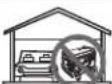
NEVER use inside a home or garage, EVEN IF doors and windows are open.
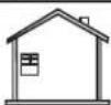

Only use OUTSIDE and far away from windows, doors, and vents.
DANGER
You WILL be KILLED or SERIOUSLY HURT if you do not follow the Operator's Manual instructions.
Exhaust contains poisonous carbon monoxide gas that can cause unconsciousness or DEATH. Operate in well ventilated, outdoor areas away from open windows or doors.
Risk of fire. Check for any fuel overflow or leaking. Stop the engine before refueling.
■ Do not expose to rain or use in damp locations.
■ Using a generator indoors CAN KILL YOU IN MINUTES. Generator exhaust contains carbon monoxide. This is a poison you cannot see or smell.
■ NEVER use inside a home or garage, EVEN IF doors and windows are open.
■ Only use OUTSIDE and far away from windows, doors, and vents.
FUEL WARNING
No smoking when filling with gasoline. Do not overfill. Full level is 1 in. below the top of the fuel neck. Stop the engine for five minutes before refueling to avoid the heat from the muffler igniting fuel vapors.
SYMBOLS
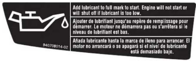
You must add lubricant before first operating the generator. Always check the lubricant level before each operation. The lubricant level should always register between the hatched areas on the dipstick. The unit is equipped with a sensor which will automatically shut off the engine if the lubricant level falls below a safe limit.
GROUNDING WARNING
This generator does not include a ground rod or copper wire. Call a qualified electrician for local grounding requirements.
HOT SURFACE WARNING
Do not touch the muffler or aluminum cylinder of the engine. They are very HOT and will cause severe burns. Don't put any flammable or combustible materials in the direct path of the exhaust.

WARNING
HOT SURFACE
AVERTISSEMENT
SURFACES CHAUDE
ADVERTENCIA
SUPERFICIE CALIENTE
▲ DANGER ▲ DANGER ▲ PELIGRO
Risk of Fire. Keep all objects at least 3 feet away from this machine. Heat from Muffler and Exhaust gases can ignite combustible objects.
While operating and storing, keep at least 3 feet of clearance on all sides of this product, including overhead. Allow a minimum of 30 minutes of "cool down" time before storage. Heat created by muffler and exhaust gases could be hot enough to cause serious burns and/or ignite combustible objects.
SPARK ARRESTOR
Operation of this equipment may create sparks that can start fires around dry vegetation. A spark arrestor may be required. The operator should contact local fire agencies for laws or regulations relating to fire prevention requirements.

Refer to the table below to ensure the cable size of the extension cords you use are capable of carrying the required load. Inadequate size cables can cause a voltage drop, which can damage the appliance and overheat the cord.
| Current in Amperes | Load in Watts Maximum Allowable Cord Length | ||||||
| At 120V | At 240V | #8 Wire | #10 Wire | #12 Wire | #14 Wire | #16 Wire | |
| 2.5 | 300 | 600 | 1000 ft. | 600 ft. | 375 ft. | 250 ft. | |
| 5 | 600 | 1200 | 500 ft. | 300 ft. | 200 ft. | 125 ft. | |
| 7.5 | 900 | 1800 | 350 ft. | 200 ft. | 125 ft. | 100 ft. | |
| 10 | 1200 | 2400 | 250 ft. | 150 ft. | 100 ft. | 50 ft. | |
| 15 | 1800 | 3600 | 150 ft. | 100 ft. | 65 ft. | ||
| 20 | 2400 | 4800 | 175 ft. | 125 ft. | 75 ft. | ||
| 25 | 3000 | 6000 | 150 ft. | 100 ft. | |||
| 30 | 3600 | 7200 | 125 ft. | 65 ft. | |||
| 40 | 4800 | 9600 | 90 ft. | ||||
ELECTRIC MOTOR LOADS
It is characteristic of common electric motors in normal operation to draw up to six times their running current while starting. This table may be used to estimate the watts required to start electric motors; however, if an electric motor fails to start or reach running speed, turn off the appliance or tool immediately to avoid equipment damage. Always check the requirements of the tool or appliance being used compared to the rated output of the generator.
| Motor Size (H.P.) Running Watts | Watts Required to Start Motor | ||||||
| Universal Capacitor Split Phase | |||||||
| 1/8 | 275 | N/A | 850 | 1200 | |||
| 1/6 | 275 | 600 | 850 | 2050 | |||
| 1/4 | 400 | 800 | 1050 | 2400 | |||
| 1/3 | 450 | 950 | 1350 | 2700 | |||
| 1/2 | 600 | 1000 | 1800 | 3600 | |||
| 3/4 | 850 | 1200 | 2600 | — | |||
| 1 | 1100 | N/A | 3300 | — | |||
NOTICE:
Operating voltage and frequency requirement of all electronic equipment should be checked prior to plugging them into this generator. Damage may result if the equipment is not designed to operate within a +/- 10% voltage variation, and +/- 3 hz frequency variation from the generator name plate ratings. To avoid damage, always have an additional load plugged into the generator if solid state equipment (such as a television set) is used. A power line conditioner is recommended for some solid state applications.
ELECTRICAL
GENERATOR CAPACITY
Make sure the generator can supply enough continuous (running) and surge (starting) watts for the items you will power at the same time. Follow these simple steps.
- Select the items you will power at the same time.
- Total the continuous (running) watts of these items. This is the amount of power the generator must produce to keep the items running. See the wattage reference chart at right.
- Estimate how many surge (starting) watts you will need. Surge wattage is the short burst of power needed to start electric motor-driven tools or appliances such as a circular saw or refrigerator. Because not all motors start at the same time, total surge watts can be estimated by adding only the item(s) with the highest additional surge watts to the total rated watts from step 2.
Example:
| Tool or Appliance | Running Watts* | Starting Watts* |
| Refrigerator | 700 | 1350 |
| Portable Fan | 40 | 120 |
| Laptop | 250 | 250 |
| 46 in. Flat Panel Television | 190 | 190 |
| Light (75 Watts) | 75 | 75 |
| 1255 Total Running Watts | 1350 Highest Starting Watts |
Total Running Watts 1255 Highest Starting Watts + 1350 Total Starting Watts Needed 2605
POWER MANAGEMENT
To prolong the life of the generator and attached devices, it is important to take care when adding electrical loads to the generator. There should be nothing connected to the generator outlets before starting its engine. The correct and safe way to manage generator power is to sequentially add loads as follows:
-
With nothing connected to the generator, start the engine as described later in this manual.
-
Plug in and turn on the first load, preferably the largest load you have.
-
Permit the generator output to stabilize (engine runs smoothly and attached device operates properly).
- Plug in and turn on the next load.
- Again, permit the generator to stabilize.
- Repeat steps 4 and 5 for each additional load.
Never add more loads than the generator capacity. Take special care to consider surge loads in generator capacity as previously described.
NOTICE:
Do not overload the generator's capacity. Exceeding the generator's wattage/amperage capacity may damage the generator and/or electrical devices connected to it.
| Application/Equipment | Estimated Running Watts* | Estimated* Starting Watts |
| Emergency / Home Standby | ||
| Lights (qty. 4 x 75 W) 300 300 | ||
| Refrigerator 700 1350 | ||
| 46 in. Flat Panel Television 190 190 | ||
| Satelite Receiver 250 250 | ||
| Portable Fan 40 120 | ||
| Heater 1300 1300 | ||
| Laptop 250 250 | ||
| Slow Cooker 270 270 | ||
| Radio 50 50 | ||
| Job Site | ||
| Electric Drill – 3/8 in. | 600 1000 | |
| Quartz Halogen Work Light | 1000 1000 | |
| Reciprocating Saw | 960 1920 | |
| Circular Saw – 7-1/4 in. | 1400 2300 | |
| Miter Saw – 10 in. | 1800 1800 | |
| Air Compressor – 1/4 HP | 970 1600 | |
| Airless Sprayer – 1/3 HP | 600 1200 | |
*Wattages listed are approximate. Check tool or appliance for actual wattage.
FEATURES
PRODUCT SPECIFICATIONS
ENGINE
Engine Type...... Single Cylinder (OHV) Four Cycle
Spark Plug....NHSP LD A7RTC
Engine Lubricant Volume....13.52 oz.
Fuel Volume 0.6 Gal.
GENERATOR
Rated Voltage....120 V AC/12 V DC
Rated Amps....7.5 A AC/7.5 A DC
Rated Running Watts 900 W
Starting Watts....1,000 W
Rated Frequency 60 Hz
KNOW YOUR GENERATOR
See Figure 1.
The safe use of this product requires an understanding of the information on the product and in this operator's manual as well as a knowledge of the project you are attempting. Before use of this product, familiarize yourself with all operating features and safety rules.
120 V AC RECEPTACLE
Your generator has a single phase, 60 Hz outlet that is a 120 Volt AC, 15 Amp receptacle. It can be used for operating appropriate appliances, electrical lighting, tools, and motor loads.
AIR FILTER
The air filter helps to limit the amount of dirt and dust drawn into the unit during operation.
AUTO IDLE SWITCH
The auto idle switch is used to control the speed of the engine and conserve fuel. When the switch is in the ON (I) position and no appliances are connected to the unit, the engine will idle. If an appliance is added, the engine speed will increase to power the item. If the appliance is removed, the engine will return to idle.
BATTERY CHARGING CABLE
The battery charging cable makes it easy to charge 12 Volt lead acid batteries with the generator.
NOTE: Only use battery charging cable to charge vented wet lead acid batteries.
CARRY HANDLE
The generator has a carry handle for easy transport.
CHOKE LEVER
The choke lever is used when starting the engine.
DC CIRCUIT BREAKER
The circuit breaker is provided to protect the generator against electrical overload.
DC RECEPTACLE
Your generator has a 12 volt, 7.5 Amp DC receptacle for charging lead acid batteries.

WARNING:
The 12 V DC receptacle is designed to charge vented wet lead acid batteries only. Other types of batteries could burst, causing personal injury and damage.
FUEL TANK
The fuel tank has a capacity of 0.6 gallon.
NOTE: The fuel flows from the fuel tank to the carburetor only when the on/off switch is in the ON (I) position.
GROUND TERMINAL
The ground terminal is used to assist in properly grounding the generator to help protect against electrical shock. Consult with a qualified local electrician for grounding requirements in your area.
LED DISPLAY
LEDs provide feedback to indicate whether the generator is in use, overloaded, or in need of lubricant.
LOW OIL SHUT DOWN PROTECTOR
The low oil sensor causes the engine to stop if the level of lubricant in the crankcase is insufficient.
OIL CAP/DIPSTICK
Remove the oil fill cap to check and add lubricant to the generator when necessary.
FEATURES
ON/OFF SWITCH
The on/off switch is used in combination with the starter grip and rope to start the generator. It is also used to turn the generator off.
STARTER GRIP AND ROPE
The starter grip and rope is used (along with the on/off switch) to start the generator's engine.
VENTED FUEL CAP
The generator has a fuel cap with a vent that can be opened and closed. During normal operation the vent should be in the OPEN (I) position.
ASSEMBLY
UNPACKING
This product has been shipped completely assembled.
- Carefully remove the product and any accessories from the box. Make sure that all items listed in the packing list are included.

WARNING:
Do not use this product if it is not completely assembled or if any parts appear to be missing or damaged. Use of a product that is not properly and completely assembled could result in serious personal injury.
■ Inspect the product carefully to make sure no breakage or damage occurred during shipping.
■ Do not discard the packing material until you have carefully inspected and satisfactorily operated the product.
■ If any parts are damaged or missing, please call 1-800-860-4050 for assistance.
PACKING LIST
Generator
Battery Charging Cable
Engine Lubricant (SAE 10W 30)
Funnel
Operator's Manual

WARNING:
If any parts are damaged or missing do not operate this product until the parts are replaced. Use of this product with damaged or missing parts could result in serious personal injury.

WARNING:
Do not attempt to operate the generator until assembly is complete. Failure to comply could result in possible serious personal injury.

WARNING:
Do not attempt to modify this product or create accessories not recommended for use with this product. Any such alteration or modification is misuse and could result in a hazardous condition leading to possible serious personal injury.
OPERATION

DANGER:
Carbon Monoxide. Using a generator indoors CAN KILL YOU IN MINUTES.
Generator exhaust contains high levels of carbon monoxide (CO), a poisonous gas you cannot see or smell. If you can smell the generator exhaust, you are breathing CO. But even if you cannot smell the exhaust, you could be breathing CO.
■ Never use a generator inside homes, garages, crawlspaces, or other partly enclosed areas. Deadly levels of carbon monoxide can build up in these areas. Using a fan or opening windows and doors does NOT supply enough fresh air.
■ ONLY use a generator outdoors and far away from open windows, doors, and vents. These openings can pull in generator exhaust.
Even when you use a generator correctly, CO may leak into the home. ALWAYS use a battery-powered or battery-backup CO alarm in the home.
If you start to feel sick, dizzy, or weak after the generator has been running, move to fresh air RIGHT AWAY. See a doctor. You could have carbon monoxide poisoning.

WARNING:
If this generator will be used only with cord and plug-connected equipment, National Electric Code does not require that the unit be grounded. However, other methods of using the generator may require grounding to reduce the risk of shock or electrocution. Consult a qualified electrician, electrical inspector, or local agency having jurisdiction for local codes or ordinances to find out if grounding is needed in your situation before using the generator.

WARNING:
Do not allow familiarity with this product to make you careless. Remember that a careless fraction of a second is sufficient to inflict serious injury.

WARNING:
Do not use any attachments or accessories not recommended by the manufacturer of this product. The use of attachments or accessories not recommended can result in serious personal injury.
NOTICE:
The spark arrestor on this product has not been evaluated by the USDA Forest Service and cannot be used on U.S. forest lands. In addition, product users must comply with Federal, State, and local fire prevention regulations. Check with appropriate authorities. Contact customer service to purchase a replacement spark arrestor.
NOTICE:
Before each use, inspect the entire product for damaged, missing, or loose parts such as screws, nuts, bolts, caps, etc. Tighten securely all fasteners and caps and do not operate this product until all missing or damaged parts are replaced. Please call 1-800-860-4050 or contact an authorized service center for assistance.
APPLICATIONS
This generator is designed to supply electrical power for operating compatible electrical lighting, appliances, tools, and motor loads.
■ Only use OUTSIDE and far away from windows, doors, and vents.
■ NEVER use inside a home or garage, EVEN IF doors and windows are open.
■ Always position the generator on a flat firm surface.
There may be General or State Occupational Safety and Health Administration (OSHA) regulations, local codes or ordinances that apply to the intended use of the generator.
Please consult a qualified electrician, electrical inspector, or the local agency having jurisdiction:
In some areas, generators are required to be registered with local utility companies.
If the generator is used at a construction site, there may be additional regulations which must be observed.
LED DISPLAY
See Figure 2.
Power:
The power indicator will light when the generator is on and the receptacles are operational.
NOTE: If the generator is overloaded, the power indicator light will go off.
Overload:
The overload indicator will blink when the generator's maximum wattage/amperage is reached. If the wattage/amperage capacity is exceeded, the LED will become solid and the unit's output will automatically shut down. To reset the generator, remove all loads from the generator and turn
OPERATION
the generator off. Restart the unit and add loads back to the generator one at a time being careful not to exceed the generators wattage rating.
Lubricant:
The oil indicator will light and the engine will automatically shut off whenever the lubricant level in the engine becomes low. The engine may not be restarted until sufficient engine lubricant has been added to the generator.
NOTE: It is normal for the indicator lights to illuminate and/or blink each time the engine is started. Once the engine warms up, the lights should default to the pattern above.
CHECKING/ADDING LUBRICANT
See Figures 3 - 4.
NOTICE:
Attempting to start the engine before it has been properly filled with lubricant will result in equipment failure.
Engine lubricant has a major influence on engine performance and service life. For general, all-temperature use, SAE 10W-30 is recommended. Always use a 4-stroke motor lubricant that meets or exceeds the requirements for API service classification SJ.
NOTE: Non-detergent or 2-stroke engine lubricants will damage the engine and should not be used.
■ Loosen the screw at the top of the engine maintenance cover. Remove cover and set aside.
■ Unscrew the oil cap/dipstick and remove.
■ Wipe dipstick clean and re-seat in hole; do not re-thread.
■ Remove dipstick again and check lubricant level. Lubricant level should fall between the minimum and maximum marks on the dipstick.
If level is low, add engine lubricant until the fluid level rises between the minimum and maximum marks on the dipstick.
■ Replace and secure the oil cap/dipstick.
- Replace the engine maintenance cover and reinstall the screw to secure.
USING FUEL STABILIZER
Fuel gets old, oxidizes, and breaks down over time. Adding a fuel stabilizer (not included) extends the usable life of fuel and helps prevent deposits from forming that can clog the fuel system. Follow fuel stabilizer manufacturer's directions for correct ratio of stabilizer to fuel.
■ Mix fuel stabilizer and gasoline prior to filling the tank by using a gas can or other approved fuel container and shaking gently to combine.
NOTE: To control the amount of fuel stabilizer being added to the engine, always mix fuel stabilizer with gasoline before fueling the tank rather than adding fuel stabilizer directly into the generator's fuel tank.
■ Replace and secure the fuel tank cap.
■ Start and run the engine for at least 5 minutes to allow stabilizer to treat the entire fuel system.
OXYGENATED FUELS
NOTICE:
Do not use E15 or E85 fuel (or fuel containing greater than 10% ethanol) in this product. It is a violation of federal law and will damage the unit and void your warranty.
Fuel system damage or performance problems resulting from the use of an oxygenated fuel containing more than the percentage of oxygenates stated below are not covered under warranty.
Ethanol. Gasoline containing up to 10% ethanol by volume (commonly referred to as E10) is acceptable. E15 and E85 are not.
CHECKING/ADDING FUEL
See Figures 5 and 8.

WARNING:
Gasoline and its vapors are highly flammable and explosive. To prevent serious personal injury and property damage, handle gasoline with care. Keep away from ignition sources, handle outdoors only, do not smoke while adding fuel, and wipe up spills immediately.
When adding gas to the generator, make sure the unit is sitting on a flat, level surface. If the engine is hot, let the generator cool for at least five minutes before adding gas. ALWAYS fill the fuel tank outdoors with the machine turned off.
■ Remove the fuel cap slowly.
■ Put the on/off switch in the ON (I) position.
■ Fill the fuel tank to 1 in. below the top of the fuel neck.
■ Replace and secure the fuel cap.
NOTE: Always use unleaded gasoline with a pump octane rating of 86 or higher. Never use old, stale, or contaminated gasoline, and do not use an oil/gas mixture. Do not allow dirt or water into the fuel tank. Do not use E85 fuel.
OPENING AND CLOSING VENTED FUEL CAP
See Figures 6 - 7.
The generator has a fuel cap with a vent that can be opened and closed.
■ To open the vent, rotate the fuel cap lever to the OPEN (I) position. The vent should be open during operation.
■ To close the vent, rotate the fuel cap lever to the CLOSED (O) position. The vent should be closed when the generator is not in use.
OPERATION
STARTING THE ENGINE
See Figures 7 - 11.
NOTICE:
On a level surface with the engine off, check the lubricant level before each use of the generator.
NOTE: If location of generator is not level, the unit may not start or may shut down during operation.
■ Unplug all loads from the generator.
■ Open the vent on the fuel cap by rotating the fuel cap lever to the OPEN (I) position.
■ Put the auto idle switch in the OFF (O) position.
■ Put the on/off switch in the ON (I) position.
NOTE: When the on/off switch is in the ON (I) position fuel will flow from the fuel tank to the engine.
■ Move the choke lever to the START position.
NOTE: If engine is warm, move the choke lever to the RUN position.
■ Pull the starter grip and rope until the engine runs (a maximum of 6 times).
NOTE: Do not allow the grip to snap back after starting; return it gently to its original place.
- Allow the engine to run for 15 - 30 seconds, then move the choke lever in to the RUN position.
NOTE: For quieter more efficient operation, place the auto idle switch in the ON (I) position.
STOPPING THE ENGINE
See Figures 7 and 9.
■ Remove any load from the generator.
■ Put the on/off switch in the OFF (O) position.
■ Close the vent on the fuel cap by rotating the fuel cap lever to the CLOSED (O) position.
NOTE: If the temperature is above 75^ F, leave the vent on the fuel cap open to relieve pressure.
To stop the engine in an emergency situation:
■ Put the on/off switch in the OFF (O) position.

WARNING:
While operating and storing, keep at least 3 feet of clearance on all sides of this product, including overhead. Allow a minimum of 30 minutes of “cool down” time before storage. Heat created by muffler and exhaust gases could be hot enough to cause serious burns and/or ignite combustible objects.
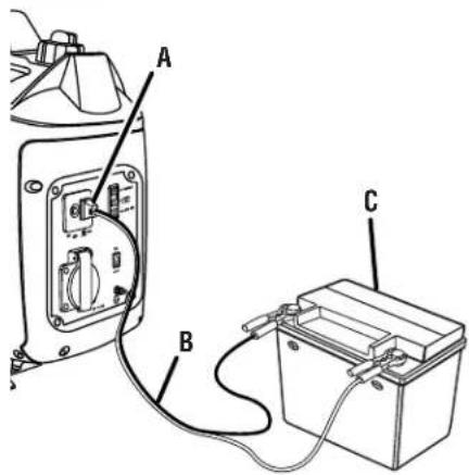
USING THE BATTERY CHARGING CABLE
See Figure 12.

WARNING:
The 12 V DC receptacle is designed to charge vented wet lead acid batteries only. Other types of batteries could burst, causing personal injury and damage.
NOTICE:
The 12 V DC receptacle provides continuous charge. Do not overcharge battery or leave battery unattended. Doing so may cause damage to the battery.
NOTICE:
Do not use the generator to jump start vehicles. Doing so could result in damage to the vehicle or it's electrical components.
■ Place the auto idle switch in the OFF (O) position.
■ Using the battery clamps, connect the battery charging cable assembly to the battery terminal. Connect the red wire to the positive (+) terminal first, then connect the black wire to the negative (−) terminal. Make sure all connections are secure.
NOTE: Be careful not to short across the terminals when installing. Shorting the terminals together can cause sparks, damage to the battery or generator, or even burns or explosions.
NOTE: To prevent short circuit, keep away from a metal surface during clamp connection.
■ Connect the battery charging cable assembly to the 12 V DC receptacle.
■ Start the generator.
NOTE: The AC receptacles can be used while the DC receptacle is in use.
■ The battery will become slightly warm to the touch while charging. This is normal and does not indicate a problem.
NOTE: Only use battery charging cable assembly to charge vented wet lead acid batteries.
■ When batteries become fully charged, disconnect the battery charging cable assembly from the battery. Disconnect the negative (black) wire first, then the positive (red) wire, being careful not to short across the terminals. Always abide by the safety warnings provided with the battery.
NOTE: Most batteries will be completely charged after 30 to 120 minutes. However, it is highly recommended that you refer to your battery manufacturer's instructions for specific charge times.
■ Unplug battery charging cable assembly and store for later use.
OPERATION
Specific modifications are needed for high-altitude operation for equipment operating in altitudes greater than 5000 feet above sea level. Please contact your authorized service center for important information regarding these modifications. Operating this engine without the proper altitude modification may increase the engine's emissions and decrease fuel economy and performance.
MAINTENANCE

WARNING:
When servicing, use only identical replacement parts. Use of any other parts could create a hazard or cause product damage.

WARNING:
Before inspecting, cleaning, or servicing the machine, shut off engine, wait for all moving parts to stop, and disconnect spark plug wire and move it away from spark plug. Allow 30 minutes of cool down time before performing any maintenance. Failure to follow these instructions can result in serious personal injury or property damage.
NOTICE:
Periodically inspect the entire product for damaged, missing, or loose parts such as screws, nuts, bolts, caps, etc. Tighten securely all fasteners and caps and do not operate this product until all missing or damaged parts are replaced. Please call 1-800-860-4050 or contact an authorized service center for assistance.
GENERAL MAINTENANCE
Keep the generator in a clean and dry environment where it is not exposed to dust, dirt, moisture, or corrosive vapors. Do not allow the cooling air slots in the generator to become clogged with foreign material such as leaves, etc.
Do not use a garden hose to clean the generator. Water entering the fuel system or other internal parts of the unit can cause problems that will decrease the life of the generator.
To clean the unit:
■ Use a soft bristle brush and/or vacuum cleaner to loosen and remove dirt and debris.
■ Clean air vents with low pressure air that does not exceed 25 psi.
■ Wipe the exterior surfaces of the generator with a damp cloth.
CHECKING/CLEANING AIR FILTER
See Figure 13.
For proper performance and long life, keep air filter clean.
■ Loosen the screw at the top of the engine maintenance cover. Remove cover and set aside.
■ Depress tabs on top and bottom of air filter cover. Remove cover and set aside.
■ Remove the air filter.
■ Wash the air filter with warm, soapy water. Rinse and squeeze to dry.
■ Reinstall the air filter.
- Remove the air filter.
- Wash the air filter with warm, soapy water. Rinse and squeeze to dry.
- Reinstall the air filter.
NOTE: Make sure the filter is seated properly inside the generator. Installing the filter incorrectly will allow dirt to enter the engine, causing rapid engine wear.
■ Reinstall the air filter cover by aligning the tabs on the cover with the slots in the generator housing.
■ Replace the engine maintenance cover and reinstall the screw to secure.
CHANGING ENGINE LUBRICANT
See Figure 14.
■ Loosen the screw at the top of the engine maintenance cover. Remove cover and set aside.
■ Remove the oil fill cap/dipstick.
■ Tilt the generator to the side and allow lubricant to drain from the oil fill hole into an approved container.
NOTE: Drain the lubricant while the engine is still warm but not hot. Warm lubricant will drain quickly and more completely.

WARNING:
Do not change engine lubricant while it is hot. Accidental contact with hot engine lubricant could result in serious burns.
■ Return the generator to an upright position and refill with lubricant following the instructions in the Checking/Adding Lubricant section previously in this manual. For amount of lubricant needed to refill, see Product Specifications earlier in this manual or the accompanying engine manual, if applicable.
■ Replace and secure the oil cap/dipstick.
■ Replace the engine maintenance cover and reinstall the screw to secure.
NOTE: Consult hazardous waste management guidelines in your area for the proper way to dispose of used lubricant.
SPARK PLUG REPLACEMENT
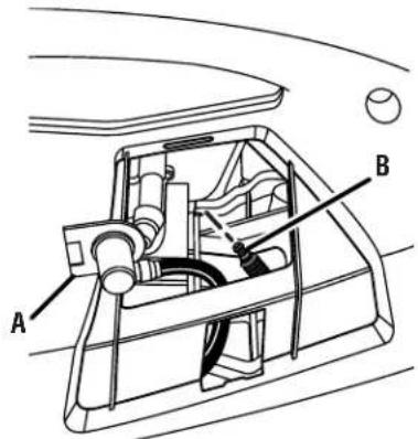
See Figure 15.
The spark plug must be properly gapped and free of deposits in order to ensure proper engine operation. To check:
■ Remove the spark plug cover.
■ Remove the spark plug cap.
MAINTENANCE
■ Clean any dirt from around base of spark plug.
■ Remove spark plug using spark plug wrench (not included).
■ Inspect spark plug for damage, and clean with a wire brush before reinstalling. If insulator is cracked or chipped, spark plug should be replaced. For replacement spark plug, see Product Specifications earlier in this manual or the accompanying engine manual, if applicable.
■ Measure plug gap. The correct gap is 0.024–0.028 in. (0.60-0.70 mm). To widen gap, if necessary, carefully bend the ground (top) electrode. To lessen gap, gently tap ground electrode on a hard surface.
- Seat spark plug in position; thread in by hand to prevent cross-threading.
NOTICE:
Be careful not to cross-thread the spark plug. Cross-threading will seriously damage the product.
■ Tighten with wrench (not included) to compress washer. If spark plug is new, use 1/2 turn to compress washer appropriate amount. If reusing old spark plug, use 1/8 to 1/4 turn for proper washer compression.
NOTE: An improperly tightened spark plug will become very hot and could damage the engine.
CLEANING THE EXHAUST PORT AND MUFFLER
Depending on the type of fuel used, the type and amount of lubricant used, and/or your operating conditions, the exhaust port and muffler may become blocked with carbon deposits. If you notice a power loss with your gas-powered products, you may need to remove these deposits to restore performance. We highly recommend that only qualified service technicians perform this service.
SPARK ARRESTOR
See Figure 16.
NOTICE:
The spark arrestor on this product has not been evaluated by the USDA Forest Service and cannot be used on U.S. forest lands. In addition, product users must comply with Federal, State, and local fire prevention regulations. Check with appropriate authorities. Contact customer service to purchase a replacement spark arrestor.
The spark arrestor must be cleaned or replaced every 50 hours or yearly to ensure proper performance of your product. Spark arrestors may be in different locations depending on the model purchased. Please contact your nearest service dealer for the location of the spark arrestor for your model.
To clean the spark arrestor:
■ Loosen the screws on the rear panel. Remove rear panel and set aside.
■ Remove the screw securing the spark arrestor in place.
■ Remove the spark arrestor and gently clean using a wire brush.
- Replace the spark arrestor and rear panel. Ensure that all screws are tightened securely.
DRAINING FUEL TANK/CARBURETOR
See Figures 17 - 18.
To help prevent gum deposits in the fuel system, drain the fuel from the tank and carburetor before storing.
DRAINING THE FUEL TANK:
NOTICE:
Remove all lubricant from the unit before draining the fuel tank. Failure to do so could cause damage to the unit.
■ Remove the fuel cap.
■ Tilt the generator and allow fuel to drain from the fuel tank into an approved container.
■ When the fuel has drained from the tank, replace the fuel cap.
DRAINING THE CARBURETOR:
■ Loosen the screw at the top of the engine maintenance cover. Remove cover and set aside.
■ Put the on/off switch in the OFF (O) position.
■ Position a suitable container under the carburetor drain screw to catch fuel; loosen the screw.
- Allow fuel to drain completely into container.
■ Retighten drain screw securely.
- Replace the engine maintenance cover and reinstall the screw to secure.
NOTE: Consult hazardous waste management guidelines in your area for the proper way to dispose of used fuel.
TRANSPORTING
■ Put the on/off switch in the OFF (O) position.
■ Close the vent on the fuel cap by rotating the fuel cap lever to the OFF (O) position.
■ Make sure engine and exhaust of unit is cool.
■ If transporting in a vehicle, drain the fuel tank, and securely restrain the generator.
■ Do not drop or strike unit or place under heavy objects.
MAINTENANCE
STORAGE
When preparing the generator for storage, allow the unit to cool for 30 minutes then follow the guidelines below.
| STORAGE TIME P | PRIOR TO STORING |
| Less than 2 months | Drain gasoline from tank and dispose of in a suitable container according to state and local ordinances. |
| 2 months to 1 year | Drain fuel from carburetor.Drain gasoline from tank and dispose of in a suitable container according to state and local ordinances. |
| 1 year or more ■ | Drain fuel from the carburetor.Remove spark plug.Drain gasoline from tank and dispose of in a suitable container according to state and local ordinances.Put a tablespoon of engine lubricant into the spark plug cylinder. Turn the engine slowly with the pull rope to distribute the lubricant.Reinstall spark plug.Change engine lubricant.After removal from storage:Fill with fresh gasoline. |
| NOTE: If storing gasoline in suitable container for later use, make sure gasoline has been treated with fuel stabilizer according to stabilizer manufacturer's instructions. | |
MAINTENANCE SCHEDULE
NOTE: If a separate engine manual is provided for this generator, please follow the maintenance schedule provided in the engine manual instead of the maintenance information listed below.
| Before each use | After 1st month or 20 hours of operation | Every 3 months or 50 hours of operation | Every 6 months or 100 hours of operation | Every year or after 300 hours of operation | |
| Check Engine Lubricant | ■ | ||||
| Change Engine Lubricant | ■ | ■ | |||
| Check Air Filter | ■ | ||||
| Clean Air Filter | ■ | ||||
| Change Air Filter | ■ | ||||
| Check/Adjust Spark Plug | ■ | ||||
| Replace Spark Plug | ■ | ||||
| Clean Fuel Tank and Filter^1 | ■ | ||||
| Check Fuel Hose | ■ | ■ | |||
| Check All Hose Connections | ■ | ■ | |||
| Inspect Fuel Tank Vapor Vent (If Equipped) | ■ | ■ | |||
| Inspect Carbon Canister (CARB Models Only) | ■ | ■ |
- These items should only be carried out by an authorized service center.
NOTE: Maintenance should be performed more frequently when generator is used in dusty areas.
When generator has exceeded the maximum figures specified in the table, maintenance should still be cycled according to the intervals of time or hours stated herein.
TROUBLESHOOTING
| PROBLEM POSSIBLE CAUSE SOLUTION | ||
| Engine will not start. On/Off switch is OFF (O).No fuel.Stale gasoline or water in gasoline.Lubricant level is low.Spark plug faulty, fouled, or improperly gapped.Choke lever is in RUN position.Engine stored without treating or draining gasoline, or refueled with bad gasoline.Dirty fuel filter. | Turn On/Off switch to ON (I).Fill fuel tank.Drain entire system and refill with fresh fuel.Engine is equipped with Low Oil Shutoff.If engine lubricant level is low, it must be filled before unit will start. Check engine lubricant level and fill, if necessary.Replace spark plug.Put the choke lever in the START position.Drain fuel and carburetor. Refuel with fresh gasoline.Contact authorized service center. | |
| Engine hard to start Water in gasoline. | Weak spark at spark plug. | Drain entire system and refill with fresh fuel.Contact authorized service center. |
| Engine lacks power. Dirty air filter. | Engine stored without treating or draining gasoline, or refueled with bad gasoline. | Check air filter. Clean or replace as needed.Drain fuel and carburetor. Refuel with fresh gasoline. |
| AC receptacle does not work. Generator | is overloaded.Item plugged in is defective. | Turn the generator off and remove all loads. Restart the unit.Try a different item. |
| DC receptacle does not work. Circuit pro | ptector engagedItem plugged in is defective. | Remove any load from the generator.Turn the auto idle switch to off, then depress the DC circuit breaker.Try a different item. |
| Generator makes a “spark knock” or “pinging” noise. | An occasional light “knocking” or “ping-ing” under heavy load is not a cause for concern. However, if the knocking or pinging occurs under normal load at a steady engine speed, the problem may be with the brand of gasoline being used. | Switch to a different brand of gasoline, making sure that the octane rating is 86 or higher. If problem continues, contact your nearest authorized service center. |
| If problem persists after trying the above solutions, contact your nearest authorized service center for assistance. | ||
| The following symptoms may indicate problems that will affect the emissions level of the unit:■ Hard starting or stalling after starting■ Rough idle■ Misfiring or backfiring under load■ Afterburning (backfiring)■ Black exhaust smoke or high fuel consumptionIf you encounter any of these symptoms, have the unit inspected and repaired by the nearest authorized service center. | ||
WARRANTY
LIMITED WARRANTY STATEMENT
Techtronic Industries North America, Inc., warrants to the original retail purchaser that this RYOBI® brand outdoor product is free from defect in material and workmanship and agrees to repair or replace, at Techtronic Industries North America, Inc.'s, discretion, any defective product free of charge within these time periods from the date of purchase.
■ Three years if the product is used for personal, family or household use;
■ 90 days, if used for any other purpose, such as commercial or rental.
This warranty extends to the original retail purchaser only and commences on the date of the original retail purchase.
Any part of this product found in the reasonable judgment of Techtronic Industries North America, Inc. to be defective in material or workmanship will be repaired or replaced without charge for parts and labor by an authorized service center for RYOBI® brand outdoor products (Authorized Ryobi Service Center).
The product, including any defective part, must be returned to an authorized Ryobi service center within the warranty period. The expense of delivering the product to the service center for warranty work and the expense of returning it back to the owner after repair or replacement will be paid by the owner. Techtronic Industries North America, Inc.'s, responsibility in respect to claims is limited to making the required repairs or replacements and no claim of breach of warranty shall be cause for cancellation or rescission of the contract of sale of any RYOBI® brand outdoor product. Proof of purchase will be required by the dealer to substantiate any warranty claim. All warranty work must be performed by an authorized service center.
This warranty is limited to ninety (90) days from the date of original retail purchase for any RYOBI® brand outdoor product that is used for rental or commercial purposes, or any other income-producing purpose.
This warranty does not cover any product that has been subject to abuse, misuse, neglect, negligence, accident, the effects of corrosion or erosion, or that has been operated in any way contrary to the operating instructions as specified in this operator's manual. This warranty does not apply to any damage to the product that is the result of improper maintenance or to any product that has been altered or modified. The warranty does not extend to repairs made necessary by normal wear or by the use of parts or accessories which are either incompatible with the RYOBI® brand outdoor product or adversely affect its operation, performance, or durability.
In addition, this warranty does not cover:
Tune-ups – Spark Plugs, Carburetor, Carburetor Adjustments, Ignition, Filters, Oil Change
Wear items – Recoil Starter Rope, Motor Brushes, Alternator Brushes, Cotter Pins, Wheels, a High Pressure Hose,
Spray Wand, Nozzles, Trigger Handle, Supply Hoses, Quick Couplers, Gaskets, Valves, Pistons, Pump Valve Assemblies, O-Rings, Water and Oil Seals, Detergent Tanks.
IMPORTANT: Some components not covered under this warranty may still be covered by a separate warranty issued by the engine manufacturer. Please see the Engine Manufacturer Warranty (if any) supplied with this product for further details.
The Company will not pay for repairs or adjustments to the Product, or for any costs or labor, performed without the Company's prior authorization.
Techtronic Industries North America, Inc., reserves the right to change or improve the design of any RYOBI® brand outdoor product without assuming any obligation to modify any product previously manufactured.
ALL IMPLIED WARRANTIES ARE LIMITED IN DURATION TO THE STATED WARRANTY PERIOD. ACCORDINGLY, ANY SUCH IMPLIED WARRANTIES INCLUDING MERCHANTABILITY, FITNESS FOR A PARTICULAR PURPOSE, OR OTHERWISE, ARE DISCLAIMED IN THEIR ENTIRETY AFTER THE EXPIRATION OF THE APPROPRIATE THREE-YEAR OR NINETY-DAY WARRANTY PERIOD. TECHTRONIC INDUSTRIES NORTH AMERICA, INC.'S, OBLIGATION UNDER THIS WARRANTY IS STRICTLY AND EXCLUSIVELY LIMITED TO THE REPAIR OR REPLACEMENT OF DEFECTIVE PARTS AND TECHTRONIC INDUSTRIES NORTH AMERICA, INC., DOES NOT ASSUME OR AUTHORIZE ANYONE TO ASSUME FOR THEM ANY OTHER OBLIGATION. SOME STATES DO NOT ALLOW LIMITATIONS ON HOW LONG AN IMPLIED WARRANTY LASTS, SO THE ABOVE LIMITATION MAY NOT APPLY TO YOU. TECHTRONIC INDUSTRIES NORTH AMERICA, INC., ASSUMES NO RESPONSIBILITY FOR INCIDENTAL, CONSEQUENTIAL, OR OTHER DAMAGES INCLUDING, BUT NOT LIMITED TO, EXPENSE OF RETURNING THE PRODUCT TO AN AUTHORIZED RYOBI SERVICE CENTER AND EXPENSE OF DELIVERING IT BACK TO THE OWNER, MECHANIC'S TRAVEL TIME, TELEPHONE OR TELEGRAM CHARGES, RENTAL OF A LIKE PRODUCT DURING THE TIME WARRANTY SERVICE IS BEING PERFORMED, TRAVEL, LOSS OR DAMAGE TO PERSONAL PROPERTY, LOSS OF REVENUE, LOSS OF USE OF THE PRODUCT, LOSS OF TIME, OR INCONVENIENCE. SOME STATES DO NOT ALLOW THE EXCLUSION OR LIMITATION OF INCIDENTAL OR CONSEQUENTIAL DAMAGES, SO THE ABOVE LIMITATION OR EXCLUSION MAY NOT APPLY TO YOU.
This warranty gives you specific legal rights, and you may also have other rights which vary from state to state.
This warranty applies this Ryobi® brand outdoor product manufactured by or for Techtronic Industries North America, Inc., and sold in the United States and Canada.
To locate your nearest Authorized Ryobi Service Center, dial 1-800-860-4050.
LIMITED ENGINE WARRANTY
Techtronic Industries North America, Inc. (herein "Techtronic Industries"), warrants that each new engine sold by it will be free, under normal use and service, from defects in material and workmanship for a period listed below from the date of sale to the original retail purchaser. Techtronic Industries obligation under this Limited Warranty shall be limited to the repair and replacement, at Techtronic Industries option, of any part or parts which upon examination is/are found, in Techtronic Industries judgment, to have been defective in material or workmanship. It shall be a condition of Techtronic Industries obligation under this Limited Warranty that Techtronic Industries, directly or through one of its Distributors or Service Centers authorized to service the particular engine involved, receive prompt notice of any warranty claim and that the engine or the part or parts claimed to be defective be promptly delivered, transportation prepaid, to such Distributor or Service Center for inspection and repair. All repairs qualifying under this Limited Warranty must be performed by Techtronic Industries or one of its authorized Distributors or Service Centers.
WARRANTY PERIODS:
158F Gasoline Engine (Private/Residential) Limited 2 year Warranty
158F Gasoline Engines (Commercial) Limited 90 Day Warranty
The repair or replacement of any part or parts under this Limited Warranty shall not extend the term of the engine warranty beyond the original term as set forth above.
LIMITATIONS AND EXCLUSIONS: This Limited Warranty shall not apply to:
- Repair required because of prolonged storage including damage caused by old or contaminated fuel in the fuel tank, fuel lines, or carburetor, sticky valves or corrosion and rust of engine parts.
- Repair required due to overheating. (Most often caused by overloaded or clogged or damaged or missing flywheel, fan, inlet air passages, cooling fins, or air shrouds.)
- Dirt or grit related wear caused by improper air cleaner maintenance (most often resulting in worn piston, piston
rings, cylinders, valves, valve guides, carburetor, or other internal components).
- Broken or scored parts caused by low oil level, dirty, or improper grade of oil.
- Engine tune-ups and normal maintenance service including, but not limited to, valve adjustment, normal replacement of service items, fuel, and lubricating oil, etc.
- Any engine which has been subject to negligence, misuse, accident, misapplication, or overspeeding.
- Any engine that has been installed, repaired, or altered by anyone in a manner which in Techtronic Industries sole judgment adversely affects its performance or reliability.
- Any engine which has been fitted with or repaired with parts or components not manufactured or approved by Techtronic Industries which in Techtronic Industries' sole judgment adversely affects its performance or reliability.
- Instances when normal use has exhausted the life of a component or an engine.
The customer is responsible for all transportation charges in connection with any warranty work.
Techtronic Industries reserves the right to modify, alter, or improve any engines or parts without incurring any obligation to modify or replace any engine or parts previously sold without such modification, alternation, or improvement.
No person is authorized to give any other warranty or to assume any additional obligation on Techtronic Industries' behalf unless made in writing and signed by an officer of Techtronic Industries.
THIS WARRANTY, TECHTRONIC INDUSTRIES OBLIGATION HERE UNDER, ARE IN LIEU OF ANY OTHER WARRANTIES OR OBLIGATIONS OF ANY KIND, EXPRESSED OR IMPLIED, INCLUDING ANY WARRANTIES OF MERCHANTABILITY OR FITNESS FOR A PARTICULAR PURPOSE. THERE ARE NO WARRANTIES WHICH EXTEND BEYOND THE DESCRIPTION ON THE FACE HERE-OF. TECHTRONIC INDUSTRIES SHALL IN NO EVENT BE LIABLE FOR ANY CONSEQUENTIAL OR INCIDENTAL DAMAGES.
IF YOU HAVE ANY QUESTIONS REGARDING YOUR WARRANTY RIGHTS AND RESPONSIBILITIES, CONTACT YOUR NEAREST AUTHORIZED RYOBI SERVICE CENTER AT 1-800-860-4050.
CALIFORNIA EMISSIONS CONTROL WARRANTY STATEMENT
YOUR WARRANTY RIGHTS AND OBLIGATIONS
The California Air Resources Board, United States Environmental Protection Agency (EPA), and Zhejiang ZhongJian Technology Co., Ltd. are pleased to explain the emissions control system warranty on your 2014/2015 small off-road engine (SORE). In California, new SOREs must be designed, built and equipped to meet the State's stringent anti-smog standards. Zhejiang ZhongJian Technology Co., Ltd. must warrant the emissions control system on your SOREs for the periods of time listed below provided there has been no abuse, neglect or improper maintenance of your SOREs.
Your emission control system may include parts such as the carburetor, fuel tanks, fuel caps, fuel lines, the ignition system, and catalytic converter. Also included may be hoses, belts, clamps, connectors and other emission-related assemblies.
For engines less than or equal to 80 cc only the fuel tank is subject to the evaporative emission control warranty requirements of this section. (California Only).
Where a warrantable condition exists, Zhejiang ZhongJian Technology Co., Ltd. will repair your small off-road engine at no cost to you including diagnosis, parts and labor.
MANUFACTURER'S WARRANTY COVERAGE
The emissions control system is warranted for two years. If any emissions-related part on your engine is defective, the part will be repaired or replaced by Zhejiang ZhongJian Technology Co., Ltd.
OWNER'S WARRANTY RESPONSIBILITIES
As the SORE owner, you are responsible for the performance of the required maintenance listed in your owner's manual. Zhejiang ZhongJian Technology Co., Ltd. recommends that you retain all receipts covering maintenance on your SORE, but Zhejiang ZhongJian Technology Co., Ltd. can not deny warranty solely for the lack of receipts or for your failure to ensure the performance of all scheduled maintenance.
As the SORE owner, you should however be aware that Zhejiang ZhongJian Technology Co., Ltd. may deny your warranty coverage if your SORE or a part has failed due to abuse, neglect, improper maintenance or unapproved modifications.
■ You are responsible for presenting your SORE to distribution center or service center authorized by Zhejiang ZhongJian Technology Co., Ltd. as soon as the problem exists. The warranty repairs should be completed in a reasonable amount of time, not to exceed 30 days.
If you have any questions regarding your warranty coverage, you should contact Zhejiang ZhongJian Technology Co., Ltd. customer service representative at 1-866-340-3912 or www.ryobitools.com.
DEFECTS WARRANTY COVERAGE
Adopted by the Air Resources Board, Zhejiang ZhongJian Technology Co., Ltd. warrants to the ultimate purchaser and each subsequent purchaser that the small off-road engine (SORE) (1) has been designed, built and equipped so as to conform with all applicable regulations; and (2) is free from defects in materials and workmanship that cause the failure of a warranted part to conform with those regulations as may be applicable to the terms and conditions stated below.
(a) The warranty period begins on the date the engine is delivered to an ultimate purchaser. The warranty period is two years.
(b) Subject to certain conditions and exclusions as stated below, the warranty on emissions related parts is as follows:
(1) Any warranted part that is not scheduled for replacement as required maintenance in your Owner's Manual is warranted for the warranty period stated above. If the part fails during the period of warranty coverage, the part will be repaired or replaced by Zhejiang ZhongJian Technology Co., Ltd. according to Subsection (4) below. Any such part repaired or replaced under warranty will be warranted for the remainder of the period.
(2) Any warranted part that is scheduled only for regular inspection in your Owner's Manual is warranted for the warranty period stated above. Any such part repaired or replaced under warranty will be warranted for the remaining warranty period.
(3) Any warranted part that is scheduled for replacement as required maintenance in your Owner's Manual is warranted for the period of time before the first scheduled replacement date for that part. If the part fails before the first scheduled replacement, the part will be repaired or replaced by Zhejiang ZhongJian Technology Co., Ltd. according to Subsection (4) below. Any such part repaired or replaced under warranty will be warranted for the remainder of the period prior to the first scheduled replacement point for the part.
(4) Repair or replacement of any warranted part under the warranty provisions herein must be performed at a warranty station at no charge to the owner.
(5) Notwithstanding the provisions herein, warranty services or repair will be provided at all of our distribution centers that are franchised to service the subject engines.
(6) The engine owner must not be charged for diagnostic labor that leads to the determination that a warranted part is in fact defective, provided that such diagnostic work is performed at a warranty station.
(7) Zhejiang ZhongJian Technology Co., Ltd. is liable for damages to other engine components proximately caused by a failure under warranty of any warranted part.
(8) Throughout the engine warranty period stated above, Zhejiang ZhongJian Technology Co., Ltd. will maintain a supply of warranted parts sufficient to meet the expected demand for such parts.
(9) Any replacement part may be used in the performance of any warranty maintenance or repairs and must be provided without charge to the owner. Such use will not reduce the warranty obligations of Zhejiang ZhongJian Technology Co., Ltd.
(10) Add-on or modified parts that are not exempted by the Air Resources Board may not be used. The use of any non-exempted add-on or modified parts by the ultimate purchaser will be grounds for disallowing a warranty claims. Zhejiang ZhongJian Technology Co., Ltd. will not be liable to warrant failures of warranted parts caused by the use of a non-exempted add-on or modified part.
(11) The manufacturer issuing the warranty shall provide any documents that describe that manufacturer's warranty procedures or policies within five working days of request by the Air Resources Board.
EMISSION WARRANTY PARTS LIST
The repair or replacement of any warranted part otherwise eligible for warranty coverage may be excluded from such warranty coverage if Zhejiang ZhongJian Technology Co., Ltd. demonstrates that the engine has been abused, neglected, or improperly maintained, and that such abuse, neglect, or improper maintenance was the direct cause of the need for repair or replacement of the part. That notwithstanding, any adjustment of a component that has a factory installed, and properly operating, adjustment limiting device is still eligible for warranty coverage. The following emissions warranty parts for each engine family list is covered.
(a) Fuel Metering System:
(1) Gasoline carburetor assembly and its internal components
(2) Carburetor gaskets
(3) Fuel tank
(4) Fuel line
(5) Fuel line fittings
(6) Clamps
(b) Air Induction System including:
(1) Intake pipe/manifold
(2) Air cleaner
(c) Ignition System including:
(1) Spark plug
(2) Ignition coil
(d) Catalytic Muffler Assembly (if so equipped) including:
(1) Muffler gasket
(2) Exhaust manifold
(3) Catalytic converter
(e) Crankcase Breather Assembly including:
(1) Breather connection tube
(f) Fuel tank evaporative emissions control system including:
(1) Purge valves
(2) Carbon canister
(3) Canister mounting brackets
(4) Fuel cap
(5) Fuel tank
(g) Miscellaneous items Used in Above Systems including:
(1) Switches
(2) Hoses, belts, connectors, and assemblies
(h) Air injection system
(1) Pulse valve
Using a generator indoors CAN KILL YOU IN MINUTES. Generator exhaust contains carbon monoxide. This is a poison you cannot see or smell.
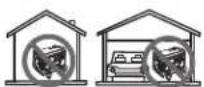
NEVER use inside a home or garage, EVEN IF doors and windows are open.
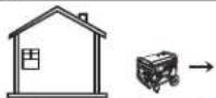
Only use OUTSIDE and far away from windows, doors, and vents.
DANGER
You WILL be KILLED or SERIOUSLY HURT if you do not follow the Operator's Manual instructions.
Exhaust contains poisonous carbon monoxide gas that can cause unconsciousness or DEATH. Operate in well ventilated, outdoor areas away from open windows or doors.
Risk of fire. Check for any fuel overflow or leaking. Stop the engine before refueling.
Risk of Fire. Keep all objects at least 3 feet away from this machine. Heat from Muffler and Exhaust gases can ignite combustible objects.
Operation of this equipment may create sparks that can start fires
around dry vegetation. A spark arrestor may be required. The operator should contact local fire agencies for laws or regulations relating to fire prevention requirements.
Using a generator indoors CAN KILL YOU IN MINUTES. Generator exhaust contains carbon monoxide. This is a poison you cannot see or smell.

NEVER use inside a home or garage, EVEN IF doors and windows are open.
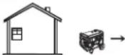
Only use OUTSIDE and far away from windows, doors, and vents.
DANGER
Risk of Fire. Keep all objects at least 3 feet away from this machine. Heat from Muffler and Exhaust gases can ignite combustible objects.
Operation of this equipment may create sparks that can start fires
around dry vegetation. A spark arrestor may be required. The operator should contact local fire agencies for laws or regulations relating to fire prevention requirements.
| Corriente en Amperios | Carga en vatios Longitud máxima permitida del cordón | ||||||
| A 120 V | A 240 V | Conduct. #8 | Conduct. #10 | Conduct. #12 | Conduct. #14 | Conduct. #16 | |
| 2,5 | 300 | 600 | 305 m (1000 pies) | 183 m (600 pies) | 114 m (375 pies) | 76 m (250 pies) | |
| 5 | 600 | 1200 | 152 m (500 pies) | 91 m (300 pies) | 61 m (200 pies) | 38 m (125 pies) | |
| 7,5 | 900 | 1800 | 107 m (350 pies) | 61 m (200 pies) | 38 m (125 pies) | 31 m (100 pies) | |
| 10 | 1200 | 2400 | 76 m (250 pies) | 46 m (150 pies) | 31 m (100 pies) | 15 m (50 pies) | |
| 15 | 1800 | 3600 | 46 m (150 pies) | 31 m (100 pies) | 20 m (65 pies) | ||
| 20 | 2400 | 4800 | 53 m (175 pies) | 38 m (125 pies) | 23 m (75 pies) | ||
| 25 | 3000 | 6000 | 46 m (150 pies) | 31 m (100 pies) | |||
| 30 | 3600 | 7200 | 38 m (125 pies) | 20 m (65 pies) | |||
| 40 | 4800 | 9600 | 27 m (90 pies) | ||||
CARGAS DE MOTORES ELÉCTRICOS
This product, its exhaust, and other substances that may become airborne from its use may contain chemicals, including lead, known to the State of California to cause cancer, birth defects, or other reproductive harm. Wash hands after handling.
PROPOSITION 65 DE L'ÉTAT DE CALIFORNIE

VERTISSEMENT :
RYOBI is a registered trademark of Ryobi Limited and is used pursuant to a license granted by Ryobi Limited.
Prior to requesting service or purchasing replacement parts, please obtain your model and serial number from the product data plate.
- MODEL NO. ____ SERIAL NO. ____
• HOW TO OBTAIN REPLACEMENT PARTS:
Replacement parts can be purchased online at www.ryobitools.com or by calling 1-800-860-4050. Replacement parts can also be obtained at one of our Authorized Service Centers.
• HOW TO LOCATE AN AUTHORIZED SERVICE CENTER:
Authorized Service Centers can be located online at www.ryobitools.com or by calling 1-800-860-4050.
• HOW TO OBTAIN CUSTOMER OR TECHNICAL SUPPORT:
To obtain Customer or Technical Support please contact us at 1-800-860-4050.

• PIÈCES ET SERVICE
1428 Pearman Dairy Road, Anderson, SC 29625 USA
1-800-860-4050 • www.ryobitools.com
A subsidiary of Techtronic Industries Co., Ltd. • OTC: TTNDY