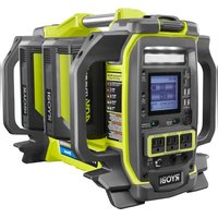
RYi1802B6 - Generator RYOBI - Free user manual and instructions
Find the device manual for free RYi1802B6 RYOBI in PDF.


User questions about RYi1802B6 RYOBI
0 question about this device. Answer the ones you know or ask your own.
Ask a new question about this device
Download the instructions for your Generator in PDF format for free! Find your manual RYi1802B6 - RYOBI and take your electronic device back in hand. On this page are published all the documents necessary for the use of your device. RYi1802B6 by RYOBI.
USER MANUAL RYi1802B6 RYOBI
Important Safety Instructions. 2
■ Specific Safety Rules. 3
Safety Rules For Charger. 4
Symbols. 5
Electrical 6-7
Features. 8
Assembly 9
Operation 9-12
■ Maintenance 13
Troubleshooting 13
Parts Ordering/Service......Back Page

WARNING: To reduce the risk of injury, the user must read and understand the operator's manual to use this product.
SAVE THIS MANUAL FOR FUTURE REFERENCE
TABLE DES MATIÈRES
See this fold-out section for all of the figures referenced in the operator's manual.
IMPORTANT SAFETY INSTRUCTIONS

WARNING:
READ AND UNDERSTAND ALL INSTRUCTIONS BEFORE USING THIS PRODUCT. Failure to follow all instructions listed below and on the machine may result in electric shock, fire, and/or serious personal injury.

WARNING:
When using this product, basic precautions should always be followed, including the following:
SAVE THESE INSTRUCTIONS
This manual contains important instructions for this product that should be followed during installation and maintenance of the power station.
To reduce the risk of injury, close supervision is necessary when this product is used near children.
- Do not put fingers, hands, or foreign objects into the product.
Use of an attachment not recommended or sold by product manufacturer may result in a risk of fire, electric shock, or injury to persons.
To reduce risk of damage to electric plug and cord, pull by the plug rather than cord when disconnecting charger from product.
- Do not use a battery pack or appliance that is damaged or modified. Damaged or modified batteries may exhibit unpredictable behavior resulting in fire, explosion or risk of injury.
- Do not operate the product with a damaged cord or plug, or a damaged output cable.
- Do not disassemble the product; take it to a qualified service person when service or repair is required. Incorrect reassembly may result in a risk of fire or electric shock.
To reduce the risk of electric shock, unplug the product from the outlet before attempting any instructed servicing.
To reduce risk of battery explosion, follow these instructions and those published by battery manufacturer and manufacturer of any equipment you intend to use in vicinity of the batteries. Review cautionary markings on the product.
- Do not expose the power station to rain or wet conditions. Water entering the power station will increase the risk of electric shock.
Do not disassemble the product.
For indoor use only.
Store product indoors and away from children.
As with all electrical devices, use caution when plugging and unplugging this unit into an outlet or plugging/ unplugging other devices into this unit. Do not force this unit into an outlet. Do not force plugs into this unit.
If this unit is used in a manner not specified by the manufacturer, the protection provided by this equipment may be impaired. - Operate this product using only the AC power type listed in the product specifications.
- Do not force a polarized plug (one prong larger than the other) into this product. Flip plug over and retry.
■ Risk of electric shock. When using a grounded appliance, this tool will not provide an electrical path to earth ground. - Do not power devices with damaged or frayed power cords.
- Never block air vents. Blocked vents may cause overheating. Product will automatically shut off when overheated.
- Keep product cool. Do not place near heat vents or in direct sunlight.
Use only with the provided charger or a charger approved by the manufacturer. - Do not use the product around flammable fumes and gasses, such as in the bilge of a boat or near propane tanks.
- Do not use the power station if it has been dropped or received a sharp blow. A damaged power source will increase the risk of fire.
Use only in a dry location. Do not allow any liquid to get inside the power station or charger. Do not submerge the power station or charger in any liquid. - Do not store the power station near fertilizers, gasoline, or other chemicals.
- Do not overload the power station. It must be used for powering devices less than the product rating.
For use with RYOBI 40V battery packs, see tool/appliance/battery pack/charger correlation supplement 988000-842.
BLUETOOTH® LICENSE STATEMENT
The Bluetooth® word mark and logos are registered trademarks owned by Bluetooth SIG, Inc. and any use of such marks by Techtronic Power Tools Technology Limited is under license. Other trademarks and trade names are those of their respective owners.
SPECIFIC SAFETY RULES

WARNING:
To reduce the risk of fire, do not connect to an AC load center (circuit breaker panel) having multi-wire branch circuits connected.
NEVER smoke or allow a spark or flame in vicinity of battery.
- Be extra cautious to reduce risk of dropping a metal tool onto product. It might spark or short-circuit battery or other electrical part that may cause explosion.
- Remove personal metal items such as rings, bracelets, necklaces, and watches when working with a battery. A battery can produce a short-circuit current high enough to weld a ring or the like to metal, causing a severe burn.
- When charging the internal battery, work in a well-ventilated area and do not restrict ventilation in any way.
Under abusive conditions, liquid may be ejected from the battery; avoid contact. If contact accidentally occurs,
flush with water. If liquid contacts eyes, additionally seek medical help. Liquid ejected from the battery may cause irritation or burns.
- Do not expose a power pack to fire or excessive temperature. Exposure to fire or temperature above 265^ may cause explosion.
- Have servicing performed by a qualified repair person using only identical replacement parts. This will ensure that the safety of the product is maintained.
This inverter has not been tested for use with medical devices. - Do not power life critical medical devices with this tool.
This product should never be hard wired into a circuit.
This product should never be wired into an AC distribution circuit.
Save these instructions. Refer to them frequently and use them to instruct others who may use this product. If you loan someone this product, loan them these instructions also.
SAVE THESE INSTRUCTIONS
SAFETY RULES FOR CHARGER

WARNING:
READ AND UNDERSTAND ALL INSTRUCTIONS.
Failure to follow all instructions listed below, may result in electric shock, fire and/or serious personal injury.
Before using battery charger, read all instructions and cautionary markings in this manual, on battery charger, battery, and product using battery to prevent misuse of the products and possible injury or damage.
- Do not use charger outdoors or expose to wet or damp conditions. Water entering charger will increase the risk of electric shock.
Use of an attachment not recommended or sold by the battery charger manufacturer may result in a risk of fire, electric shock, or injury to persons. Following this rule will reduce the risk of electric shock, fire, or serious personal injury.
- Do not abuse cord or charger. Never use the cord to carry the charger. Do not pull the charger cord rather than the plug when disconnecting from receptacle. Damage to the cord or charger could occur and create an electric shock hazard. If cord or charger is damaged, have the charger replaced by an authorized serviceman.
Make sure cord is located so that it will not be stepped on, tripped over, come in contact with sharp edges or moving parts or otherwise subjected to damage or stress. This will reduce the risk of accidental falls, which could cause injury, and damage to the cord, which could result in electric shock.
- Keep cord and charger from heat to prevent damage to housing or internal parts.
- Do not let gasoline, oils, petroleum-based products, etc. come in contact with plastic parts. They contain chemicals that can damage, weaken, or destroy plastic.
An extension cord should not be used unless absolutely necessary. Use of improper extension cord could result in a risk of fire and electric shock. If extension cord must be used, make sure:
a. That pins on plug of extension cord are the same number, size and shape as those of plug on charger.
b. That extension cord is properly wired and in good electrical condition; and
c. That wire size is large enough for AC ampere rating of charger as specified below:
Cord Length (Feet) 25' 50' 100
Cord Size (AWG) 16 16 16
NOTE: AWG = American Wire Gauge
- Do not operate charger with a damaged cord or plug, which could cause shorting and electric shock. If damaged, have the charger replaced by an authorized serviceman.
- Do not operate charger if it has received a sharp blow, been dropped, or otherwise damaged in any way. Take it to an authorized serviceman for electrical check to determine if the charger is in good working order.
- Do not disassemble charger. Take it to an authorized serviceman when service or repair is required. Incorrect reassembly may result in a risk of electric shock or fire.
Unplug charger from outlet before attempting any maintenance or cleaning to reduce the risk of electric shock. - Disconnect charger from the power supply when not in use. This will reduce the risk of electric shock or damage to the charger if metal items should fall into the opening. It also will help prevent damage to the charger during a power surge.
■ Risk of electric shock. Do not touch uninsulated portion of output connector or uninsulated battery terminal. - Do not use, store, or charge battery packs or products in locations where the temperature is less than -4^ or more than 113^ . Do not store outside or in vehicles.
- Save these instructions. Refer to them frequently and use them to instruct others who may use this tool. If you loan someone this tool, loan them these instructions also to prevent misuse of the product and possible injury.
IMPORTANT SAFETY INSTRUCTIONS
1. SAVE THESE INSTRUCTIONS - DANGER: TO REDUCE RISK OF FIRE OR ELECTRIC SHOCK, CAREFULLY FOLLOW THESE INSTRUCTIONS.
This manual contains important safety and operating instructions for battery charger RYi1802B6.
- Before using battery charger, read all instructions and cautionary markings on battery charger, battery, and product using battery.
- CAUTION: To reduce risk of injury, charge only the internal lithium-ion battery pack with this charger. Other types of batteries may burst, causing personal injury or damage.
SYMBOLS
| The following signal words and meanings are intended to explain the levels of risk associated with this product. | ||
| SYMBOL | SIGNAL | MEANING |
| A | DANGER: | Indicates a hazardous situation, which, if not avoided, will result in death or serious injury. |
| A | WARNING: | Indicates a hazardous situation, which, if not avoided, could result in death or serious injury. |
| A | CAUTION: | Indicates a hazardous situation, that, if not avoided, may result in minor or moderate injury. |
| NOTICE: | (Without Safety Alert Symbol) Indicates information considered important, but not related to a potential injury (e.g. messages relating to property damage). | |
| Some of the following symbols may be used on this product. Please study them and learn their meaning. Proper interpretation of these symbols will allow you to operate the product better and safer. SYMBOL NAME DESIGNATION/EXPLANATION | ||
| Safety Alert Indicates a potential | personal injury hazard. | |
| Read Operator's Manual | To reduce the risk of injury, user must read and understand operator's manual before using this product. | |
| Wet Conditions Alert | Do not expose battery, battery compartment, or electronic components to rain, water, or liquids. Do not charge battery or expose product to rain or damp locations. | |
| Electric Shock | Failure to use in dry conditions and to observe safe practices can result in electric shock. | |
| Recycle Symbol | This product uses lithium-ion (Li-ion) batteries. Local, state, or federal laws may prohibit disposal of batteries in ordinary trash. Consult your local waste authority for information regarding available recycling and/or disposal options. | |
| =DC Direct Current Type or a characteristic of current | ||
| ~ | Alternating Current Type of current | |
| ~ / ~ | Circuit Breaker | Indicates circuit breaker button must be fully pressed to reset circuit. |
| V Volts Voltage | ||
| A Amperes Current | ||
| Hz Hertz Frequency (cycles per second) | ||
| W Watt Power | ||
| hrs Hours | Time | |
ELECTRICAL
EXTENSION CORD CABLE SIZE
Refer to the table below to ensure the cable size of the extension cords you use are capable of carrying the required load. Inadequate size cables can cause a voltage drop, which can damage the appliance and overheat the cord.
| Current in Amperes | Load in Watts Maxim | um Allowable Cord Length | |||||
| At 120V | At 240V | #8 Wire | #10 Wire | #12 Wire | #14 Wire | #16 Wire | |
| 2.5 | 300 | 600 | 1000 ft. | 600 ft. | 375 ft. | 250 ft. | |
| 5 | 600 | 1200 | 500 ft. | 300 ft. | 200 ft. | 125 ft. | |
| 7.5 | 900 | 1800 | 350 ft. | 200 ft. | 125 ft. | 100 ft. | |
| 10 | 1200 | 2400 | 250 ft. | 150 ft. | 100 ft. | 50 ft. | |
| 15 | 1800 | 3600 | 150 ft. | 100 ft. | 65 ft. | ||
| 20 | 2400 | 4800 | 175 ft. | 125 ft. | 75 ft. | ||
| 25 | 3000 | 6000 | 150 ft. | 100 ft. | |||
| 30 | 3600 | 7200 | 125 ft. | 65 ft. | |||
| 40 | 4800 | 9600 | 90 ft. | ||||
ELECTRIC MOTOR LOADS
It is characteristic of common electric motors in normal operation to draw up to six times their running current while starting. This table may be used to estimate the watts required to start electric motors; however, if an electric motor fails to start or reach running speed, turn off the appliance or tool immediately to avoid equipment damage. Always check the requirements of the tool or appliance being used compared to the rated output of the product.
| Motor Size (H.P.) Running Watts | Watts Required to Start Motor | |||
| Universal Capacitor Split Phase | ||||
| 1/8 275 N/A | 850 1200 | |||
| 1/6 | 275 600 850 2050 | |||
| 1/4 | 400 800 1050 2400 | |||
| 1/3 | 450 950 1350 2700 | |||
| 1/2 | 600 1000 1800 3600 | |||
| 3/4 | 850 1200 2600 - | |||
| 1 1100 N/A | 3300 - | |||
NOTICE:
Operating voltage and frequency requirement of all electronic equipment should be checked prior to plugging them into this product. Damage may result if the equipment is not designed to operate within a + / - 10% voltage variation, and + / - 3Hz frequency variation from the product name plate ratings. To avoid damage, always have an additional load plugged into the product if solid state equipment (such as a television set) is used. A power line conditioner is recommended for some solid state applications.
ELECTRICAL
PRODUCT CAPACITY
Make sure the product can supply enough continuous (running) and surge (starting) watts for the items you will power at the same time. Follow these simple steps.
- Select the items you will power at the same time.
- Total the continuous (running) watts of these items. This is the amount of power the product must produce to keep the items running. See the wattage reference chart at right.
- Estimate how many surge (starting) watts you will need. Surge wattage is the short burst of power needed to start electric motor-driven tools or appliances such as a circular saw or refrigerator. Because not all motors start at the same time, total surge watts can be estimated by adding only the item(s) with the highest additional surge watts to the total rated watts from step 2.
Example:
| Tool or Appliance | Running Watts* | Starting Watts* |
| Inflator Pump 50 150 | 0 | |
| Laptop 250 0 | ||
| 46 in. Flat Panel Television | 190 0 | |
| Light (75 Watts) 75 | 0 | |
| 565 Total Running Watts | 150 Highest Starting Watts |
Total Running Watts 565
Highest Starting Watts + 150
Total Starting Watts Needed 715
CHARGE/RUNTIME CAPABILITY:
| Number of Charges* | |
| Phone | 36 |
| Laptop | 8.4 |
| Computer | 4.5 |
| Hours of Runtime* | |
| Modem/Router (15W) | 36 |
| TV (50W) | 8.4 |
| Garage Refrigerator (200W) | 4.5 |
*When using (2) 6Ah batteries.
POWER MANAGEMENT
To prolong the life of the product and attached devices, it is important to take care when adding electrical loads to the product. There should be nothing connected to the product outlets before starting. The correct and safe way to manage product power is to sequentially add loads as follows:
- With nothing connected, press the main power button, then press the AC output button to power the AC outlets.
- Plug in and turn on the first load, preferably the largest load you have.
- Make sure the attached device operates properly.
- Plug in and turn on the next load.
- Again, verify correct operation of the device.
- Repeat steps 4 and 5 for each additional load.
Never add more loads than the product capacity. Take special care to consider surge loads in product capacity as previously described.
NOTICE:
Do not overload the product's capacity. Exceeding the product's wattage/amperage capacity may damage the product and/or electrical devices connected to it.
| Application/Equipment | Estimated Running Watts* | Estimated Starting Watts* |
| Emergency / Home Standby | ||
| Lights (qty. 4 x 75 W) | 300 | 0 |
| Refrigerator | 600 | 780 |
| 46 in. Flat Panel Television | 190 | 0 |
| Satellite Receiver | 250 | 0 |
| Portable Fan | 40 | 120 |
| Heater | 1300 | 1300 |
| Laptop | 250 | 0 |
| Air Conditioner (10,000 BTU) | 600 | 1200 |
| Radio | 200 | 0 |
| Job Site | ||
| Electric Drill - 3/8 in. | 440 | 600 |
| Quartz Halogen Work Light | 1000 | 0 |
| Reciprocating Saw 960 | 960 | |
| Circular Saw - 7-1/4 in. | 1400 | 2300 |
| Miter Saw - 10 in. | 1800 | 1800 |
| Air Compressor - 1/4 HP | 970 | 1600 |
| Airless Sprayer - 1/3 HP | 600 | 1200 |
*Wattages listed are approximate. Check tool or appliance for actual wattage.
FEATURES
PRODUCT SPECIFICATIONS
Power Source. 40 Volt DC
Rated AC Output. 120 Volt AC, 60 Hz., 13.3 Amps
(15.0 Amps for 3 min. Max)
Rated DC Output:
USB-A. 5 Volts, up to 2.1 Amps
USB-C. .5/12/20 Volts, up to 3 Amps
Rated Output. 1,600 W (1,800 W for 3 min. Max)
Starting Watts. 3,000 W
Charger Input. (nominal) 120V/60Hz AC only, 80 W
Charging Time....Dependent on quantity and amp hour
capacity of battery pack(s)
Operating Temp. 32°-104°F
KNOW YOUR PRODUCT
See Figure 1.
The safe use of this product requires an understanding of the information on the product and in this operator's manual as well as a knowledge of the project you are attempting. Before use of this product, familiarize yourself with all operating features and safety rules.
120 V AC RECEPTACLES
Your product has three single phase, 60Hz outlets that are 120 Volt AC, 15 Amp receptacles. These can be used for operating appropriate appliances, electrical lighting, tools, and motor loads.
AC OUTPUT BUTTON
The AC output button is used to activate the 120V AC outlets when the power station is on. If an overload occurs, remove all loads, then press the AC output button again to reset.
CARRY HANDLE
The product is equipped with a carry handle for easy transport. The handle should be used to carry the product.
CHARGER
Using the charger before storing the power station helps keep the power station's battery charged and ready at all times.
GENCONTROL™ WITH BLUETOOTH®
The GENCONTROL monitoring system with Bluetooth® tracks battery level, runtime, load, and other functions.
LED TASK LIGHT
The LED task light can be used to provide general illumination for most work spaces.
MAIN POWER BUTTON
The main power button is used to turn the power station on and off. When turned on, power is available at the USB ports and to the LCD screen and LED task light. To use the AC outlets, the AC output button must also be turned on.
PARALLEL KIT TERMINALS
The non-polarized parallel kit terminals are used with a parallel kit that will allow products to be linked together to increase output.
NOTICE:
Connect the cables before turning the product on. Do not disconnect cables while the product is running. The product or the load may be damaged.
NOTE: Read and understand the parallel kit's instructions prior to use. Battery-powered inverters will not have a ground terminal; the ground wire will not be needed and can be left unconnected.
Parallel Kit .AUN9230TT
PROTECTIVE COVER
The protective cover can be used during use or storage for keeping dust, grease, and paint spatters off the unit. The convenient pocket provides storage for the charger.
USB PORTS
This product has four USB-A (5V, 2.1A) and two USB-C (5/12/20V, 3A) charging ports that will charge most USB-compatible devices.
ASSEMBLY
UNPACKING
This product has been shipped completely assembled.
- Carefully remove the product and any accessories from the box. Make sure that all items listed in the Packing List are included.

WARNING:
Do not use this product if it is not completely assembled or if any parts appear to be missing or damaged. Use of a product that is not properly and completely assembled could result in serious personal injury.
Inspect the product carefully to make sure no breakage or damage occurred during shipping.
- Do not discard the packing material until you have carefully inspected and satisfactorily operated the product.
If any parts are damaged or missing, please call 1-800-525-2579 for assistance.
PACKING LIST
Power Station
Protective Cover
Charger Cord and Adaptor
Operator's Manual

WARNING:
If any parts are damaged or missing do not operate this product until the parts are replaced. Use of this product with damaged or missing parts could result in serious personal injury.

WARNING:
Do not attempt to modify this product or create accessories not recommended for use with this product. Any such alteration or modification is misuse and could result in a hazardous condition leading to possible serious personal injury.
OPERATION

WARNING:
Risk of electric shock. When using a grounded appliance, this tool will not provide an electrical path to earth ground. Do not power devices with damaged or frayed power cords.

WARNING:
If this product will be used only with cord and plug-connected equipment, National Electric Code does not require that the product be grounded. This product is not suitable for any application that requires the product to be grounded. Consult a qualified electrician, electrical inspector, or local agency having jurisdiction for local codes or ordinances to find out if grounding is needed in your situation before using the product.

WARNING:
Do not allow familiarity with this product to make you careless. Remember that a careless fraction of a second is sufficient to inflict serious injury.

WARNING:
Do not use any attachments or accessories not recommended by the manufacturer of this product. The use of attachments or accessories not recommended can result in serious personal injury.
NOTICE:
Before each use, inspect the entire product for damaged, missing, or loose parts such as screws, nuts, bolts, caps, etc. Tighten securely all fasteners and caps and do not operate this product until all missing or damaged parts are replaced. Please contact customer service or a qualified service center for assistance.
APPLICATIONS
This product is designed to supply electrical power for operating compatible electrical lighting, appliances, tools, and motor loads.
There may be General or State Occupational Safety and Health Administration (OSHA) regulations, local codes or ordinances that apply to the intended use of the product.
Please consult a qualified electrician, electrical inspector, or the local agency having jurisdiction:
OPERATION
In some areas, products are required to be registered with local utility companies.
If the product is used at a construction site, there may be additional regulations which must be observed.
INSTALLING/REMOVING BATTERY PACKS
See Figure 2.
The power station has a total of four battery ports, but will function even if only one battery pack is installed. The more batteries installed, however, the greater the amount of power available and/or length of run or charge time provided, up to the full capacity noted in the Product Specifications section of this manual. For best performance, use at least two 5Ah or greater batteries.
Battery packs are shipped in a low charge condition and should be charged before first use.
To install:
- Attach the battery pack to the power source by aligning the raised ribs on the battery pack with the grooves on the power source. Press down on the battery pack until the latch snaps into place and the battery is fully seated.
Repeat to install additional battery packs as desired.
To remove:
- Locate the latch on the bottom of the battery pack and depress to release, then pull up on the battery pack to remove.
Install the desired number of battery packs.
NOTE: If not using all of the available battery slots, the location of the batteries installed does not matter and will not affect power station charging performance.
- Connect the charger cord to the power station, then plug the charger into a standard electrical outlet that is nominal 120/60Hz AC (typical U.S. household type circuit).
Once the charging cable is connected and plugged in, sequential charging of the batteries will begin.
NOTE: If connecting the charger immediately after using the power station at a high AC load, the battery temperature may be outside the acceptable charging range and cause the LCD display to show an error condition. If this occurs, charging will begin automatically once the battery temperature reaches an acceptable level.
BATTERY PORT LED FUNCTIONS
See Figure 2.
| BATTERY PACK LED ACTION | ||
| Power On | ||
| Without battery pack Solid Red Ready to charge battery pack. | ||
| Testing | ||
| Hot battery pack | Flashing Red | When battery pack reaches cooled temperature, charger begins charge mode. |
| Cold battery pack When battery pack reaches | battery pack reaches | s warmed temperature, charger begins charge mode. |
| Error | ||
| Error | Flashing Red and Green | Battery pack or charger error. |
| Deeply discharged Flashing Red Charger conditions battery until normal voltage is reached, then begins charge mode. | ||
| ·Try to repeat the conditions a second time by removing and reinstalling the battery pack. If the LED error status repeats a second time, try charging a different battery. ·If a different battery charges normally, dispose of the pack that received the error (see your battery pack manual for instructions). ·If a different battery also indicates error, the charger should be replaced. | ||
| Charging | ||
| Fast charging | Flashing Green | Battery is being charged. |
| Ready | ||
| Battery full | Solid Green | Charging is complete. |
OPERATION
GENERATOR CONDITION NOTIFICATIONS
See Figure 4.
| IF LCD DISPLAYS: THE CONDITION IS: TO RESOLVE: | ||
| HIGH TEMP or LOW TEMP when the battery is installed for charging.See figures 4a - 4b. | The battery you are charging is outside of the acceptable charging temperature range. | Allow the battery to reach acceptable temperature range. Battery may have to be removed from the port and reinstalled before charging will begin. |
| HIGH TEMPERATURE SHUTDOWN or LOW TEMPERATURE SHUTDOWN.See figures 4c - 4d. | The power station is outside of the acceptable operating temperature range. | Move the power station to a cooler or warmer area as needed and allow the unit to reach the acceptable temperature range. |
| HIGH TEMPERATURE WARNING or LOW TEMPERATURE WARNING PRESS RESET. See figures 4e - 4f. | The power station is nearing the maximum high or minimum low temperature acceptable to operate. | After allowing time for the power station to cool or warm to an acceptable temperature, press the reset button to continue operation. |
| LOW VOLTAGE SHUTDOWN.See figure 4g. | The power station's batteries are discharged. | Charge the power station. If condition persists, the power station's batteries should be replaced. |
| LOW VOLTAGE WARNING PRESS RESET.See figure 4h. | The power station's batteries do not have sufficient charge to run the connected devices. | Disconnect some of the devices. If condition persists, disconnect all devices and recharge the power station's batteries. |
An LED light located at the top of each battery port will indicate the status of each battery. Refer to the Battery Port LED Functions chart for a description of the lights. In addition to the LED indicator, the LCD screen will also provide information about the battery and charging status of the power station.
To power the product on:
Press and hold the main power button for two seconds to turn the product on. This will activate the LCD display and allow the USB charging ports and LED task light to be used.
NOTE: The main power button will illuminate when power to the unit is on.
To use the AC outlets:
After powering the product on, press and hold the AC output button to activate the AC outlets.
NOTE: For normal operation of the power station, the main power button and the AC output button (if using AC outlets) will be solid green and there will be one audible beep. If any other light pattern or beeps occur, refer to the Alert Functions chart that follows.
Sleep mode:
After 30 minutes of inactivity, the product will enter into sleep mode. In this state, the main power button LED will blink slowly and the LCD screen will turn off. All unit function is disabled to conserve power, but the Bluetooth® connection will remain active.
NOTE: Sleep mode will not occur if the AC output button is ON.
Press the main power button to end sleep mode.
Automatic shut-off:
The power station will automatically power off after 12 hours of inactivity. The Bluetooth® connection is also disabled at this time.
To manually turn the product off:
Press and hold the main power button for two seconds.

WARNING:
While operating, maintain clearance on all sides of this product. Do not block vents or allow the product to overheat.
OPERATION
GENCONTROL LCD DISPLAY
See Figure 6.
NOTE: The LCD display will not work unless the product is powered on.
Battery charge level:
The battery charge level indicator shows how much charge is remaining in the battery.
Load level:
The load level indicator shows the connected load. If the product is approaching the maximum wattage/amperage capacity, the indicator will blink. If the load level capacity is exceeded, the LCD display will show OVERLOADED. Remove all loads from the product and press the AC output button to reset (see fig. 5). Add loads back to the product one at a time, being careful not to exceed the product's wattage rating.
Run time:
The LCD display shows the run time based on when the unit was switched on.
Bluetooth®:
Once paired, the LCD display indicates whether or not the GENCONTROL app is connected through Bluetooth.
Input charging power:
The LCD display will show charging condition and full charge output.
USB CHARGING PORTS
See Figure 7.
NOTE: The main power button must be on for the USB ports to be active.
The USB-dedicated charging ports will charge most USB-compatible devices when used with the appropriate USB-A or USB-C cable (not provided).
For charging USB-C specific devices or other devices up to 3 amps, connect to the USB-C ports.
For MP3, cell phones, tablets, and other devices up to 2.1 amps, connect to the USB-A ports.
NOTE: The USB-dedicated charging port provides power only; it does not provide any communication capabilities. Suitable USB cables must be provided by the user.
USING THE LED TASK LIGHT
See Figure 8.
Press the task light control button once to turn the LED task light on. The light will illuminate on the high setting.
- Continue to press the button to cycle through other available settings — low, red, blinking red, and off.
PAIRING THE BLUETOOTH® PRODUCT
See Figure 9.
Installing the RYOBI™ GENCONTROL™ app on your Bluetooth® enabled iOS or Android device allows you to view and control many of the product's functions from your device.
- From the app store on your iOS or Android Bluetooth enabled device, locate and install the RYOBI™ GENCONTROL™ app.
- Open the app and follow the directions as shown in the GENCONTROL app.
NOTE: Make sure Bluetooth 假 is enabled on your device.
Press the main power button on the power station to turn the LCD display on.
Push and hold the "Hold to Pair" button to the right of the LCD panel on the product until the LCD panel displays "Pairing Mode."
The LCD screen on the product and the app on your device will indicate a successful pairing.
NOTE: If the product and app do not pair, make sure that "Pairing Mode" is displayed during the pairing process and that Bluetooth® is enabled on your device.
Press the menu icon in the top left corner of the app screen. This will show you the available features that can be controlled through the app.
USING THE PROTECTIVE COVER
See Figure 10.
The protective cover can be used during use or storage for keeping dust, grease, and paint spatters off the unit. The convenient pocket provides storage for the charger.
Install the cover over the power station as shown.
NOTE: Make sure the vent opening is to the back of the unit and the front panel is visible through the panel access cover.
- Snug the protective cover around the unit by adjusting the drawstring to secure it.
The panel access cover will unzip and allows you to adjust settings when using the protective cover.
The handle zipper can be opened for carrying or moving the unit.
NOTE: Always keep zippers closed during storage to keep dust and liquids from entering into the unit.
MAINTENANCE
NOTICE:
Periodically inspect the entire product for damaged, missing, or loose parts such as screws, nuts, bolts, caps, etc. Tighten securely all fasteners and caps and do not operate this product until all missing or damaged parts are replaced. Please contact customer service or a qualified service center for assistance.
GENERAL MAINTENANCE
Avoid using solvents when cleaning plastic parts. Most plastics are susceptible to damage from various types of commercial solvents and may be damaged by their use. Use clean cloths to remove dirt, dust, oil, grease, etc.

WARNING:
Do not at any time let brake fluids, gasoline, penetrating oils, etc., come in contact with plastic parts. Chemicals can damage, weaken, or destroy plastic which may result in serious personal injury.
STORING THE POWER STATION
Store indoors, without battery packs, in a dry, locked-up place, out of the reach of children. Store without battery packs unless actively charging/maintaining with the charger. Keep away from corrosive agents such as garden chemi cals and de-icing salts.
TROUBLESHOOTING
| PROBLEM POSSIBLE | CAUSE SOLUTION | |
| Unit will not power on. Battery is not charged. | Main power button released too quickly. | Charge battery. Press and hold main power button for two seconds. |
| AC receptacle does not work. AC output is not active or AC power button released too quickly. | Item plugged in is defective. | Press and hold the AC output button for two seconds. Try a different item. Remove loads and press the AC output button to reset. |
| AC receptacle does not work. AC output is not active or AC power button released too quickly. | ||
| AC receptacle does not work. AC output is not active or AC power button released too quickly. | ||
| AC receptacle does not work. AC output is not active or AC power button released too quickly. | ||
| AC receptacle does not work. AC output is not active or AC power button released too quickly. | ||
| AC receptacle does not work. AC output is not active or AC power button released too quickly. | Battery operating temperature must be between -4°F and 120°F. The unit cannot be powered on until the temperature reaches normal operating thresholds. Allow the power station to warm or cool as needed. Charge the battery. Units needs repair. Take to an authorized service center. | |
| AC receptacle does not work. AC output is not active or AC power button released too quickly. | ||
| AC receptacle does not work. AC output is not active or AC power button released too quickly. | ||
| AC receptacle does not work. AC output is not active or AC power button released too quickly. | ||
| AC receptacle does not work. AC output is not active or AC power button released too quickly. | Low or no battery charge. Battery fault. | |
| AC receptacle does not work. AC output is not active or AC power button released too quickly. | ||
| AC receptacle does not work. AC output is not active or AC power button released too quickly. | ||
| AC receptacle does not work. AC output is not active or AC power button released too quickly. | ||
| AC receptacle does not work. AC output is not active or AC power button released too quickly. | User exchanged batteries on the unit (removed and installed), at the same time. | Power Station load level should be below 40% (720 Watts) before exchanging batteries. |
| If problem persists after trying the above solutions, contact customer service or an authorized service center for assistance. | ||
FCC COMPLIANCE

WARNING:
Changes or modifications to this unit not expressly approved by the party responsible for compliance could void the user's authority to operate the equipment.
This device complies with part 15 of the FCC rules. Operation is subject to the following two conditions: (1) this device may not cause harmful interference, and (2) this device must accept any interference received, including interference that may cause undesired operation.
NOTE: The grantee is not responsible for any changes or modifications not expressly approved by the party responsible for compliance. Such modifications could void the user's authority to operate the equipment.
NOTE: This equipment has been tested and found to comply with the limits for a Class B digital device, pursuant to part 15 of the FCC Rules. These limits are designed to provide reasonable protection against harmful interference in a residential installation. This equipment generates, uses and can radiate radio frequency energy and, if not installed and used in accordance with the instructions, may cause harmful interference to radio communications. However, there is no guarantee that interference will not occur in a particular installation. If this equipment does cause harmful interference to radio or television reception, which can be determined by turning the equipment off and on, the user is encouraged to try to correct the interference by one or more of the following measures:
Reorient or relocate the receiving antenna.
Increase the separation between the equipment and receiver.
Connect the equipment into an outlet on a circuit different from that to which the receiver is connected.
Consult the dealer or an experienced radio/TV technician for help.
This device complies with Industry Canada license-exempt RSS standard(s). Operation is subject to the following two conditions: (1) this device may not cause interference, and (2) this device must accept any interference, including interference that may cause undesired operation of the device.
Under Industry Canada regulations, this radio transmitter may only operate using an antenna of a type and maximum (or lesser) gain approved for the transmitter by Industry Canada. To reduce potential radio interference to other users, the antenna type and its gain should be so chosen that the equivalent isotropically radiated power (e.i.r.p.) is not more than that necessary for successful communication.
SUPPLIER'S DECLARATION OF CONFORMITY
RYOBI 40 VOLT POWER STATION Model: RYi1802B6/RYi1802BT
The responsible party declares that this device complies with Part 15 of the FCC Rules. Operation is subject to the following two conditions: (1) this device may not cause harmful interference, and (2) this device must accept any interference received, including interference that may cause undesired operation.
Report No.:
| Responsible Party: One World Technologies |
| Address: 115 Innovation Way, Anderson, SC 29621 |
| Telephone: (864) 226-6511 |
| Fax: (864) 965-6274 |
| Printed Name/Title: John Collins / Director Regulatory |
| Signature: JBscu |
FCC ID: 2AMRBGBBLE01-NRF52
This product has a Five-year Limited Warranty for personal, family, or household use (90 days for business or commercial use).
For warranty details, visit www.ryobitools.com or call (toll free) 1-800-525-2579.
INSTRUCTIONS IMPORTANTES CONCERNANT LA SÉCURITÉ

AVERTISSEMENT :
LISEZ ET VEILLEZ À COMPRENDRE TOUTES LES INSTRUCTIONS AVANT DE L'UTILISER CE PRODUIT.
CONFORMITE AUX NORMES DE LA FEDERAL COMMUNICATIONS COMMISSION (FCC)

AVERTISSEMENT :
| Corriente en Amperios | Carga en varios L | LongitudINAL PERIMITADA DEL CORDON | |||||
| A 120 V | A 240 V | Conduct. #8 | Conduct. #10 | Conduct. #12 | Conduct. #14 | Conduct. #16 | |
| 2,5 | 300 | 600 | 305 m (1000 pies) | 183 m (600 pies) | 114 m (375 pies) | 76 m (250 pies) | |
| 5 | 600 | 1200 | 152 m (500 pies) | 91 m (300 pies) | 61 m (200 pies) | 38 m (125 pies) | |
| 7,5 | 900 | 1800 | 107 m (350 pies) | 61 m (200 pies) | 38 m (125 pies) | 31 m (100 pies) | |
| 10 | 1200 | 2400 | 76 m (250 pies) | 46 m (150 pies) | 31 m (100 pies) | 15 m (50 pies) | |
| 15 | 1800 | 3600 | 46 m (150 pies) | 31 m (100 pies) | 20 m (65 pies) | ||
| 20 | 2400 | 4800 | 53 m (175 pies) | 38 m (125 pies) | 23 m (75 pies) | ||
| 25 | 3000 | 6000 | 46 m (150 pies) | 31 m (100 pies) | |||
| 30 | 3600 | 7200 | 38 m (125 pies) | 20 m (65 pies) | |||
| 40 | 4800 | 9600 | 27 m (90 pies) | ||||
CARGAS DE MOTORES ELECTRICOS
No permitted that you can use the equipment. No permit to use the equipment without a head start.

ADVERTENCIA:
- PARTS AND SERVICE: Prior to requesting service or purchasing replacement parts, please obtain your item, manufacturing, and serial numbers from the product data plate.
ITEM NO.* MANUFACTURING NO.
SERIAL NO.
- Model/item number on product may have additional letters at the end. These letters designate manufacturing information and should be provided when calling for service.
HOW TO OBTAIN REPLACEMENT PARTS: Replacement parts can be purchased online at www.rybitools.com or by calling 1-800-525-2579. Replacement parts can also be obtained at one of our service centers.
HOW TO LOCATE A SERVICE CENTER: Service centers can be located online at www.ryobotools.com or by calling 1-800-525-2579.
HOW TO OBTAIN CUSTOMER OR TECHNICAL SUPPORT: To obtain customer or technical support please contact us at 1-800-525-2579.
RyOBI is a registered trademark of Ryobi Limited and is used pursuant to a license granted by Ryobi Limited.