IR 50 - Measuring equipment PCE Instruments - Free user manual and instructions
Find the device manual for free IR 50 PCE Instruments in PDF.


User questions about IR 50 PCE Instruments
0 question about this device. Answer the ones you know or ask your own.
Ask a new question about this device
Download the instructions for your Measuring equipment in PDF format for free! Find your manual IR 50 - PCE Instruments and take your electronic device back in hand. On this page are published all the documents necessary for the use of your device. IR 50 by PCE Instruments.
USER MANUAL IR 50 PCE Instruments
natural_image
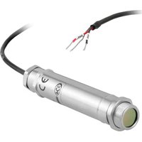
Close-up of a metallic cylindrical connector with a black cable, no visible text or symbolsPCE-IR 50 non-contact infrared sensors measure temperatures from -20°C to 500°C and provide either a linear 4 to 20 mA output, a voltage output or a thermocouple output. This range of output signals is compatible with almost any indicator, controller, recorder, data logger etc., without the need for special interfacing or signal conditioning. They are suitable for most materials such as food, paper, textiles, plastics, leather, tobacco, pharmaceuticals, chemicals, rubber, coal and asphalt; but not materials with a low emissivity, for example polished metals. Two-wire and four-wire versions are available:
Two-wire PCE-IR 50 sensors transmit the target temperature as a 4-20 mA output and offer a simple solution for most applications.
Four-wire PCE-IR 50 sensors transmit the target temperature as a 0-50 mV or thermocouple output (type J or K) plus the internal sensor temperature as a 4-20 mA output. This second output can be used to ensure that the sensor is being operated within the correct ambient temperature limits and prevent damage caused by overheating or overcooling. It can also be used to give an approximate indication of the air temperature surrounding the sensor.
SPECIFICATION
MODEL NUMBERS (X = Output: see Output Table)
| Field of View -20°C to | 100°C 0°C to 250°C 0°C | to 500°C | |
| 2:1 PC21LT-X PC21MT-X PC21HT-X | |||
| 15:1 PC151LT-X PC151MT-X PC151HT-X | |||
| 30:1 PC301LT-X PC301MT-X PC301HT-X | |||
| ø5mm @ 100mm PCCFLT-X PCCFMT-X PCCFHT-X | |||
Output Table
| Model (-X) Target | Temperature Output | Sensor Temperature Output |
| -0 | 4-20 mA (two wire, loop powered) | None |
| -1 | 0-50 mV | 4-20 mA |
| -3 | Type J thermocouple | 4-20 mA |
| -4 | Type K thermocouple | 4-20 mA |
EXAMPLE MODEL NUMBER:
PC151MT-0: PCE-IR 50 infrared temperature sensor with 15:1 optics, temperature range 0°C to 250°C, two-wire 4-20 mA output
GENERAL SPECIFICATIONS
| Accuracy | ±1% of reading or ±1°C whichever is greater |
| Repeatability | ±0.5% of reading or ±0.5°C whichever is greater |
| Emissivity | 0.95 (fixed) |
| Response Time | 240 ms (90% response) |
| Spectral Response | 8 to 14 μm |
| Supply Voltage | 24 V DC (28 V DC max.) |
| Sensor Voltage | 6 V DC min. |
| Maximum Loop Impedance | 900 ohms (4-20 mA output) |
| Output Impedance | 56 ohms (voltage/thermocouple output) |
MECHANICAL SPECIFICATIONS
| Construction | Stainless Steel |
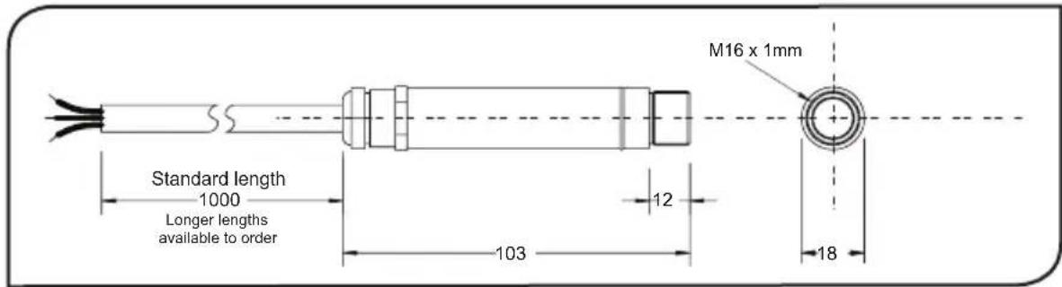
| Dimensions | 18 mm diameter x 103 mm |
| Cable Length | 1 m as standard (up to 30 m available on request) |
| Weight with 1 m Cable | 95 g |
ENVIRONMENTAL SPECIFICATIONS
| Environmental Rating | IP65 |
| Ambient Temperature Range | 0°C to 70°C |
| Relative Humidity | 95% maximum non-condensing |
text_image
M16 x 1mm Standard length 1000 Longer lengths available to order 12 103 18ACCESSORIES
A range of accessories to suit different applications and industrial environments is available. These may be ordered at any time and added on-site. The accessories consist of the following parts.
Fixed mounting bracket Adjustable mounting bracket Air purge collar
Laser sighting tool
OPTIONS
The following options are available. Options are factory installed and must be ordered with the PCE-IR 50.
Air/water cooled housing Certificate of calibration Longer cable (30m max.)
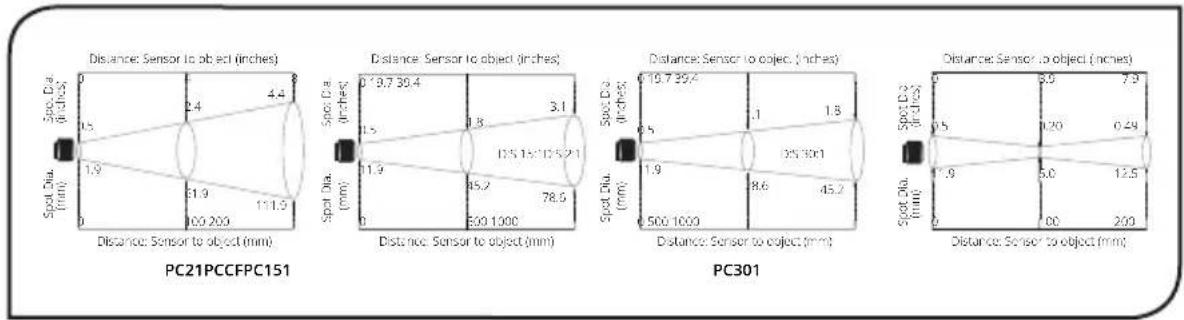
OPTICAL CHART
The optical chart below indicates the nominal target spot diameter at any given distance from the sensing head and assumes 90% energy. Sensors can measure longer distances than shown.
INSTALLATION
The installation process consists of the following stages:
Preparation Mechanical installation Electrical installation
Please read the following sections thoroughly before proceeding with the installation.
PREPARATION
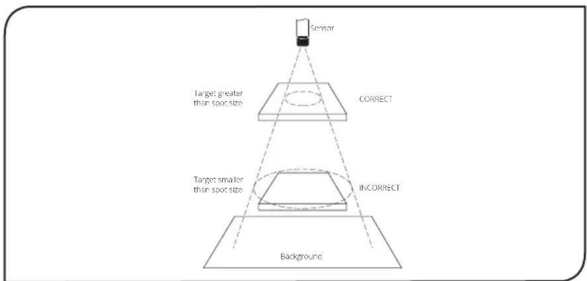
Ensure that the sensor is positioned so that it is focused on the target only.
flowchart
graph TD
    A["Sensor"] --> B["Target greater than spot size"]
    B --> C["CORRECT"]
    C --> D["INCORRECT"]
    D --> E["Background"]
    style A fill:#f9f,stroke:#333
    style E fill:#bbf,stroke:#333
DISTANCE AND SPOT SIZE
The size of the area (spot size) to be measured determines the distance between the sensor and the target. The spot size must not be larger than the target. The sensor should be mounted so that the measured spot size is smaller than the target.
AMBIENT TEMPERATURE
The sensor is designed to operate in ambient temperatures from 0°C to 70°C. For ambient temperatures above 70°C, an air/water-cooled housing will be required.
Avoid thermal shock. Allow 20 minutes for the unit to adjust to large changes in ambient temperature.
ATMOSPHERIC QUALITY
Smoke, fumes or dust can contaminate the lens and cause errors in temperature measurement. In these types of environment the air purge collar should be used to help keep the lens clean.
ELECTRICAL INTERFERENCE
To minimise electromagnetic interference or 'noise', the sensor should be mounted away from motors, generators and such like.
WIRING
Check the distance between the sensor and the indicating/controlling device. If necessary, the PCE-IR 50 sensor can be ordered with a longer cable attached.
MODELS WITH THERMOCOUPLE OUTPUT
When extending the cable, ensure thermocouple extension cable and connectors are used.
POWER SUPPLY
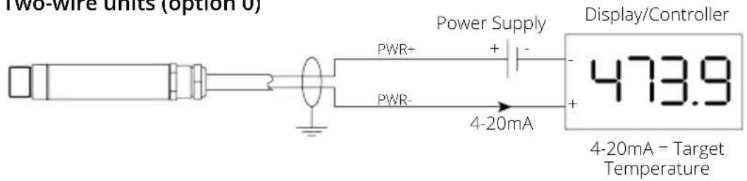
Be sure to use a 24 V DC (25 mA) power supply.
MECHANICAL INSTALLATION
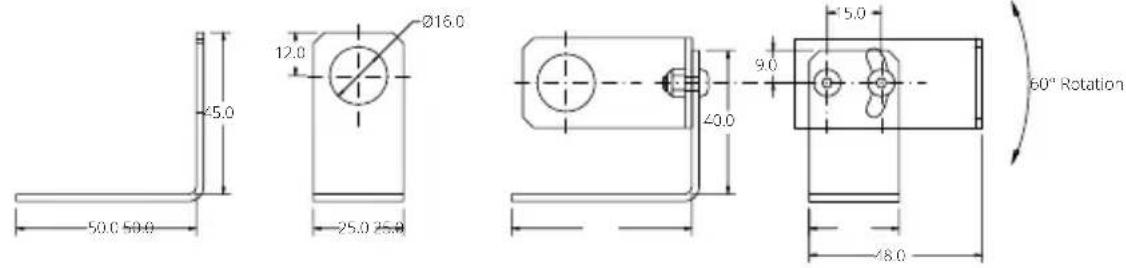
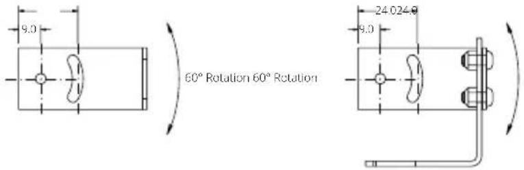
All sensors come with a 1m cable and a mounting nut. The sensor can be mounted on brackets or cut outs of your own design, or you can use the fixed and adjustable mounting bracket accessories which are shown below. Note: The sensor housing must be connected to earth at one point, either the cable shield termination or the sensor housing.
Fixed Mounting Bracket Adjustable Mounting Bracket
text_image
45.0 12.0 Ø16.0 50.0 50.0 25.0 25.0 40.0 9.0 5.0 60° Rotation 8.02 x Mounting Holes M4 Clearance 2 x Mounting Holes M4 Clearance
text_image
9.0 60° Rotation 60° Rotation 24.024.0 9.0AIR/WATER COOLED HOUSING
The air/water cooled housing shown below allows the sensor to withstand high ambient temperatures. It is equipped with two 1/8" BSP fittings. Water temperature should be 10°C to 27°C for efficient cooling. Chilled water below 10°C is not recommended. To avoid condensation, the air purge collar should be used with the water-cooled housing. Water flow rate should be no more than 0.5 to 1.5 litres/min.

text_image
1/8 BSP water/air connections M16 x 1mm 2119 53 103 40.0AIR PURGE COLLAR
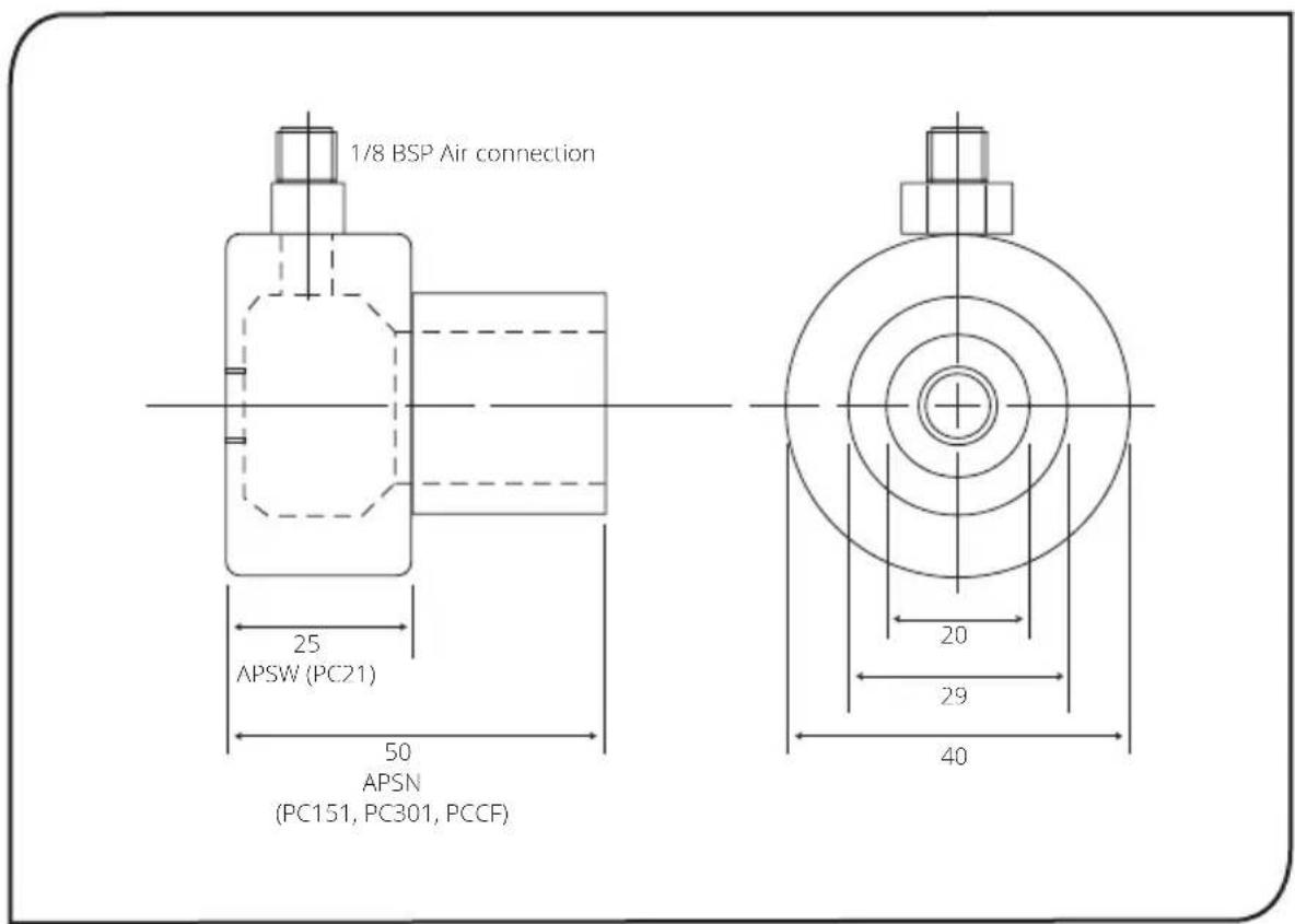
The air purge collar below is used to keep dust, fumes, moisture, and other contaminants away from the lens. It must be screwed in fully. Air flows into the 1/8" BSP fitting and out of the front aperture. Air flow should be no more than 5 to 15 litres/min.
Clean or 'instrument' air is recommended.
text_image
1/8 BSP Air connection 25 APSW (PC21) 50 APSN (PC151, PC301, PCCF) 20 29 40Two-wire units (option 0)
text_image
Two-wire units (option 6) Power Supply PWR+ + - PWR- 4-20mA Display/Controller 473.9 4-20mA - Target Temperature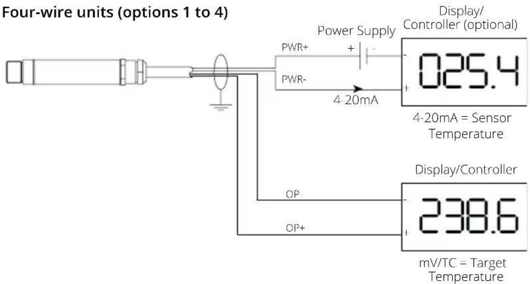
text_image
Four-wire units (options 1 to 4) Power Supply PWR+ + PWR- 4-20mA Display/ Controller (optional) 025.4 4-20mA = Sensor Temperature Display/Controller OP- OP+ 238.6 mV/TC = Target TemperatureOPERATION
Once the sensor is in position and the appropriate power, air, water, and cable connections are secure, the system is ready for continuous operation by completing the following simple steps:
- Turn on the power supply
- Turn on the meter, chart recorder or controller
- Read / monitor the temperature
IMPORTANT
Be aware of the following when using the sensor:
- If the sensor is exposed to significant changes in ambient temperature (hot to cold, or cold to hot), allow 20 minutes for the temperature to stabilise before taking or recording measurements.
- Do not operate the sensor near large electromagnetic fields (e.g. around arc welders or induction heaters).
Electromagnetic interference can cause measurement errors. - Wires must be connected only to the appropriate terminals.
- Do not damage the cable, as this could provide a path for moisture and vapour into the sensor.
- Do not open the sensor housing. This will damage the sensor and invalidate the warranty.
MAINTENANCE
Our customer service representatives are available for application assistance, calibration, repair, and solutions to specific problems. Contact our Service Department before returning any equipment. In many cases, problems can be solved over the telephone. If the sensor is not performing as it should, try to match the symptom below to the problem. If the table does not help, call Calex for further advice.
TROUBLESHOOTING
| Symptom Probable | Cause Solution | |
| No output No power | to sensor Check power supply and wiring | |
| Inaccurate measured temperature | Target too small for sensor's field of view | Ensure the sensor's view is completely filled by the target. Position the sensor closer to the target to measure a smaller area. |
| Target is a reflective metal surface | Measure a non-reflective area, or paint or coat a measurable area of the target to make it non-reflective | |
| Field of view obstruction | Remove obstruction; ensure sensor has a clear view of target | |
| Dust or condensation on lens | Ensure lens is clean and dry. Clean gently with a soft lens cloth and water. If problem recurs, consider using an air purge collar. | |
| Incorrect wire connections | Check wire colour codes | |
| Erroneous temperature (mA or mV outputs) | Output temperature scale mismatch | Re-scale input temperature range on measurement instrument to match sensor |
| Erroneous temperature (thermocouple output) | No Cold Junction Compensation (CJC) or wrong type of extension cable | Enable CJC on measurement instrument; ensure extension cable and connectors are of the correct thermocouple type |
LENS CLEANING
Keep the lens clean at all times. Any foreign matter on the lens would affect measurement accuracy. Blow off loose particles (if not using the air purge accessory) with an air 'puffer'.
GUARANTEE
Calex guarantees each instrument it manufactures to be free from defect in material and workmanship under normal use and service for the period of two years from the date of purchase. This guarantee extends only to the original buyer according to Calex Terms and Conditions of Sale.