CPC 50 - Measuring equipment PCE Instruments - Free user manual and instructions
Find the device manual for free CPC 50 PCE Instruments in PDF.

| Product type | Particle counter |
| Brand | PCE Instruments |
| Model | CPC 50 |
| Dimensions (L x W x H) | 220 x 150 x 50 mm (estimated) |
| Weight | 0.5 kg |
| Power supply | 12 V DC via mains adapter or rechargeable battery |
| Measuring ranges | 0.3 to 10 µm (6 channels) |
| Measurement units | pcs/m³ or pcs/L (selectable) |
| Display | Backlit LCD screen |
| Communication | Modbus RTU (RS485) |
| Sampling flow rate | 2.83 L/min (adjustable) |
| Sensor | Semiconductor laser |
| Data storage | Internal (via Modbus commands) |
| Resolution | 0.1 pcs/m³ |
| Operating temperature | 0 to 50 °C |
| Relative humidity | < 90% RH (non-condensing) |
| Main functions | Real-time particle counting, user coefficient adjustment, output unit setting, scheduled shutdown |
| Maintenance and cleaning | Clean the housing with a soft, dry cloth. Avoid solvents. Keep air vents clear. |
| Safety | Use the supplied power supply. Do not expose to water or extreme temperatures. |
| Spare parts and repairability | Contact PCE Instruments after-sales service for spare parts and repairs. |
| General information | CE compliant. Supplied with user manual and mains adapter. |
Frequently Asked Questions - CPC 50 PCE Instruments
User questions about CPC 50 PCE Instruments
0 question about this device. Answer the ones you know or ask your own.
Ask a new question about this device
Download the instructions for your Measuring equipment in PDF format for free! Find your manual CPC 50 - PCE Instruments and take your electronic device back in hand. On this page are published all the documents necessary for the use of your device. CPC 50 by PCE Instruments.
USER MANUAL CPC 50 PCE Instruments
User Manual Cleanroom Particle Counter PCE-CPC 50
Cleanroom Particle Counter PCE-CPC 50

Applications
● Power battery manufacturing
- Chip manufacturing
● Medical and pharmaceutical
- Precision machining
Description
The PCE-CPC 50 online particle counter adopts the principle of optical scattering, which can accurately detect and calculate the number of suspended particles of different particle sizes in the air per unit volume. It can output the particle count of 6 channels of 0.3 m , 0.5 m , 1.0 m , 2.5 m , 5.0 m and 10 m at the same time (the default unit is pcs / m^3 , can be switched to pcs / L ; pcs / 28.3L ).
Features
● 4 in 1 integrated particle counter of particulate matter sensor, filter, flow sensor and pump
- Output particle number (PCS/m ^3 , PCS/L or PCS/28.3L) in 6 channels including 0.3μm, 0.5μm, 1.0μm, 2.5μm, 5.0μm, 10μm
● Built-in high power industrial grade linear laser, accurate identification
● Built-in pump and flow sensor for constant stable sampling
- Wide working temperature -30°C\~70°C, stable for different clean room application
● With voltage regulator design and EMC compliant, strong anti-static ability
- Modbus RS485,MQTT, 4-20mA output for online remote monitoring
Working Principle
When sampled particles pass through light beam (laser), there will be light scattering phenomenon. Scattered light will be converted into electrical signal (pulse) via photoelectric transformer. The bigger particles will obtain stronger pulse signal (peak value). Through peak value and pulse value quantity concentration of particles in each size can be calculate. Thus, real-time measurement data is obtained through measuring quantity and strength of scattered light.
Cleanroom Particle Counter PCE-CPC 50 Specification
| Operating principle | Light Scattering |
| Detect particle diameter range | >0.3μm, >0.5μm, >1.0μm, >2.5μm, >5.0μm, >10μm |
| Measurement error | <100pcs/l: ±30pcs/L>100pcs/L: ±30% of readingCondition: 0C ~ 40C,50+10%RH(0°C ~ 40°C, 50 ±10%RH. Reference instrument TSI 9306. TSI 930 count efficiency 50% @ 0.3 μm and 100% for particles >0.45 μm) |
| Time to first reliable reading | ≤8s |
| Sampling interval | 1s |
| Working condition | 0°C~45°C; 0~95%RH (non-condensing) |
| Storage condition | -20~60°C, 0~95%RH (non-condensing) |
| Working current | ≤1A |
| Communication | RS485 (standard)RJ45 (standard)4~20mA (standard) |
| Lifetime | ≥3 years |
| Sampling flow rate | 2.83L/min |
| Standard | Comply with JJF 1190-2008 |
- Product dimensions (unit: mm, tolerance: ±2 mm)
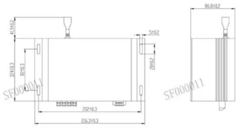
- Pin Definition Diagram
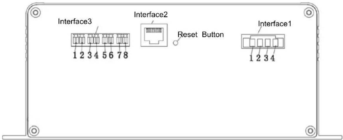
| Interface 1 | No. | PIN | Description | Connector:KF2EDGRM-3.81-6P-14-curved needleinsertion:KF2EDGKM-3.81-6P-14 | |
| 1 | VCC | Power terminal (+12VDC) | |||
| 2 | GND | Power terminal (GND) | |||
| 3 | TB | Communication interface (RS485_TB) | |||
| 4 | TA | Communication interface (RS485_TA) | |||
| Interface 2 | RJ45 | Connector:HR911105A(Fusida) | |||
| 1 | I1 + | I1 Positive pole | >0.5um channel | ||
| 2 | I1 - | I1 Negative pole | |||
| 3 | I2 + | I2 Positive pole | >1.0um channel | ||
| Interface 3 | 4 | I2 - | I2 Negative pole | Connector:KF2EDGRM-3.81-6P-14-curved needleInsertion:KF2EDGKM-3.81-6P-14 | |
| 5 | I3 + | I3 Positive pole | >2.5um channel | ||
| 6 | I3 - | I3 Negative pole | |||
| 7 | I4 + | I4 Positive pole | >5.0um channel | ||
| 8 | I4 - | I4 Negative pole | |||
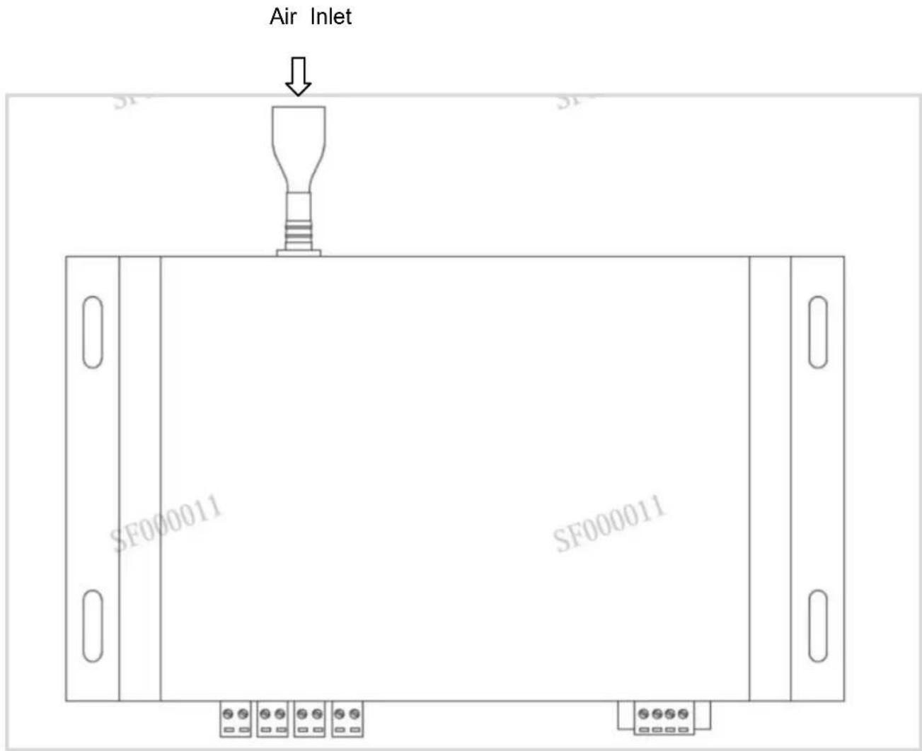
Installation Instruction
When this product is installed and used in the system, the air flow of the air inlet and air outlet should be guaranteed to be smooth; in order to avoid the dust deposition on the surface of the sensitive device during use, which will affect the test accuracy of the sensor, it is recommended to install the sensor in the following way.
Recommended installation method:
Precautions for Use
※ The instrument is forbidden to be used in environments with high dust concentration, environments containing moisture, oil and corrosive substances, and environments with high temperatures exceeding the allowable use.
※ Do not block the air inlet and outlet to avoid damage to the air pump.
※ The product is an integral part, users should not disassemble it to prevent irreversible damage.
※ Do not cause great vibration to the product, so as not to affect the internal air tightness.
※ The device cannot run continuously, which will shorten the service life of the product.
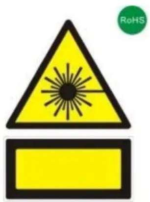
This product contains Class IIIB laser products, which contain laser radiation, avoid direct exposure to the eyes. Do not remove the case or cover. The warning signs are as following:
1 Protocol overview
1.1 Serial RS485 communication protocol
1) The data of this protocol are all hexadecimal data. For example, "46" is [70] in decimal.
2) [xx] is single-byte data (unsigned, 0-255); double-byte data high byte is in front and low byte is behind.
3) Baud rate: 9600b/s; data bits: 8 bits; stop bits: 1 bit; parity bit: none.
2 UART serial communication protocol format
The device adopts the Modbus RTU communication protocol, and the requirements are as follows:
1) The device acts as a slave;
2) The Modbus 03 function code (Read Holding Registers) can be used to read the device status and data; the Modbus 06 function code (Preset Single Register) can be used to set the device status.
3) If the function code in the sent message does not meet the requirements, the device will reply the error code 01 (ILLEGAL FUNCTION) through the 81 function code message; if the request address in the sent message does not meet the requirements, the device will report the 81 function code. The text reply error code 02 (ILLEGAL DATA ADDRESS) notification.
3 Device factory default settings
1) The factory address is 01 by default.
2) The factory default is intermittent working mode. (Work 1 min/ Sleep 4 min)
3) The factory defaults all user coefficients are 1.0000.
4) The factory default setting control flow rate is 2.83 L/min (cannot be changed at will).
4 Check code
CRC-16 (Modbus), high byte first, low byte after.
5 Register address table
Restriction Description
1) Read-only registers and readable and writable registers are not allowed to overlap.
2) Only function of writing a single register is implemented, and writing multiple registers is not available.
3) The total number of registers is limited, currently 32 input registers and 32 holding registers are supported.
4) The current version does not support file transfer with a large amount of data.
5) See Table 1 and Table 2 for register details, all registers are 16-bit word, and the register address is register number-1.
Table 1: Input Registers
| Data No. | Address | Definition | Explanation |
| IR1 | 00H | Version No. (Enlarge 100) | |
| IR2 | 01H | Reserve | |
| IR3 | 02H | Reserve | |
| IR4 | 03H | The number of particles >0.3μm | ≥0.3μm particle quantity high byte |
| IR5 | 04H | The number of particles >0.3μm | ≥0.3μm particle quantity low byte |
| IR6 | 05H | The number of particles >0.5μm | ≥0.5μm particle quantity high byte |
| IR7 | 06H | The number of particles >0.5μm | ≥0.5μm particle quantity low byte |
| IR8 | 07H | The number of particles >1.0μm | ≥1.0μm particle quantity high byte |
| IR9 | 08H | The number of particles >1.0μm | ≥1.0μm particle quantity low byte |
| IR10 | 09H | The number of particles >2.5μm | ≥2.5μm particle quantity low byte |
| IR11 | 0AH | The number of particles >2.5μm | ≥2.5μm particle quantity low byte |
| IR12 | 0BH | The number of particles >5.0μm | ≥5.0μm particle quantity high byte |
| IR13 | 0CH | The number of particles >5.0μm | ≥5.0μm particle quantity low byte |
| IR14 | 0DH | The number of particles >10μm | ≥10μm particle quantity high byte |
| IR15 | 0EH | The number of particles >10μm | ≥10μm particle quantity low byte |
| IR16 | 0FH | Reserve | |
| IR17 | 10H | Reserve | |
| IR18 | 11H | Reserve | |
| IR19 | 12H | Reserve | |
| IR20 | 13H | Reserve | |
| IR21 | 14H | Reserve | |
| IR22 | 15H | Reserve | |
| IR23 | 16H | Reserve | |
| IR24 | 17H | Gas flow value | Actual gas flow value multiplied by 100 |
| IR25 | 18H | Reserve | |
| IR26 | 19H | Reserve | |
| IR27 | 1AH | Reserve | |
| IR28 | 1BH | Reserve | |
| IR29 | 1CH | Reserve | |
| IR30 | 1DH | Reserve | |
| IR31 | 1EH | Reserve | |
| IR32 | 1FH | Reserve |
Table 2: Holding Registers
| Data No. | Address | Definition | Explanation |
| IR1 | 00H | Reserve | |
| IR2 | 01H | Reserve | |
| IR3 | 02H | Address setting register | Slave address (1-247) |
| IR4 | 03H | Reserve | |
| IR5 | 04H | Reserve | |
| IR6 | 05H | Reserve | |
| IR7 | 06H | >0.3μm particles user coefficien | Reserve |
| IR8 | 07H | >0.5μm particles user coefficier | Reserve |
| IR9 | 08H | >1.0μm particles user coefficier | Reserve |
| IR10 | 09H | >2.5μm particles user coefficien | Reserve |
| IR11 | 0AH | >5.0μm particles user coefficien | Reserve |
| IR12 | 0BH | >10μm particles user coefficien | Reserve |
| IR13 | 0CH | Reserve | |
| IR14 | 0DH | Device intermittent stop time | Set the device intermittent stop time (min) |
| IR15 | 0EH | Device control traffic size | Actual set gas flow value multiplied by 100 |
| IR16 | 0FH | Reserve | |
| IR17 | 10H | Reserve | |
| IR18 | 11H | Reserve | |
| IR19 | 12H | Reserve | |
| IR20 | 13H | Output unit | 3 output units: pcs/m3, pcs/L, pcs/28.3L |
| IR21 | 14H | Working mode | 2 working modes: continues measurement, single accumulated count mode |
| IR22 | 15H | Reserve | |
| IR23 | 16H | Reserve | |
| IR24 | 17H | Reserve | |
| IR25 | 18H | Reserve | |
| IR26 | 19H | Reserve | |
| IR27 | 1AH | Reserve | |
| IR28 | 1BH | Reserve | |
| IR29 | 1CH | Reserve | |
| IR30 | 1DH | Reserve | |
| IR31 | 1EH | Reserve | |
| IR32 | 1FH | Reserve |
6 Host communication protocol format Function
code description
The PCE-CPC 50 supports the following function codes:
0x03: read holding register
0x04: read input register
0x06: write a single register
7 Command example
Application conditions
1) Assuming a single sensor.
2) All data are hexadecimal data, and DFX nee to be converted to decimal when calculating data.
3) Symbol description:
① IP is the device address.
② CRC16 is MODBUSCRC16 two-byte check, the high byte is in the front and the low byte is in the back.
③ CS is 0-ADD8 and check, the lowest byte of the previous data and +CS result is 0x00.
④ DF1 DF2 DF3 DF4 represent uncertain data.
7.1 Read >0.3um, >0.5um, >1.0um, >2.5um >5.0um, >10um of particles in each channel
7.7.1 Read >0.3 m particle count:
Send: IP 04 00 03 00 02 CRC16
7.1.3 Read >1.0μm particle count:
Send: IP 04 00 07 00 02 CRC16
7.1.4 Read >2.5μm particle count:
Send: IP 04 00 09 00 02 CRC16
7.2 Read real-time gas flow value
Send: IP 04 00 17 00 01 CRC16
Description: Real-time gas flow value = (DF1*256+DF2)/100 (L/min)
7.3 Continuously read input register data
Send: IP 04 00 03 00 15 CRC16
Real-time gas flow value = (DF41*256+DF42)/100 (L/min)
7.4 Read >0.3um, >0.5um, >1.0um, >2.5um >5.0um, >10um of particles user coefficient in each channel
7.4.1 Read >0.3μm particle count
Send: IP 03 00 06 00 01 CRC16
Description: >1.0 μm particles user coefficient= (DF1*256+DF2)/10000
7.4.4 Read >2.5μm particle count
Send: IP 03 00 09 00 01 CRC16
Description: >1.0 μm particles user coefficient= (DF1*256+DF2)/10000
7.5 Read output unit
Send: IP 03 00 13 00 01 CRC16
Description: output particles number unit, when DF=0, output unit is pcs/L; when DF=1, output unit is pcs/m ^3 ; when DF=2, output unit is pcs/28.3L.
7.6 Read working mode
Send: IP 03 00 14 00 01 CRC16
Description: DF1=0 is continuous measurement mode, and real-time measurement values will be continuously output. DF1 = 1 is the single cumulative counting mode. When the output unit is pcs/L, the detection value will be output after 21 seconds of reading; when the output unit is pcs/m ^3 , the output detection value of 5 minutes
can be read; when the output unit is pcs/28.3L, the output detection value of 60 seconds will be read. When working mode is set, the parameter is not saved after power off. After the device is powered on again, the default working mode is restored: Continuous measurement mode. In the single cumulative counting mode, the device carries out a fixed time measurement, and the output value of the device does not change after the single reading. If you need to measure again, you need to send the set working mode command again, or switch to continuous measurement mode
7.7 Confirm device address
Send: IP 03 00 02 00 01 CRC16
7.8 Read the intermittent operation stop time of the device
Send: IP 03 00 0D 00 01 CRC16
7.9 Read device setting flow size
Send: IP 03 00 0E 00 01 CRC16
7.10 Continuously read input register data
Send: IP 03 00 02 00 0D CRC16
7.11 Modify >0.3μm, >0.5μm, >1.0μm, >2.5μm, >5.0μmm, >10μm of particles user coefficient in each channel
7.11.1 Modify >0.3μm of particles user coefficient in each channel
Description: >0.3μm particle quantity user coefficient =(DF1*256+DF2)/10000
7.11.2 Modify >0.5μm of particles user coefficient in each channel
7.11.3 Modify >1.0μm of particles user coefficient in each channel
Description: >1.0μm particle quantity user coefficient = (DF1*256+DF2)/10000
7.11.4 Modify >2.5μm of particles user coefficient in each channel
Description: >2.5μm particle quantity user coefficient =(DF1*256+DF2)/10000
7.11.5 Modify >5.0μm of particles user coefficient in each channel
Description: >5.0μm particle quantity user coefficient =(DF1*256+DF2)/10000
7.11.6 Modify >10μm of particles user coefficient in each channel
Description: >10μm particle quantity user coefficient =(DF1*256+DF2)/10000
7.12 Modify the device address (the address range that can be set is 1-254)
Send: IP 06 00 02 00 DF1 CRC16 (IP address indicates the device address before the change)
Answer: IP 06 00 02 00 DF1 CRC16 (IP address indicates the new device address)
Description: DF1 indicates the device address to be changed
7.13 Modify the operating stop time of the equipment (the time range that can be set is 1-10000)
7.14 Modify the flow rate set by the control device (the flow rate can be set in the range of 2.0L/min
3.5L/min)
2(pcs/28.3L); set output unit is restored after power off.
7.16 Set working mode
Description: The modified working mode=(DF1*256+DF2), support 0 (continues measurement), 1 (single cumulative counting mode); set output unit is not saved after power off. When working mode is set, the
parameter is not saved after power off. After the device is powered on again, the default working mode is restored: Continuous measurement mode. In the single cumulative counting mode, the device carries out a fixed time measurement, and the output value of the device does not change after the single reading. If you need to measure again, you need to send the set working mode command again, or switch to continuous measurement mode
7.17 Query device address
Send: 11 02 55 FF CS
Description: In the running mode, the query device address is DF1
7.18 Query the software version number
Send: 11 01 1E CS
Description: The version number is DF1-DF13, the ASCII string is the software version number
7.19 Set 4 channel range of 4-20mA
When DF1=0, current modified channel is PM0.5, corresponding measurement range of
4\~20mA=DF2*256*256*256+DF3*256*256+DF4*256+DF5
When DF1=1, current modified channel is PM1.0, corresponding measurement range of
4\~20mA=DF2*256*256*256+DF3*256*256+DF4*256+DF5
When DF1=2, current modified channel is PM2.5, corresponding measurement range of
4\~20mA=DF2*256*256*256+DF3*256*256+DF4*256+DF5
When DF1=3, current modified channel is PM5.0, corresponding measurement range of
4\~20mA=DF2*256*256*256+DF3*256*256+DF4*256+DF5
The range will automatically update the corresponding range according to the set unit. Therefore, it is recommended to confirm (query) the current output unit before setting the measurement range. After the range setting will be saved.
The default output unit is pcs/L, 4\~20mA corresponding default output unit measurement ranges are:
PM0.5->35000000pcs/L, PM1.0->8000000pcs/L, PM2.5->3000000pcs/L, PM5.0->300000pcs/L
7.20 Query MQTT server IP and port number
Send: 11 01 67 CS
Description: MQTT server IP and port number format: [IP1]:[IP2]:[IP3]:[IP4]:[PORT]
IP1=DF1, IP2=DF2, IP3=DF3, IP4=DF4, PORT=DF5*256+DF6
7.21 Modify MQTT server IP and port number
Description: MQTT server IP and port number format: [IP1]:[IP2]:[IP3]:[IP4]:[PORT]
IP1=DF1, IP2=DF2, IP3=DF3, IP4=DF4, PORT=DF5*256+DF6
1 Protocol overview
- This device support DHCP protocol, can obtain the IP address automatically.
● Support the MQTT protocol version: MQTT V3.1.1. - Using JSON data format.
● Support device calibration instructions. - Default IP address and port number connected to the MQTT server: 39.108.78.19:1883 (which can be modified using RS485)
2 Topic List
| Directions | Topic | Description |
| Server->MCU | /productID/deviceID/function/invoke | Server sen the instant command (CMD-1~CMD-10) |
| MCU->Server | /productID/deviceID/function/invoke/reply | Reply to the server 's sending command (ACK) : notifies the server of the received numberAccording to (CMD-999) |
| MCU->Server | /productID/deviceID/properties/report | Device periodically reports data, cycle is intermittent operation cycle (configurable) (CMD-168)Repones to data sent by the server (CMD-101 ~ CMD-110) |
3 Authentication Definition
Product ID: PCE-CPC 50
deviceID: Device factory sn
secureId: sifangguangdian
secureKey: 123456
var clientId = deviceID(device SN)
var username = secureId+"|"+deviceID; // Concatenate user password
var password = md5(username+"|" + secureKey); // Use md5 to generate the abstract
4 Rule of Message
4.1 Messages are delivered in a uniform format where the inputs object is the content of the message.
All send instruction contents will be in inputs.
| Key value | Types | Description |
| cmd | String | Command number |
| inputs | Object | Downlink message content |
| desired | Object | Uplink message content |
| messageId | Otring | Message Id |
Note: All descending instructions must contain the "messageId" and "inputs" fields; and the "inputs" field must begin with cmd field. messageId of the uplink ACK = messageId of the downlink ACK
4.2 Command List
MCU->Server (Downlink)
| Command | Description |
| CMD-1 | Read particle count |
| CMD-2 | Read the real-time gas flow value |
| CMD-3 | / |
| CMD-4 | Read the particle quantity coefficient |
| CMD-5 | / |
| CMD-6 | Read the intermittent operation & stop time of the device |
| CMD-7 | Query the SN code and firmware version |
| CMD-8 | Modify device parameters |
MCU->Server (Uplink)
| Command | Description |
| CMD-101 | Upload the particle count |
| CMD-102 | Upload Real-time gas flow value |
| CMD-103 | / |
| CMD-104 | Upload the particle quantity coefficient |
| CMD-105 | / |
| CMD-106 | Upload the intermittent operation stop time of the device |
| CMD-107 | Upload SN code and firmware version |
| CMD-108 | Modify the device parameter response |
| CMD-168 | Periodically report the data automatically |
| CMD-999 | Uplink ACK(Acknowledgement message of receiving the instruction, which informs the server that the instruction was received) |
5 Instruction specification
5.1 Read particle count CMD-1
Description: Read >0.3um, >0.5um, >1.0um, >2.5um, >5.0um, >10um of particles count in each channel
Downlink command:
| Parameter | Type | Description |
| - | - | - |
Example:
topic : /prodcutID/deviceID/function/invoke {
"messageId":"1574326733176995841",
"deviceId": "173072083110001",
"timestamp":1664183717422,
"functionId":"CMD1",
"messageType": "INVOKE_FUNCTION",
"inputs":[{"cmd":"CMD-1"}]}
Uplink ACK (Acknowledgement message of receiving the instruction, which informs the server that the instruction was received):
TOPIC: /prodcutID/deviceID/function/invoke/reply
{
    "messageId":"1574326733176995841",
    "cmd": "CMD-999",
    "output":"success"
}
Uplink data
| Parameter | Type | Description |
| particles_0.3um | Number | >0.3 m particle count |
| particles_0.5um | Number | >0.5 m particle count |
| particles_1.0um | Number | >1.0 m particle count |
| particles_2.5um | Number | >2.5 m particle count |
| particles_5.0um | Number | >5.0 m particle count |
| particles_10um | Number | >10 m particle count |
| Unit | String | Unit (pcs/m ^3 by default) |
topic : /prodcutID/deviceID/properties/report
{
    "cmd": "CMD-101",
    "desired": {
    "particles_0.3um" : 123,
    "particles_0.5um" : 123,
    "particles_1.0um" : 123,
    "particles_2.5um" : 123,
    "particles_5.0um" : 123,
    "particles_10um" : 123,
    "unit":"pcs/m³"
    }
}
5.2 Read the real-time gas flow value CMD-2
Description: Read the real-time gas flow value, Unit is (L/min)
Downlink command:
| Parameter | Type | Description |
| - | - | - |
topic : /prodcutID/deviceID/function/invoke
{
    "messageId":"1574326733176995841",
    "deviceId":"173072083110001",
    "timestamp":1664183717422,
    "functionId":"CMD2",
    "messageType":"INVOKE_FUNCTION",
    "inputs":[{"cmd":"CMD-2"}]
}
Uplink ACK (Acknowledgement message of receiving instruction was received):
TOPIC: /prodcutID/deviceID/function/invoke/reply
{
    "messageId":"1574326733176995841",
    "cmd": "CMD-999",
    "output":"success"
}
Uplink data
| Parameter | Type | Description |
| gas_flow | Number(Floating-point value) | real-time gas flow value |
| unit | String | real-time gas flow (Unit: L/min) |
topic : /prodcutID/deviceID/properties/report {
"cmd":"CMD-102", "desired": { "gas_flow": 2.83 "unit": "L/min" }
5.3 Read the particle quantity coefficient CMD-4
Description: Read the particle quantity coefficient
Downlink command:
| Parameter | Type | Description |
| - | - | - |
topic : /prodcutID/deviceID/function/invoke
{
    "messageId":"1574326733176995841",
    "deviceId":"173072083110001",
    "timestamp":1664183717422,
    "functionId":"CMD4",
    "messageType":"INVOKE_FUNCTION",
    "inputs":[{"cmd":"CMD-4"}]
}
Uplink ACK (Acknowledgement message of receiving the instruction, which informs the server that the instruction was received):
TOPIC: /prodcutID/deviceID/function/invoke/reply
{
    "messageId":"1574326733176995841",
    "cmd":"CMD-999",
    "output":"success"
}
Uplink data:
| Parameter | Type | Description |
| particles_coef_0.3um | Number-integer number | >0.3μm particle count user coefficient,10000 times large |
| particles_coef_0.5um | Number- integer number | >0.5μm particle count user coefficient,10000 times large |
| particles_coef_1.0um | Number- integer number | >1.0μm particle count user coefficient,10000 times large |
| particles_coef_2.5um | Number- integer number | >2.5μm particle count user coefficient,10000 times large |
| particles_coef_5.0um | Number- integer number | >5.0μm particle count user coefficient,10000 times large |
| particles_coef_10um | Number- integer number | >10μm particle count user coefficient,10000 times large |
topic : /prodcutID/deviceID/properties/report
{
    " cmd": "CMD-104",
    "desired": {
    "particles_coef_0.3um" : 123,
    "particles_coef_0.5um" : 123,
    "particles_coef_1.0um" : 123,
    "particles_coef_2.5um" : 123,
    "particles_coef_5.0um" : 123,
    "particles_coef_10um" : 123
    }
}
5.4 Read the intermittent operation stop time of the device CMD-6
Description: Read the intermittent operation stop time of the device
Downlink command:
| Parameter | Type | Description |
| - | - | - |
topic : /prodcutID/deviceID/function/invoke
{
"messageId":"1574326733176995841",
"deviceId":"173072083110001",
"timestamp":1664183717422,
"functionId":"CMD6",
"messageType":"INVOKE_FUNCTION",
"inputs":[{"cmd":"CMD-6"}]
}
Uplink ACK (Acknowledgement message of receiving the instruction, which informs the server that the instruction was received):
TOPIC: /prodcutID/deviceID/function/invoke/reply
{
"messageId":"1574326733176995841",
"cmd":"CMD-999",
"output":"success"
} Uplink data:
| Parameter | Type | Description |
| work_stop_time | Number-Shaping number | Available to set, unit is minute.Cannot set it to be 0, otherwise the setting value is inv |
| Work_run_time | Number- Shaping number | The value is set to 1min.Actively upload MQTT data once the run time is over |
topic : /prodcutID/deviceID/properties/report
{
    "cmd": "CMD-106",
    "desired":{
    "work_stop_time": 10,
    "work_run_time": 1
    }
}
5.5 Query the SN code and firmware version CMD-7
Description: Query the SN code and firmware version Downlink command:
| Parameter | Type | Description |
| - | - | - |
topic : /prodcutID/deviceID/function/invoke
{
    "messageId":"1574326733176995841",
    "deviceId":"173072083110001",
    "timestamp":1664183717422,
    "functionId":"CMD7",
    "messageType":"INVOKE_FUNCTION",
    "inputs":[{"cmd":"CMD-7"}]
}
Uplink ACK (Acknowledgement message of receiving the instruction, which informs the server that the instruction was received):
TOPIC: /prodcutID/deviceID/function/invoke/reply
{
    "messageId":"1574326733176995841",
    "cmd":"CMD-999",
    "output":"success"
}
Uplink data:
| Parameter | Type | Description |
| sn | String | Device sn |
| sw_version | String | sw version |
topic : /prodcutID/deviceID/properties/report
{
"cmd": "CMD-107",
"desired":{
"sn": "123456789",
"sw_version": "xxx"
}
5.6 Modify device parameters CMD-8
Description: Modify device parameters
Downlink command:
| Parameter | Type | Description |
| particles_coef_0.3um | Number | >0.3μm particle count user coefficient, range 1000~65000,10000 time larger, actual coefficient is 0.1~6.5 |
| particles_coef_0.5um | Number | >0.5μm particle count user coefficient, range 1000~65000,10000 time larger, actual coefficient is 0.1~6.5 |
| particles_coef_1.0um | Number | >1.0μm particle count user coefficient, range 1000~65000,10000 time larger, actual coefficient is 0.1~6.5 |
| particles_coef_2.5um | Number | >2.5μm particle count user coefficient, range 1000~65000,10000 time larger, actual coefficient is 0.1~6.5 |
| particles_coef_5.0um | Number | >5.0μm particle count user coefficient, range 1000~65000,10000 time larger, actual coefficient is 0.1~6.5 |
| particles_coef_10um | Number | >10μm particle count user coefficient, range 1000~65000,10000 time larger, actual coefficient is 0.1~6.5 |
| work stop time | Number | Device stop time ,unit is min. |
topic : /prodcutID/deviceID/function/invoke
{
    "messageId":"1574326733176995841",
    "deviceId":"173072083110001",
    "timestamp":1664183717422,
    "functionId":"CMD8",
    "messageType":"INVOKE_FUNCTION",
    "inputs":[
    {"cmd":"CMD-8"},
    {"particles_coef_1.0um":12345},
    {"work_stop_time": 2}
    ]
    }
Uplink ACK (Acknowledgement message of receiving the instruction, which informs the server that the instruction was received):
TOPIC: /prodcutID/deviceID/function/invoke/reply
{
    "messageId":"1574326733176995841",
    "cmd":"CMD-999",
    "output":"success"
}
Uplink data:
| Parameter | Type | Description |
| result | String | success or failed |
topic : /prodcutID/deviceID/properties/report
{
"sn": "123456789",
"cmd": "CMD-108",
"desired":{
"result": "success"
}
}
5.7 Automatically report the data periodically CMD-168
The device will automatically report data periodically without the server sending request data packets. The automatic report period is the intermittent operation period (set by CMD-8). After one working period is complete, the automatic report is uploaded once
Uplink data list:
| Parameter | Type | Description |
| particles_0.3um | Number | >0.3 m particle count |
| particles_0.5um | Number | >0.5 m particle count |
| particles_1.0um | Number | >1.0 m particle count |
| particles_2.5um | Number | >2.5 m particle count |
| particles_5.0um | Number | >5.0 m particle count |
| particles_10um | Number | >10 m particle count |
| Unit | String | Unit ( pcs/m^3 , default) |
topic : /prodcutID/deviceID/properties/report
{
    "cmd": "CMD-168",
    "desired": {
    "particles_0.3um": 123,
    "particles_0.5um": 123,
    "particles_1.0um": 123,
    "particles_2.5um": 123,
    "particles_5.0um": 123,
    "particles_10um": 123,
    "unit": "pcs/m3",
    }
}
Contact
If you have any questions, suggestions or technical problems, please do not hesitate to contact us. You will find the relevant contact information at the end of this user manual.
Disposal
For the disposal of batteries in the EU, the 2006/66/EC directive of the European Parliament applies. Due to the contained pollutants, batteries must not be disposed of as household waste. They must be given to collection points designed for that purpose.
In order to comply with the EU directive 2012/19/EU we take our devices back. We either re-use them or give them to a recycling company which disposes of the devices in line with law.
For countries outside the EU, batteries and devices should be disposed of in accordance with your local waste regulations.
If you have any questions, please contact PCE Instruments.


PCE Instruments contact information
Germany
Chester Rd, Old Trafford Manchester M32 0RS
United Kingdom
Tel: +44 (0) 161 464902 0
Fax: +44 (0) 161 464902 9
info@pce-instruments.co.uk
www.pce-instruments.com/english
The Netherlands
PCE Brookhuis B.V. Institutenweg 15
7521 PH Enschede
Nederland
Telefoon: +31 (0)53 737 01 92
info@pcebenelux.nl
www.pce-instruments.com/dutch
France
PCE Instruments France EURL
United States of America
PCE Americas Inc.
1201 Jupiter Park Drive, Suite 8
Jupiter / Palm Beach
33458 FL
USA
Tel: +1 (561) 320-9162
Fax: +1 (561) 320-9176
info@pce-americas.com
www.pce-instruments.com/us
Spain
PCE Ibérica S.L.
Calle Mula, 8
Pehlivan Sok. No.6/C
www.pce-instruments.com/turkish
Denmark
PCE Instruments Denmark ApS
Birk Centerpark 40
7400 Herning
Denmark