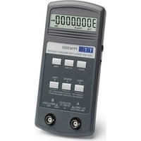
PFM3000 - Measuring equipment Aim TTi - Free user manual and instructions
Find the device manual for free PFM3000 Aim TTi in PDF.


| Product type | Digital frequency counter |
| Brand | Aim TTi |
| Model | PFM3000 |
| Frequency measurement ranges (input A) | 3 Hz to 125 MHz |
| Frequency measurement ranges (input B) | 80 MHz to 3000 MHz |
| Functions | Frequency A, Frequency B, Period A |
| Selectable measurement times | 0.3 s, 1 s, 10 s |
| Input impedance A | 1 MΩ // 20 pF |
| Input impedance B | 50 Ω |
| Base accuracy | ±2 ppm (after warm-up at 23°C) |
| Temperature stability | ±0.3 ppm/°C (18°C to 28°C) |
| Annual aging | Up to ±5 ppm first year |
| Power supply | Internal battery (type not specified) |
| Display | LCD with indicator lights |
| Input protection | Up to 250 V rms (accidental, 50/60 Hz) |
| Safety | Class III per IEC, compliant with EN61010-1 |
| Auto power off | After 15 seconds of inactivity (battery saving) |
| Hold function | Freezes the display |
| Low-pass filter (input A) | Cutoff frequency 50 kHz |
| Calibration | Via CAL hole on rear panel (adjustable capacitor) |
| Cleaning | Slightly damp cloth (water or mild detergent) |
| Operating temperature | 5°C to 40°C, humidity 20% to 80% (non-condensing) |
Frequently Asked Questions - PFM3000 Aim TTi
User questions about PFM3000 Aim TTi
0 question about this device. Answer the ones you know or ask your own.
Ask a new question about this device
Download the instructions for your Measuring equipment in PDF format for free! Find your manual PFM3000 - Aim TTi and take your electronic device back in hand. On this page are published all the documents necessary for the use of your device. PFM3000 by Aim TTi.
USER MANUAL PFM3000 Aim TTi
THURLBY THANDAR INSTRUMENTS
PFM3000
Portable Frequency Meter
INSTRUCTION MANUAL
Table of Contents
Introduction 1
Specification 2
Safety 4
Operation 5
Calibration and Maintenance 6
Securite 7
Fonctionnement 8
The PFM3000 is a portable frequency meter with a large 11.5mm 81/2 -digit liquid crystal display (LCD). The frequency range is 3Hz to 3GHz and measurement capabilities include frequency and period with push-to-measure and auto power-down functions.
A hold function is available which allows any reading to be frozen and displayed indefinitely.
Input A is a high impedance input (1MΩ) or frequencies in the range 3Hz to 125MHz. Input B is a nominal 50Ω input for frequencies in the range 80MHz to 3GHz.
The instrument uses a reciprocal counting technique to provide high resolution at all frequencies. At least 7 significant digits of answer are produced per second of measurement time.
A low pass filter can be selected to ensure stable readings at low frequencies.
Indicators show measurement function, measurement time, low battery and the units of the answer which may be Hz, kHz, MHz, ns, us, ms or s.
The low power design gives typically 20 hours battery life from a 9 volt alkaline cell. Use of the power saving push-to-measure functions will avoid wasting battery life by automatically switching the unit off after a short time.
The instrument has a robust ABS case.
Specification
MEASUREMENT FUNCTIONS
Frequency (Range A)
Frequency Range: 3Hz to >125MHz
Resolution: 10 -7Hz to 100Hz (see below)
Frequency (Range B)
Frequency Range: 80MHz to >3000MHz
Resolution: 1Hz to 10kHz (see below)
Period (Range A only)
Period Range: 8ns to 330ms
Resolution: 10 -7ns to 1us (see below)
Measurement time
Selectable as 10s, 1s or 0.3s.
Resolution
The displayed resolution depends upon the measurement time and the input frequency. Eight or nine digits are displayed for a 10 second measurement time. Six, seven or eight digits are displayed for the shorter measurement times depending on input frequency. Usable resolution can be further reduced by noise, especially at low frequencies.
Accuracy
Measurement accuracy is the sum of timebase accuracy and measurement resolution plus one count.
TIMEBASE
Crystal Oscillator Frequency:
10MHz
Initial Oscillator Adjustment Error: ± 2ppm (closed-case adjustment by user)
Oscillator Temperature Coefficient: Typically less than
± 0.3ppm / °C18°C to 28°C,
± 10ppm - 20°C to 70°C
Oscillator Ageing Rate: <± 5ppm/year
OPERATING FUNCTIONS
Press to measure
With the power switch off, pressing any of the function select keys will power the instrument up in the corresponding function. The instrument will automatically switch off 15 seconds after the last key-press.
Hold
Pressing the Hold key will stop further measurements being made and the current measured value will remain in the display, with the Hold indicator on, until the Hold key is pressed again.
Noise filter
The Filter key controls a low pass filter, with a cut-off frequency of about 50kHz , to ensure stable readings at low frequencies.
Signal activity indicator
When no input signal is detected the Trig indicator will be off, indicating that no measurement is possible. The gate time indicator flashes until the first measurement interval is complete.
INPUT SPECIFICATIONS
Input A
Input Impedance: 1MΩ//20pF (AC coupled)
Frequency Range: <3Hz to >125MHz
Sensitivity: Sinewave - 15mVrms 10Hz to 125MHz
Input B
Input Impedance: 50Ω nominal (AC coupled)
Frequency Range: <80MHz to >3GHz
Sensitivity: Sinewave - 12mVrms 80MHz to 2GHz, 25mVrms to 2.5GHz, 50mVrms to 3GHz
Maximum Input Voltage
Input A and Input B:

30Vdc; 30V rms 50/60Hz with respect to ground 1/一 reducing to 1Vrms above 1MHz
Note that the inputs will not be damaged if subjected to an accidental short-term connection to a 50/60Hz line voltage not exceeding 250V rms.
POWER REQUIREMENTS
Battery Type: 9V PP3 alkaline
Battery Life: Typically 20 hours
Low Battery Indicator: 'Bat' shows in display when approximately 10% of battery life remains.
GENERAL
Display: 8½ digit LCD, 11.5mm high (0.45"); 15 annunciators show measurement units, input, mode and time.
Operating Range: +5°C to +40°C , 20% to 80% RH
Storage Range: -20°C to +60°C
Environmental: Indoor use at altitudes up to 2000m Pollution Degree 2
Size: 81mm x 178mm x 30mm (WxLxD)
Weight: 190gms excluding battery
Safety & EMC: Complies with EN61010-1 & EN61326-1. For details, request the EU Declaration of Conformity for this instrument via http://www.aimtti.com/support (serial no. needed).
Safety
This instrument is Safety Class III according to IEC classification and has been designed to meet the requirements of EN61010-1 (Safety Requirements for Electrical Equipment for Measurement, Control and Laboratory Use). This instrument has been tested in accordance with EN61010-1 and has been supplied in a safe condition. This instruction manual contains some information and warnings which have to be followed by the user to ensure safe operation and to retain the instrument in a safe condition. This instrument has been designed for indoor use in a Pollution Degree 2 environment in the temperature range 5°C to 40°C , 20% -80% RH (non-condensing). It may occasionally be subjected to temperatures between +5°C and -10°C without degradation of its safety. Do not operate while condensation is present. Use of this instrument in a manner not specified by these instructions may impair the safety protection provided. Do not operate the instrument outside its rated supply voltages or environmental range.
WARNING! All accessible parts will be at the same voltage potential as the outer of the BNC input sockets: to maintain user safety it is therefore essential that neither input is connected to a voltage above 30Vdc or 30Vrms with respect to ground 1/2 . Note that although the inputs will withstand accidental connection to an AC line voltage up to 250V rms, 50/60Hz, users will be at risk if the instrument 'ground' is connected to such hazardous voltages. The apparatus shall be disconnected from all voltage sources before it is opened for any adjustment, replacement, maintenance or repair, including replacement of the battery.
Any adjustment, maintenance and repair of the opened instrument under voltage shall be avoided as far as possible and, if inevitable, shall be carried out only by a skilled person who is aware of the hazard involved.
Do not wet the instrument when cleaning it. The following symbol is used on the instrument and in this manual:

meaning CAUTION. Damage to the instrument may occur if these precautions are ignored.
Operation
Power
To fit or replace the battery, undo the battery cover screw and lift off the cover. Fit the battery snap, observing the correct polarity, insert the battery into the compartment and replace the cover. WARNING! To prevent shock hazard, all inputs must be removed before changing the battery.
Turn the instrument on by sliding the power switch on the left-hand side of the instrument to ON. With no signal connected the display should show 0.0, the Function annunciator (default FREQ A), and the selected measurement time annunciator flashing (default 0.3s).
Function and Measurement Time Selection
Pushing any of the keys, FREQ A, FREQ B or PERIOD A, will set the instrument to the respective function and the selected function will be shown by annihilators in the LCD. Select the measurement function appropriate to the signal to be measured and connect the signal to the corresponding BNC input; the TRIG annihilator should show in the display to indicate that the signal has been detected. Measurement time is selected by pressing the TIME key, the selected time being shown by the appropriate annihilator in the LCD. Switching between FREQ A and PERIOD A will immediately convert the present measurement; otherwise a change of function or measurement time will initiate a new measurement. This may also be accomplished without a change of function or measurement time by pressing the key corresponding to the function currently selected; the new measurement will start immediately.
When a measurement is started, the measurement time annunciator flashes until a true result for that selected measurement time is displayed, at which point the annunciator stays on. Further display updates then show the running average of the signal behaviour over the last 0.3s (1 update), 1s (2 updates per second) or 10s (1 update per second) depending on the selected measurement time. Note that if a 1s or 10s measurement time is selected, starting or restarting the measurement gives a true result with at least 6 digits after 0.3s, followed by at least 7-digits after 1s and, finally, at least 8-digits after 10s (if 10s measurement is selected).
The frequency and period measurement functions both produce at least 7 digits of answer per second of measurement time and the units and decimal points are adjusted automatically to give the answer in the most convenient units. Pressing the HOLD key will stop the measurement and freeze the display with the 'Hold' annunciator showing in the LCD. Hold may be cancelled by a second press of the HOLD key. With the power switch in the off position pressing one of the function keys will power the instrument on and set the selected function. The instrument will then function normally and respond to all key presses.
After a period of about 15 seconds with no key presses the instrument will automatically power down to conserve the battery. Switching the ON/OFF switch ON then OFF during these 15 seconds will have no effect.
Inputs
Socket A is used for frequencies in the range 3Hz to 125MHz. Input impedance is 1MΩ in parallel with 20pF. Care should be taken when measuring input signals above 350mV rms (the onset of diode clipping) with poor signal to noise ratios as under these circumstances it is possible for noise to generate spurious counts. To ensure a correct count, therefore, noisy signals should be attenuated externally before being presented to the counter. A convenient attenuation factor of 10 can be achieved by the use of a x10 oscilloscope probe. The A socket will accept most types of waveform – including sine, square and pulse signals. With pulse waveforms the mark to space ratio should not exceed 90% and the minimum pulse width should be greater than 3ns. A low pass filter with a cut-off frequency of 50kHz may be selected by pressing the FILTER key. The message FILT ON shows briefly in the display and the Filt annunciator is turned on; pressing FILTER a second time turns the filter off (display briefly shows FILT OFF and the Filt annunciator goes off). Use the filter with low frequency large amplitude signals.
Socket B is used for frequency measurements in the range of 80MHz to 3000MHz. The input impedance is nominally 50Ω . The signal is diode clipped with inputs over 350mV rms. Ideally, the signal being measured should have a 50Ω source impedance to avoid standing waves which could give spurious results. The input cable should be kept as short as possible and 50Ω coaxial cable should be used.
Both inputs are protected against accidental connection of mains voltage up to 250V rms at 50 / 60Hz . Note that the instrument is not intended for the continuous measurement of the mains supply because the occasional high voltage transients which occur on mains supplies could damage the input. The maximum input voltage at frequencies above 1MHz is 1V rms.
Note that because of its high sensitivity the instrument may give a spurious reading when nothing is connected to its input. This does not affect normal operation and should be ignored.
Note also that the signals mixed with other components which fall within the frequency and sensitivity range of the input being used can cause incorrect counting; externally attenuating the signal before presenting it to the counter may help to obtain a correct reading. Signals with slow edge speeds (such as low frequency sinewaves) will show some jitter on the reading because of random noise.
TIMEBASE & OTHER ACCURACY CONSIDERATIONS
The instrument has an internal oscillator of good stability but nevertheless the operating frequency is affected by temperature and time (ageing). The oscillator has been factory set such that it is within ± 2ppm (parts per million) after warm-up in an ambient of 23°C . At ambient temperatures other than 23°C the additional error should be less than ± 0.3ppm / °C for the operating range 18°C to 28°C . The crystals are pre-aged before assembly but a further ageing of up to ± 5ppm can occur in the first year. Since the ageing rate decreases exponentially with time it is an advantage to recalibrate the instrument after the first 6 months use, see Calibration and Maintenance section.
Calibration and Maintenance
Recalibration may be carried out without dismantling the instrument by accessing the trimmer through the hole marked CAL on the back of the case. Use a frequency standard or standard frequency receiver to provide a high accuracy signal at the input and adjust the trimmer slowly for the correct reading.
Cleaning
If the instruments require cleaning use a cloth that is only lightly dampened with water or a mild detergent.
WARNING! TO AVOID DAMAGE TO THE CASE OR DISPLAY WINDOW NEVER CLEAN WITH SOLVENTS.
Securite
Glebe Road • Huntingdon • Cambridgeshire • PE29 7DR • England (United Kingdom)
Telephone: +44 (0)1480 412451 Fax: +44 (0)1480 450409
International web site: www.aimtti.com • UK web site: www.aimtti.co.uk
Email: info@aimtti.com
- PFM3000
- TABLE OF CONTENTS
- SPECIFICATION
- MEASUREMENT FUNCTIONS
- FREQUENCY (RANGE A)
- FREQUENCY (RANGE B)
- PERIOD (RANGE A ONLY)
- MEASUREMENT TIME
- RESOLUTION
- ACCURACY
- TIMEBASE
- OPERATING FUNCTIONS
- PRESS TO MEASURE
- HOLD
- NOISE FILTER
- SIGNAL ACTIVITY INDICATOR
- INPUT SPECIFICATIONS
- INPUT A
- INPUT B
- MAXIMUM INPUT VOLTAGE
- POWER REQUIREMENTS
- GENERAL
- SAFETY
- OPERATION
- POWER
- FUNCTION AND MEASUREMENT TIME SELECTION
- INPUTS
- TIMEBASE & OTHER ACCURACY CONSIDERATIONS
- CALIBRATION AND MAINTENANCE
- CLEANING
- SECURITE
Brand : Aim TTi
Model : PFM3000
Category : Measuring equipment