Iprober 520 - Measuring equipment Aim TTi - Free user manual and instructions
Find the device manual for free Iprober 520 Aim TTi in PDF.
| Product type | Fluxgate magnetometer current probe |
| Brand | Aim TTi |
| Model | Iprober 520 |
| Usage | Current measurement on PCB tracks, wires (with toroid), and magnetic field |
| Power supply | 100-240 V AC, 50/60 Hz power adapter, output 5.2 V DC / 1 A |
| Signal output | BNC to oscilloscope 1 MΩ impedance |
| Selectable bandwidth | 5 MHz, 500 kHz, 2 Hz |
| Wire mode sensitivity | 1 V/A (with supplied toroid) |
| PCB track mode sensitivity | Adjustable according to track width: 1 A/V or 2 A/V |
| Field mode sensitivity | 250 μT/V (2.5 Gauss/V) |
| Maximum output voltage | ±10 V |
| Magnetic field measurement range | ±2.5 mT (±2000 A/m) |
| Frequency range | DC to 5 MHz |
| Electrical safety | Double insulation, safety class 3, category III 300 V / category I 600 V |
| Operating temperature | 5 °C to 40 °C |
| Relative humidity | 20 % to 80 % non-condensing |
| Maximum tip temperature | 150 °C (2 minutes maximum) |
| Maintenance | Clean with slightly damp cloth (water or mild detergent); do not use solvents |
| Repairability | No user-serviceable parts; contact manufacturer for repair or recalibration |
| Included accessories | Power adapter, toroid, user manual |
| Overload indicator | LED lights up in case of clipping or saturation |
| Built-in calibrator | Generates a calibration current (1 kHz square wave or DC) to adjust sensitivity |
Frequently Asked Questions - Iprober 520 Aim TTi
User questions about Iprober 520 Aim TTi
0 question about this device. Answer the ones you know or ask your own.
Ask a new question about this device
Download the instructions for your Measuring equipment in PDF format for free! Find your manual Iprober 520 - Aim TTi and take your electronic device back in hand. On this page are published all the documents necessary for the use of your device. Iprober 520 by Aim TTi.
USER MANUAL Iprober 520 Aim TTi
The Aim I-prober 520 is a unique device which is capable of observing and measuring current in PCB tracks and other locations where conventional current probes cannot be used. It is a 'positional' current probe which derives its measurement from the magnetic field at a defined position relative to the current carrying conductor. This enables current observation and measurement from simply placing the insulated tip of the probe onto a PCB track, component leg or ground plane.
A clip-on toroid attachment is also provided which converts the probe into a more conventional ‘closed magnetic loop’ current probe when required.
This current probe employs a sensing method generally known as a fluxgate magnetometer, and measures the magnetic field surrounding the electric current. The magnetometer consists of a small coil of wire surrounding a core made of an advanced material with special magnetic properties. An excitation current (at approximately 40MHz) is passed through the coil, which magnetises the core alternately in opposite directions. If there is no external magnetic field, this magnetisation is symmetrical. When an external field is applied, the resulting asymmetry is detected by a feedback loop which applies an opposing current through the coil to restore the net field to zero. The output voltage is proportional to this opposing current, and therefore to the magnitude of the field.
The unique feature of this probe is the very small size of the magnetometer element, which allows fields to be measured at an accurately localised position in space, and also allows the signal bandwidth to extend from DC up to 5MHz. Two lower bandwidth settings are also provided, which give lower noise.
Unlike transformer based probes, which are either AC coupled only or require a separate mechanism (such as a Hall effect device) to provide a response down to DC, this probe uses the same measurement mechanism for all frequencies across its bandwidth.
It is intended for use with an oscilloscope with a standard 1MΩ input impedance.
Specification
General specifications apply for the temperature range 5°C to 40°C with the probe connected to a measuring instrument (oscilloscope or DMM) having an input impedance of 1MΩ || <30pF. Accuracy specifications exclude errors of that measuring instrument and apply for the temperature range 18°C to 28°C after 30 minutes warm-up and calibration at 23°C. Specifications quoted without limits are typical characteristics determined by design and are not guaranteed.
Dynamic Characteristics
| Bandwidth (small signal): | DC to 5MHz. |
| Pulse Rise-time (10% - 90%): | <70ns. |
| Propagation delay: | 60ns typical. |
| Pulse aberrations: | <±5% (<1% at lower bandwidth settings). |
| Slew Rate (equivalent): | 15A/μs |
| Noise (equivalent in toroid): | 6mArms; 1.5mArms at minimum bandwidth setting. |
| Filter settings: | Full bandwidth, 500kHz or 2Hz. |
Magnetic Field Measurement
| Scaling factor: | 250μT (or 200A/m) per output Volt |
| Accuracy and linearity: | ±3% |
| Maximum field: | ±2·5mT (2000A/m) |
Current measurement in wire (with toroid attachment)
| Current range: | ±10mA to ±10A (DC + peak). |
| Accuracy and linearity: | ±5% |
| Scaling factor: | 1 Amp per output Volt. |
| Maximum wire diameter: | 3.5mm (unbroken) or 6mm (end fed). |
Current measurement in PCB track
| Scaling factor (with control adjusted to suit track width): | 1 Amp per Volt for track widths 0·2mm to 3.5mm (0·007" to 0·14") or 2 Amp per Volt for track widths 3mm to 6.5mm (0·125" to 0·25") |
General characteristics
| Maximum output voltage: | ±10V, corresponding to ±2·5mT (field measurement) or ±10A (wire) |
| Maximum bare-wire voltage: | 300VrmsCAT II (circuits connected directly to the low voltage mains) or 600VrmsCAT I (circuits not connected directly to the low voltage mains). Maximum Permitted Transient Overvoltage: 2500V. |
| Maximum track temperature: | The maximum temperature of a surface on which the probe measurement tip can be placed for short periods (2 mins max) is 150°C |
| Probe dimensions: | 155mm x 38mm x 28mm max; 2.8mm x 1.8mm at tip |
| Cable length: | 2m from probe tip to output BNC |
| Safety & EMC: | Complies with EN60950-1 & EN61326-1.For details, request the EU Declaration of Conformity for this instrument via http://www.aimtti.com/support (serial no. needed). |
Current Probe
This instrument is Safety Class III according to IEC classification and has been designed to meet the general requirements of EN61010-1 (Safety Requirements for Electrical Equipment for Measurement, Control and Laboratory Use) and sub-part EN61010-031 as applied to this particular form of current probe.
This instrument has been tested in accordance with EN61010-1 and EN61010-031 and has been supplied in a safe condition. This instruction manual contains essential information and warnings which have to be followed by the user to ensure safe operation and to retain the instrument in a safe condition.
This instrument has been designed for indoor use in a Pollution Degree 2 environment in the temperature range 5°C to 40°C, 20% - 80% RH (non-condensing). It may occasionally be subjected to temperatures between +5° and -10°C without degradation of its safety. Do not operate while condensation is present.
WARNINGS and CAUTIONS
- Use of this instrument in a manner not specified by these instructions may impair the safety protection provided.
- This probe may only be used by qualified personnel who are aware of the risks associated with probing on or near bare conductors at hazardous voltages, i.e. voltages above 70Vdc or ac voltages exceeding 33Vrms or 46.7Vpeak. The maximum voltage of bare conductors on which it can be used is 300Vrms CAT II or 600Vrms CAT I.
- The maximum temperature of a surface on which the probe measurement tip can be placed for short periods (2mins max) is 150^ C. Do not expose any other part of the probe to high temperatures.
- Connect the AC Power Adaptor to the Base-box and the signal output BNC cable to the oscilloscope before the probe is put in contact with the signal to be measured. Only use the AC Power Adaptor supplied and always use an oscilloscope which has its chassis connected to earth ground.
- Inspect the probe tip, casing and cabling for wear and damage before every use. Safety depends entirely on the integrity of the insulation of that section of the probe shaft forward of the raised safety marker, and of the probe tip in particular.
DO NOT USE THE PROBE IF ANY PART APPEARS TO BE DAMAGED
See Maintenance section for details of where to return damaged probe assemblies. Do not dismantle the probe or its base-box – there are no user-serviceable parts.
- Do not hold the probe beyond the finger guard between the body and the probe shaft when making a measurement on a conductor which is at a hazardous voltage, and do not allow any hazardous voltage to approach any closer to the finger guard than the safety marker on the probe shaft. See the diagram opposite.
- Before attaching or detaching the toroid assembly from a bare cable at a hazardous voltage make sure that the conductor is not energized.
- Do not use the probe when wet or if condensation is present. Do not wet the instrument when cleaning it.
AC Power Adaptor
The adaptor/charger supplied has a universal input voltage rating of 100-240VAC, 50/60Hz. It is a Class II (double insulated) device, fully approved to EN 60950-1 (2001) and UL 60950 (UL listing E245390).
Symbols
The following symbols are used on the current probe and in this manual.

WARNING – Risk of electric shock.

CAUTION – refer to accompanying documentation (this manual).
Damage to the instrument may occur if these precautions are ignored.

Do not apply around or remove from hazardous live conductors.

Application to hazardous live conductors acceptable.

Protected throughout by double insulation or reinforced insulation.

alternating current (ac).

direct current (dc).
CAT II Indicates Measurement Category II; the maximum voltage rating to earth for CAT II measurements is generally shown with the symbol. Measurement Category II applies to measurements performed on circuits directly connected to the low-voltage mains supply, e.g. portable equipment and appliances. CAT II does not include measurements on distribution level circuits, e.g. distribution boards, circuit-breakers, bus-bars, etc., or industrial installations, all of which are classified as CAT III.
CAT I Indicates Measurement Category I; the maximum voltage rating to earth for CAT I measurements is generally shown with the symbol. Measurement Category I applies to measurements performed on circuits not directly connected to the low-voltage mains supply. This category includes secondary circuits separated from the mains circuits by a transformer and circuits derived from the mains supply in which measures have been taken to limit transient over voltages to an appropriately lower level. The maximum permitted transient overvoltage for the 600V CAT I rating of this probe is 2500V.

text_image
Safety Marker Probe Tip Finger GuardInstallation
Mains Operating Voltage
This instrument is supplied with an AC power adaptor which has a universal input range and which will operate from a nominal 115V or 230V mains supply at 50Hz or 60Hz without adjustment. Check that the local supply meets this AC Input requirement.
Fit the required national power connector to the adaptor by sliding it down the grooves until it locks.
The unit may only be used with the power adaptor supplied.
Disconnect the power adaptor from the supply when the unit is not in use.
The AC adaptor is a Safety Class II (double-insulated) device providing 5.2VDC at up to 1Amp. The ground reference for the measurement system is the ground connection made to the scope. Always use a scope which has a grounded chassis so the outer of the BNC is connected to ground.
General Installation Considerations
When used without the toroid attachment (for current in a wire) the probe will be influenced noticeably by all external magnetic fields at the point of measurement – not only the earth's magnetic field (which may be modified by steel metalwork) but leakage fields from inductors or transformers, magnetised components, etc. The Operation section contains useful notes on how to achieve the best qualitative and quantitative measurements in the various operating modes in the presence of such stray fields.
Connections
Power connection
Fit the required national power connector to the supplied adaptor by sliding it down the grooves until it locks and connect the adaptor to the AC supply. Connect the output lead from the adaptor to the power input socket of the control box, marked DC IN.
The unit may only be used with the power adaptor supplied.
Output signal
Connect the BNC connector on the captive output lead from the control box (marked OUTPUT) to a 1MΩ scope input. This lead is sensitive to loading capacitance and should not be extended if accurate reproduction of the waveform shape is required. Always use a scope which has a grounded chassis so the outer of the BNC is connected to ground, and make this connection before probing high voltages.
The scope Y-axis sensitivity can be set to suit the magnitude of the field being investigated. AC coupling can be used to remove the effect of the earth's magnetic field, or other fixed fields from permanently magnetised material, provided they are not so large as to overload the probe.
Measurement Connection
The cable between the probe unit and the control box is captive at both ends and cannot be replaced by the user. Care should be taken to ensure it does not come into contact with hot objects.
The measurement of current is effectively ‘non-contact’; no galvanic connection is made to the current-carrying conductor being probed. The probe tip and the probe shaft forward of the raised safety barrier are double-insulated and it is possible to probe safely onto conductors at high voltages with respect to earth ground, up to the limits stated in the Specification. However, it is imperative that the insulation of the probe tip has not been damaged by abrasion or by contact with hot surfaces above 150^ C.

Read and understand the Safety section of this manual before use.
Measurements on apparatus with dangerous voltages exposed should only be made by engineers with sufficient training and experience to recognise the hazards involved. Always inspect the probe tip for wear before use on conductors at hazardous voltages.
Operation
Controls
The following controls are mounted on the control box.
Mode Switch
This three position slide switch adjusts the probe gain to obtain calibrated results in the three main operating circumstances:-
FIELD Measurement of magnetic field.
PCB TRACK Measurement of the current in a PCB track underneath the probe tip.
WIRE Measurement of the current in a wire or cable, in conjunction with the toroid attachment.
Sensitivity
This control is active in the PCB TRACK position only, and is used to adjust the gain to suit the physical width of the track being measured.
Trace position
This control adjusts the DC offset in the output signal to compensate for fields such as the earth's magnetic fields. At high sensitivities this control has much more range than the Y position control of most scopes.
Bandwidth Switch
This three position switch allows the user to choose the best compromise between signal bandwidth and noise level. The three bandwidths are nominally 5MHz, 500kHz and 2Hz. The 2Hz position will almost totally remove any visible effect of mains frequency fields at 50 or 60 Hz, but note that it is possible for the probe to be invisibly overloaded by a large field at frequencies above the bandwidth limit.
Calibrator Switch
With the probe inserted into the calibration hole until it contacts the PCB it is subjected to the field from a known current. The three position switch allows the selection of an AC (1kHz square wave) or DC current, with the centre position being off. The procedure for using this to calibrate the sensitivity of the probe to suit a particular track width is detailed below.
The calibration current should be switched off when not in use.
Overload indicator
The overload indicator will light either if the signal exceeds the clipping level of the output amplifier, or if the magnetic field is so large that the system is saturated, which can cause the output signal to appear to be within the operating range. In particular, this indicator should be monitored if AC coupling is used on the scope, as it is still possible for DC fields to overload the probe.
Magnetic Field Measurements
The magnetic field is measured along the wider dimension of the probe tip. The scaling factor is 250 T (micro-Tesla) per Volt, so the normal scope setting sequence gives 250 T/div at 1V/div, 500 T/div at 2V/div, and 1.25mT/div at 5V/div. More sensitive decades scale as expected. 250 T is 2.5 Gauss.
Alternatively the scale factor can be regarded as 200 Amps-per-metre per Volt, so the corresponding scale factors are 200A/m/div, 400A/m/div and 1000A/m/div.
In either case the maximum output voltage is ±10V , corresponding to the maximum working field of ±2.5mT or ±2000A/m .
If the probe is held tip down (handle uppermost) with the + sign on the barrel facing the user, and oriented to give a positive output voltage, then the lines of flux are passing from a North pole on the left to a South pole on the right. In the earth's magnetic field this means that geographic North is on the right.
Application Notes for Magnetic Field Measurements
Because of the very small dimensions of the probe tip, the probe is capable of investigating the variation of magnetic fields over very localised areas. It can investigate the fields around inductors and the gaps in their cores, which can sometimes cause unexpected cross-talk into an electronic circuit. It can also show the fields radiating through any slots and holes in an equipment case, which are often the source of EMC compatibility problems. The probe has a bandwidth which covers most of the waveforms in switched mode power supplies.
The low noise of the system makes it capable of measuring fields much smaller than the earth's field, which at high scope sensitivity settings can take the trace a long way off screen. The TRACE POSITION adjustment on the control box has much more range that the typical Y-shift control of a scope. In many instances, AC coupling of the scope can be used, which will minimise the inconvenience if the low frequency distortion of the waveform is acceptable.
Measurements of current in a wire
A toroid attachment is provided to allow measurement of the current flowing in a wire or cable. This attachment contains a magnetic core which concentrates the field from around the cable onto the sensor of the current probe. It mechanically locks onto the nose of the probe to hold the correct relationship between the gap in the toroid and the sensor in the probe tip.
Attaching the Toroid to the Cable


Before attaching the toroid assembly to the cable to be measured, first ensure that there is no risk of electric shock to the operator by either making sure that the cable is adequately insulated for the voltage it is carrying, or by disconnecting it from its supply.
Pass the cable through the open end of the jaws of the toroid housing, then align the probe so that the large pips on the nose are aligned with the gaps in the housing and push them together in a straight line. The jaws of the attachment are forced apart as the nose of the probe passes through until they lock (with an audible click) into the locating slots. Confirm that the two parts are securely locked together by gently rotating and pushing the probe. For calibrated results arrange the cable to be at the back of the hole in the toroid, away from the sensing tip of the probe.
Select the Wire position on the MODE switch on the Control Box. This gives a calibrated sensitivity of 1 Volt per Amp. Set the scope Y-axis sensitivity as required and select a suitable BANDWIDTH setting.
Note: The 1 V/A calibration only applies to a matched set of probe and toroid. The toroid attachments are not interchangeable between probes. Check that the serial numbers of probe and toroid match to ensure that the pairing being used is calibrated.
Operating Notes for Using the Toroid Attachment
The magnetic circuit of the toroid reduces the sensitivity to external magnetic fields (including the earth's field) by a factor of about five, so the measurement is much less affected by positioning of the probe; nevertheless, for best measurement consistency, arrange for the probe to rest in a fixed position away from strong local fields.
Additional sensitivity can be obtained by winding multiple turns of the wire around the toroid. The resulting increase in insertion inductance will impair the frequency response slightly, and might affect some high frequency circuits, but otherwise the scaling factor is multiplied by the number of turns.
When measuring DC, the measurement can be affected by small hysteresis and remanence effects in the magnetic material of the toroid. For best accuracy, first apply the current in the required direction to pre-bias the magnetic circuit, then remove the current and adjust the TRACE POSITION control to set the zero point on the scope; then reapply the current to measure it. This zero point will not change much as the current varies providing it remains in the same direction. If, however, the polarity of the current is reversed, the zero should be reset. When measuring alternating current this effect is negligible, but note that when the current is switched off the zero point may exhibit some offset.
The polarity marks on the probe barrel are the reference for indicating the direction of the current: the output to the measurement instrument will be positive when the current flows from the side with the +
mark to the side with the - mark. There are also polarity marks on the toroid attachment, but these are only to assist in consistent attachment; reversing the toroid does not reverse the polarity.
Removing the Toroid


Before touching the toroid, ensure that there are no dangerous voltages present.
To remove the toroid, hold both the toroid attachment and the probe body and gently twist through about 30^ while pulling the two apart. The twisting action uses the lugs on the nose of the probe to lever the arms of the toroid housing apart, which makes removal much easier than a straight pull.
Measurement of Current in a PCB Track
Before touching the probe onto tracks carrying high voltages, always check the condition of the tip insulation. The probe tip is double-insulated; underneath the black, high melting-point, 'wear-tip' moulding is a second light coloured moulding containing the sensor itself. If the light coloured inner moulding can be seen then the probe is no longer safe for high voltage use. Careful inspection is needed, as dirt or ragged wear might make the colour difference hard to detect. To maximise the lifetime of the tip, avoid rubbing it across rough surfaces.

Measurements on apparatus with dangerous voltages exposed should only be made by engineers with sufficient training and experience to recognise the hazards involved. Always take care to keep the hands away from high voltages.
The probe measures the current in a PCB track by measuring the magnetic field around the track caused by the current. The probe must be held centred over the track, with the long dimension of the probe tip across the track and the probe body held as close to perpendicular to the track as possible. When the output is positive on the measurement instrument then the current is flowing in the direction + to – indicated by the + and – marks on the probe barrel. Because this is not a magnetically closed circuit the probe will also be influenced by all external magnetic fields at the point of measurement. There are many causes of such fields – the earth's magnetic field (which may be modified by steel metalwork), leakage fields from inductors or transformers, magnetised components (such as screws) and even magnetic materials in the electrodes or terminations of electronic components. As a result, it is quite difficult to make accurate quantitative measurements, but there are many applications where a qualitative measurement gives all the information required.
Qualitative Measurements
Major areas of application for this probe are in switched mode power supplies, power amplifiers or other circuits where high currents flow. The probe is optimised for waveform fidelity, and the fact that its response extends down to DC allows exact wave shapes to be viewed. Its very localised nature allows detailed investigation of the exact paths these currents take.
It can, for example, be used to investigate the effectiveness of reservoir or decoupling capacitors – a pulsed current should flow between the switching device or rectifier and the capacitor, and only a DC component should flow from the other side of the junction. Residual switching signals, caused by improper layout or inadequate components, can be easily seen.
The probe can be particularly useful in investigating the current flow in power and ground planes. It is often found that if a ground plane is split and then re-joins, perhaps around a group of components, then an unexpected circulating current can be induced around the resulting loop. It can also be used to show radiation and cross coupling between circuits, and to check for proper cancellation in circuits which are supposed to be balanced.
Another application is in finding short circuits on a PCB, where the current can be followed from its source to the point where it is diverted through the fault. Comparing the signal with the current switched on and off can distinguish between the fault current and external magnetic fields.
Currents can be measured not only in PCB tracks but also in component leads, including the terminals of integrated circuits. Take care to avoid very hot components, such as wire wound resistors, which can exceed the temperature rating of the probe tip.
Calibration for Quantitative Measurements on PCB tracks
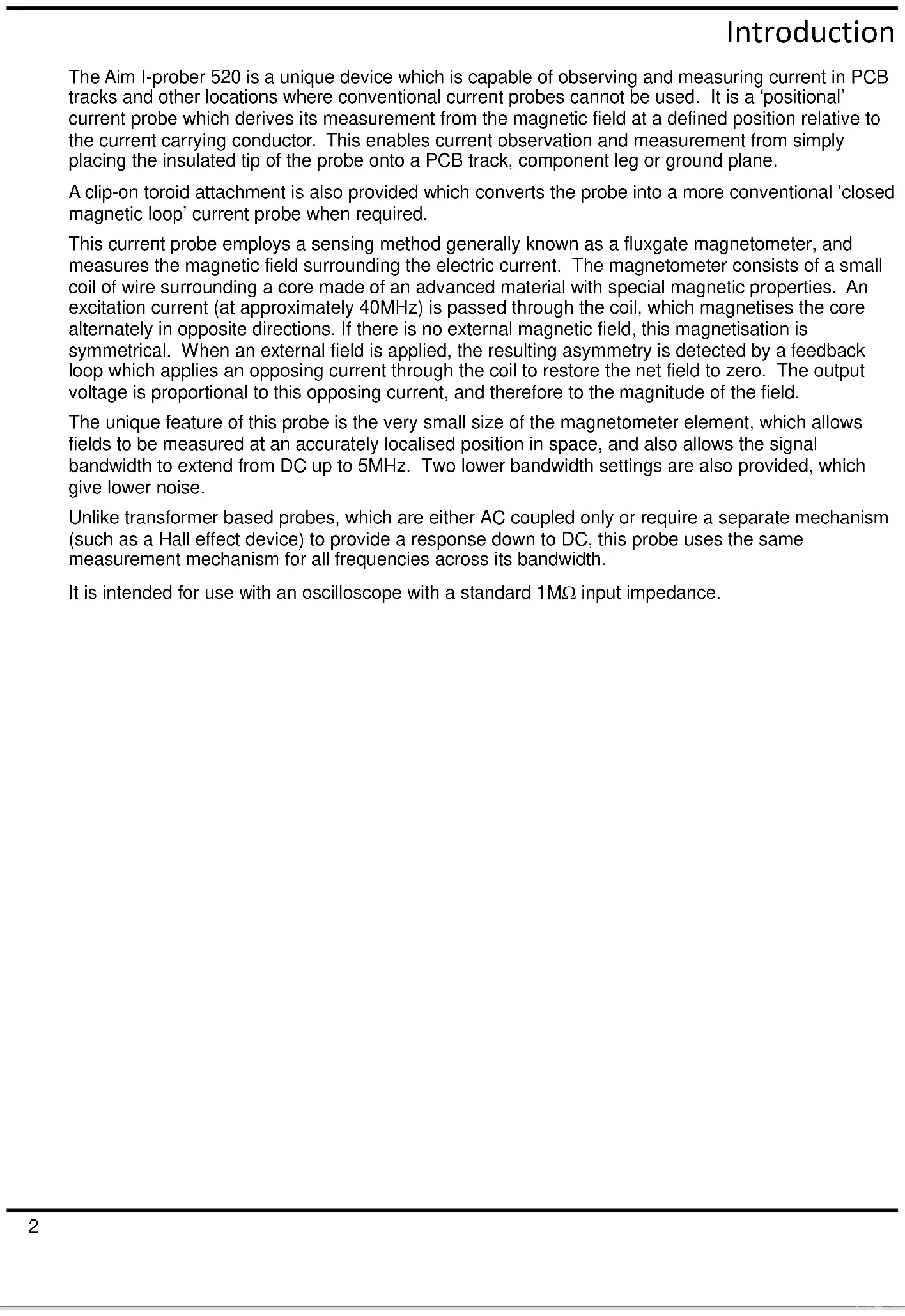
The relationship between the output voltage seen on the scope and the actual current in the PCB track depends on a complex relationship between the width of the track, the width of the sensor inside the current probe, and the thickness of the probe insulation between the track and that sensor. To obtain quantitative measurements the sensitivity adjustment on the control box must set to suit the particular track width being measured. The wider the track, the lower the field strength for a given current, so the greater the gain required to obtain a sensitivity of 1A/V. At track widths above about 3.5mm the control box gain cannot be increased sufficiently to give a sensitivity of 1A/V so the system must be adjusted for a sensitivity of 2A/V.
This relationship between track width and the gain required is incorporated into the calibration graph below. The calibration procedure involves placing the probe into the calibration hole in the control box and applying the calibration current. The sensitivity control is then adjusted to obtain the particular output voltage (as measured by the scope trace) to suit the intended track width. The calibrator can produce either a square wave or DC calibration current. To avoid difficulties caused by the influence of the earth's magnetic field and the local magnetic environment, calibration is normally performed using the square wave signal, obtained by setting the switch to the AC ( _L ) position. The signal is a square wave at about 1kHz. The amplitude setting refers to the peak-to-peak voltage between the flat parts of the square wave, ignoring any overshoot on the transitions.
Detailed Procedure
First, decide on the width of the track for which a calibrated measurement is required. Then, using the graph, look up the peak-to-peak output voltage setting for that track width and set the scope to a suitable sensitivity (for example, 1 Volt per division for narrow tracks, or 0.5 Volt per division for wider tracks).
I-prober 520 PCB sensitivity setting
— For 1 Amp/Volt ---- For 2 Amp/Volt
line
| Track Width (mm) | Calibrator output (Vpp) - Solid Line | Calibrator output (Vpp) - Dashed Line | | ---------------- | ------------------------------------ | ------------------------------------- | | 0 | 1.8 | 1.5 | | 1 | 1.9 | 1.6 | | 2 | 2.0 | 1.7 | | 3 | 2.1 | 1.8 | | 4 | 2.3 | 1.9 | | 5 | 2.5 | 2.0 | | 6 | 2.7 | 2.2 | | 7 | 3.4 | 2.7 |Insert the probe into the calibration recess and turn on the calibration signal by setting the CALIBRATOR switch to the AC position (marked ☐). Optimise the orientation of the probe within the calibrator recess to obtain the maximum signal amplitude on the scope, then adjust the Trace Position control to centre the trace on the screen.
Adjust the PCB Sensitivity control so that the peak-to-peak voltage of the scope trace (ignoring overshoot) equals the value obtained from the calibration graph for the required track width. The probe sensitivity is now set to give either 1A/V or 2A/V (depending on which calibration curve is used) for measurements on the actual PCB track.
Switch off the calibration signal by returning the CALIBRATOR switch to its centre position.
For tracks wider than 6.5mm, it can be assumed that the reading is inversely proportional to the track width plus 2.2mm. Alternatively, switch to Magnetic Field mode and measure the field in Amps per metre. This can be converted to Amps, by assuming that the path length is twice the width of the track plus 4.4mm (this figure accounts for the fact that the sensor is 0.7mm above the track surface). This relationship assumes that the track is long in relation to its width and reasonably uniform in layout.
Practical Aspects of Quantitative Measurements
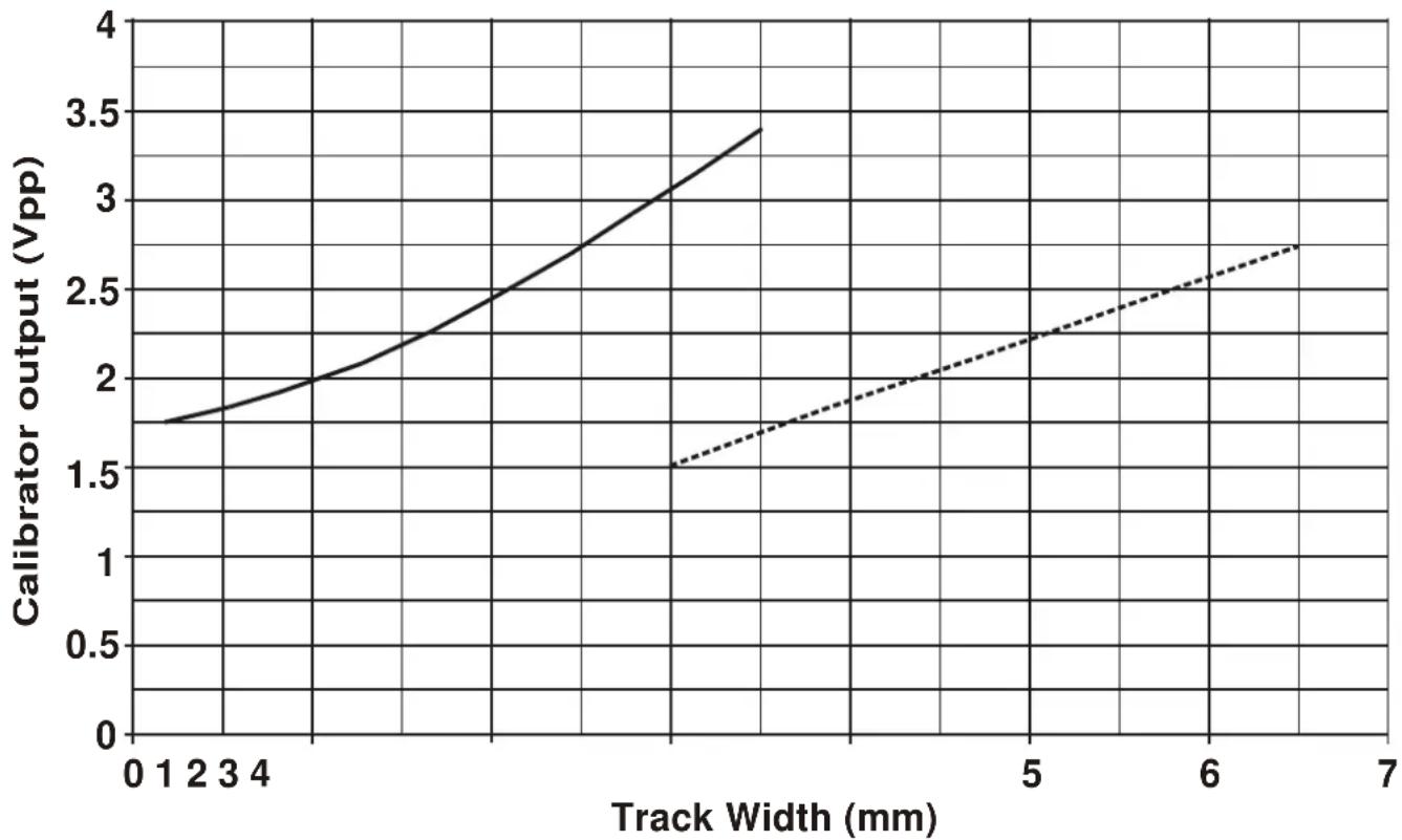
To accurately measure the current in a track the probe must be precisely positioned vertically in two dimensions, placed exactly above the centre of the track and aligned with the long dimension of the tip at right angles to the track.
The diagram shows the proper orientation. If the probe is not aligned at right angles across the track (yaw), the output varies according to a sine law, so small errors are tolerable; similarly, rotating the probe forwards or backwards around its rounded tip (pitch) does not cause major errors. The most critical position requirements are the centring over the track, and being vertical side to side (roll), so that the probe is flat on the track, not canted up on the corner of its tip.

Avoid the temptation to manipulate the probe tip with the fingers, unless it is certain that there are no dangerous voltages present.
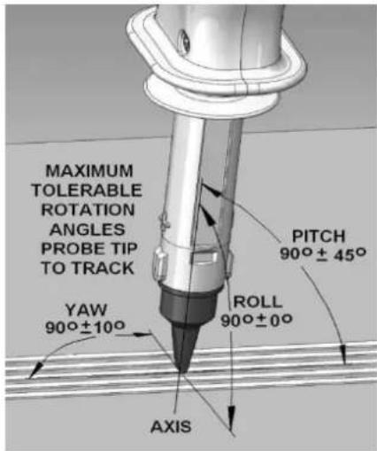
text_image
MAXIMUM TOLERABLE ROTATION ANGLES PROBE TIP TO TRACK YAW 90°±10° ROLL 90°±0° AXIS PITCH 90°±45°In the absence of uneven extraneous fields the correct position is the one giving the greatest output but it will be found that, in an environment containing many magnetic materials, the localised magnetic field can vary substantially in both magnitude and direction from the earth's North-South field that exists in free space. As a result, even small movements in the position of the probe can have a significant effect on the residual output voltage. The best way to minimise the effect of this is to place the probe in the required location on the track to be measured, switch the current off and set the zero position, then switch the current on and note its magnitude. Many of these difficulties can be avoided if an AC measurement is possible.
When measuring small currents (small in relation to the effect of the magnetic field of the local environment) it is helpful if the probe can be held fixed in space (by using a retort stand or similar device) and moving the signal being tested under the fixed probe.
Note that the calibration procedure given above only gives accurate results when the measurement is on an isolated track some distance from any other current. Adjacent tracks carrying currents, including those on the other side of the PCB, will have a significant effect on the measurement. Obtaining a quantitative result in such circumstances requires mathematical analysis from first principles.
Maintenance
The Manufacturers or their agents overseas will provide a repair service for any unit developing a fault.
Cleaning
If the instrument requires cleaning use a cloth that is only lightly dampened with water or a mild detergent.
WARNING! TO AVOID ELECTRIC SHOCK, OR DAMAGE TO THE INSTRUMENT, NEVER ALLOW WATER TO GET INSIDE THE CASE. TO AVOID DAMAGE TO THE CASE NEVER CLEAN WITH SOLVENTS.
Tip Insulation
If the insulation of the probe tip becomes worn or damaged so that the inner layer of insulation shows through, contact the Manufacturers or their agents overseas.
Calibration
The fundamental calibration parameter is magnetic field; calibration requires a calibrated field from a precision Helmholtz coil. The manufacturer can provide a suitable re-calibration service in the event that the local calibration service is unable to do so.
However, if only a current-in-wire re-calibration (with the toroid attachment) is required, this can be achieved using a more widely available standard DMM calibrator. Calibration is performed using a 50 or 60Hz sine wave. Take care to establish a repeatable position of the cable within the opening in the toroid; this is normally opposite the probe tip and as far back as possible.
Web link
For support please visit http://www.aimtti.com/support.
Introduction
Courant continu (CC)