TGF4242 - Generator Aim TTi - Free user manual and instructions
Find the device manual for free TGF4242 Aim TTi in PDF.
| Product type | Function/arbitrary/pulse generator dual channel 240 MHz |
| Brand | Aim TTi |
| Model | TGF4242 |
| Maximum frequency | 240 MHz (sine) |
| Number of channels | 2 |
| Waveforms | Sine, square, ramp, pulse, noise, PRBS, arbitrary |
| Modulations | AM, AM-SC, FM, PM, PWM, ASK, FSK |
| Sweep and burst | Frequency sweep, triggered burst |
| Output amplitude | Up to 10 Vpp into 50 Ω (peak-to-peak) |
| Output impedance | 50 Ω (adjustable up to 10 kΩ in high impedance) |
| Power supply | 100-240 VAC, 50/60/400 Hz, 60 VA max |
| Dimensions (approx.) | 320 x 180 x 450 mm |
| Weight (approx.) | 4 kg |
| Interfaces | LAN (LXI Core 2011), USB, GPIB (option), reference input/output, trigger/counter input, modulation input |
| Memory | Internal non-volatile memory, USB storage (host port) |
| Frequency counter | Built-in, AC and DC inputs |
| Safety class | Class 1 per EN61010-1, Installation category II |
| Internal battery | CR2032 lithium coin cell, 3 V, life ~5 years |
| Fuse | Replacement fuse of specified type and rating (see manual) |
| Cleaning | Soft damp cloth (water or mild detergent), do not use solvents |
| Operating temperature | 5°C to 40°C, 20%-80% RH (non-condensing) |
| Included accessories | Power cord, user manual |
Frequently Asked Questions - TGF4242 Aim TTi
User questions about TGF4242 Aim TTi
0 question about this device. Answer the ones you know or ask your own.
Ask a new question about this device
Download the instructions for your Generator in PDF format for free! Find your manual TGF4242 - Aim TTi and take your electronic device back in hand. On this page are published all the documents necessary for the use of your device. TGF4242 by Aim TTi.
USER MANUAL TGF4242 Aim TTi
Quick Guide in English....2
Guide Succinct en Français 43
Kurzanleitung....83
Guida Rapida in Italiano....123
Specification....203
TABLE OF CONTENTS
- Introduction....3
The TGF4000 Series of Arbitrary Function Generators....3
About this Guide....3
- Safety......4
General....4
Symbols 5
- Operational Principles......6
Front Panel Layout 6
Rear Panel Layout....7
Screen Layout....8
-
Getting Started....9
-
Basic Set-up Examples....10
Setting-up a Sine Wave Signal ....10
Setting-up a Square Wave Clock Signal ....14
Setting-up a Pulse Waveform 20
Setting-up more Output Options 28
Requirement 28
- Exploring the Generator Capabilities....32
Setting-up an arbitrary wave signal....32
Setting-up an AM modulated Sine Waveform....33
PRBS 34
Frequency Modulation of a Sine Waveform....35
Pulse Width Modulated Waveform (PWM) 36
Amplitude shift keying (ASK) 37
Frequency Sweep of a Sine Wave....38
Generating a Triggered Burst....39
Coupling the Frequency of Both Channels....40
Frequency counter 41
- Maintenance....42
Cleaning 42
The latest revisions of this manual, device drivers and software tools can be downloaded from: http://www.aimtti.com/support
1. INTRODUCTION
The TGF4000 Series of Arbitrary Function Generators
This manual covers all four TGF4000 dual channel generators. Where there are differences in the specification, the limits for the TGF4042 & TGF4082 are shown in square brackets [ ] after the TGF4162 & TGF4242 limits.
These programmable function/arbitrary generators use direct digital synthesis techniques to provide high performance and extensive facilities in a compact instrument. They generate a wide variety of waveforms with high resolution and accuracy.
Sine waves are produced with low distortion to 160MHz/240MHz [40MHz/80MHz]. Square waves have fast rise and fall times at up to 100MHz [25MHz]. Linear ramp waves are produced to 5MHz. Ramp and square waves also have variable symmetry.
The instruments generate high resolution, low jitter, variable edge time pulses to 100MHz [25MHz] with variable period, pulse width, pulse delay, pulse edges and amplitude. Complex custom waveforms can be generated with 16-bit [14-bit] resolution and a sampling rate of 800MSa/s [400MSa/s]. Up to four waveforms can be stored in internal memory. Waveforms can also be generated by the supplied Waveform Manager Plus V4.13 Windows application and downloaded to the instrument via USB, LAN or optional GPIB interfaces or via a USB flash drive.
Front panel operation is straightforward and user friendly with all major parameters shown at all times on the large, bright, colour LCD. All major functions can be accessed with a single key or two. The knob or numeric keypad can be used to adjust frequency, amplitude, offset, and other parameters. Voltage values can be entered directly in Vpp or as high and low levels. Timing parameters can be entered in Hertz (Hz) or seconds.
Internal AM, FM, PM, ASK, FSK, BPSK, SUM* and PWM modulation make it easy to modulate waveforms without the need for a separate modulation source. Linear and logarithmic sweeps are also built in, with sweep rates selectable from 1 s to 500s. Burst mode operation allows for a user-selected number of cycles at each trigger event.
LAN and USB interfaces are standard and there is full compliance to 1.5 LXI Device Specification 2016.
The instruments use a high stability temperature compensated internal oscillator and the external frequency reference input lets you synchronize to an external 10 MHz frequency standard for even greater accuracy.
*TGF4162 & TGF4242 only
About this Guide
This Quick Start guide is for bench-top use of the TGF4000 Series comprising the TGF4042,TGF4082, TGF4162 and TGF4242 dual channel generators. A full Instruction Manual (English only) is also provided on the Aim-TTi website that includes comprehensive explanations of all functions and additional information on remote control, calibration, and the detailed technical specifications.
2. SAFETY
General
This generator is a Safety Class I instrument according to IEC classification and has been designed to meet the requirements of EN61010-1 (Safety Requirements for Electrical Equipment for Measurement, Control and Laboratory Use). It is an Installation Category II instrument intended for operation from a normal single phase supply.
This instrument has been tested in accordance with EN61010-1 and has been supplied in a safe condition. This instruction manual contains some information and warnings which have to be followed by the user to ensure safe operation and to retain the instrument in a safe condition.
This instrument has been designed for indoor use in a Pollution Degree 2 environment in the temperature range 5^ C to 40^ C, 20% – 80% RH (non-condensing). It may occasionally be subjected to temperatures between +5^ and -10^ C without degradation of its safety. Do not operate while condensation is present.
Use of this instrument in a manner not specified by these instructions may impair the safety protection provided. Do not operate the instrument outside its rated supply voltages or environmental range.
WARNING! THIS INSTRUMENT MUST BE EARTHED
Any interruption of the mains earth conductor inside or outside the instrument will make the instrument dangerous. Intentional interruption is prohibited. The protective action must not be negated by the use of an extension cord without a protective conductor.
When the instrument is connected to its supply, terminals may be live and opening the covers or removal of parts (except those to which access can be gained by hand) is likely to expose live parts. The apparatus shall be disconnected from all voltage sources before it is opened for any adjustment, replacement, maintenance or repair. Any adjustment, maintenance and repair of the opened instrument under voltage shall be avoided as far as possible and, if inevitable, shall be carried out only by a skilled person who is aware of the hazard involved.
If the instrument is clearly defective, has been subject to mechanical damage, excessive moisture or chemical corrosion the safety protection may be impaired and the apparatus should be withdrawn from use and returned for checking and repair.
Make sure that only fuses with the required rated current and of the specified type are used for replacement. The use of makeshift fuses and the short-circuiting of fuse holders is prohibited.
This instrument uses a Lithium button cell for non-volatile memory battery back-up; typical life is 5 years. In the event of replacement becoming necessary, replace only with a cell of the correct type, i.e. 3V Li/MnO _2 20mm button cell type 2032. Exhausted cells must be disposed of carefully in accordance with local regulations; do not cut open, incinerate, expose to temperatures above 60°C or attempt to recharge.
Do not wet the instrument when cleaning it and in particular use only a soft dry cloth to clean the LCD window.
Symbols
The following symbols are used on the instrument and in this manual:

Caution – refer to the accompanying documentation, incorrect operation may damage the instrument.

Terminal connected to chassis ground.

Mains supply OFF.

Mains supply ON.

Alternating current.
3. OPERATIONAL PRINCIPLES
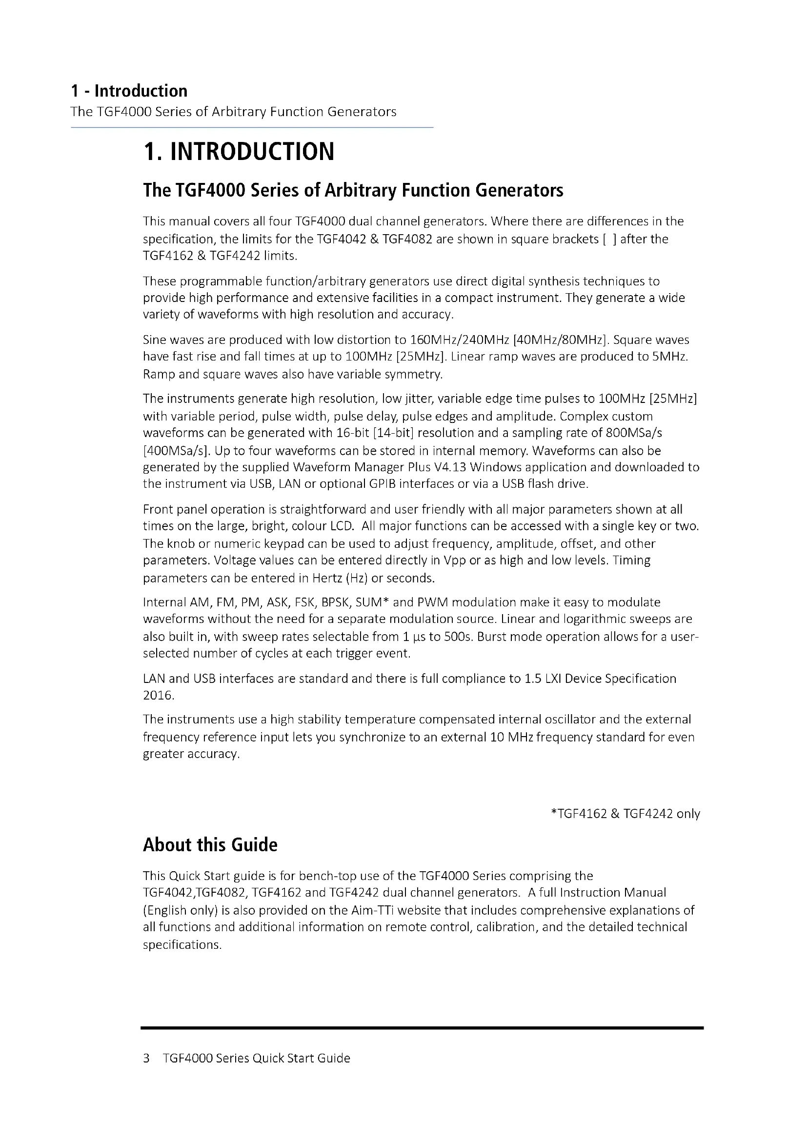
Front Panel Layout
text_image
240MHz Dual Function/Arb/Pulse Generator TGF4242 LXI FLASH DRIVE Sine On Frequency: 50.0000MHz Amplitude: 1.000 Vpp Offset: +0.000 Voc Modulation: AM-SC AM Freq: Not Applicable Depth: 80.00 % Shape: Noise CH1 Main Menu 50.000 000 000 000MHz Freq Ampl Offset Output Wave 7 8 9 Params 4 5 6 Mod 1 2 3 Swamp 0 • +/- Burst Ch1 Output 1 Output 2 Ch2 LOOM Trigger Utility 50 Ω 50 Ω POWER~ ① ② ③ ④ ⑤ ⑥ ⑦ ⑧| Ref. | Short Description | Function |
| 1 | Power Switch | Switches instrument on or off. Safety Note: To fully disconnect from the AC supply, unplug the mains cord from the back of the instrument or switch off at the AC supply outlet; make sure that the means of disconnection is readily accessible. |
| 2 | Soft-keys | Performs the function shown on the LCD soft-key label above. |
| 3 | Waveform Keys | Selects the main waveform type (carrier waveform) as active. (Sine, Square, Ramp, Pulse, Noise/PBRS or Arb.) |
| 4 | Waveform Modification Menus | Opens menus for setting parameters for Modulation, Sweep and Burst |
| 5 | Other Menus | Selects menus for internal and external file storage, instrument utilities, and trigger conditions. |
| 6 | Main Sockets | Main output sockets. Channel 2 can also be configured to output Channel 1 sync from its MAIN OUT 2 socket. |
| 7 | Output Keys | Switch the selected MAIN OUT on or off. |
| 8 | Cursor Keys and Spin Wheel | Used to change numeric parameter values digit by digit. Used to select items within some menus. |
| 9 | Numeric Keypad | Used to enter numeric parameter values directly. |
| 10 | USB Flash Drive | USB Host connector for USB Flash drive storage. |
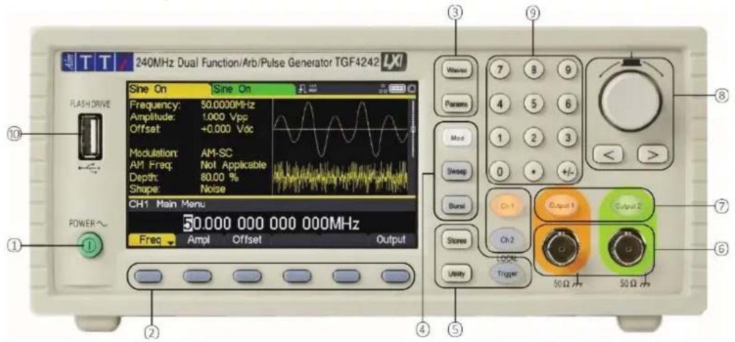
Rear Panel Layout
text_image
RATED VOLTAGE: 100-240VAC - 50/KB/400Hz POWER: 60VA MAX WARNING: THIS APPARATUS NUST BE EARTHED MOD IN +5V MAX 5kΩ REF / COUNT (AC) IN +10V 5Vpp MAX REF OUT +5V-1V MAX 10kΩ TRIG / COUNT (DC) IN +5V-1V MAX 10kΩ WARNING: THIS PRODUCT CONTAINS A LITHUM BATTERY WHICH MUST NOT BE CUT OPEN, INCINERATED, EXPOSED TO TEMPERATURES ABOVE +40°C OR RECHARGED DISPAGE OF AS SPECIFIED IN LOCAL REGULATIONS. LAN USB ① ② ③ ④ ⑤ ⑥ ⑦| Ref. | Short Description | Function |
| 1 | Modulation Input | Input for external modulation of main waveforms. |
| 2 | Reference In / AC coupled frequency counter | Input for external 10MHz reference clock and AC coupled external frequency measurement. |
| 3 | Reference Out | Output for internal 10MHz reference clock. |
| 4 | Trigger Input / DC coupled frequency counter | Input for external triggering of main waveforms and DC coupled external frequency measurement |
| 5 | LAN connection | Designed to meet LXI Core 2011.Remote control is possible using the TCP/IP Socket protocol. |
| 6 | USB connection | Accepts a standard USB cable. |
| 7 | GPIB connection (optional) | IEEE-488 The default GPIB address is 5. |
3 - Operational Principles
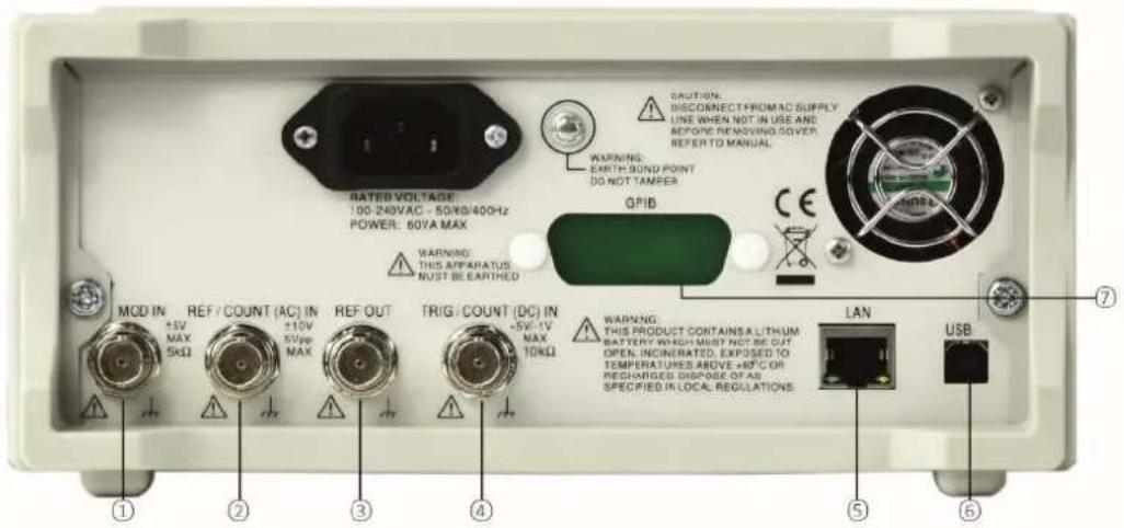
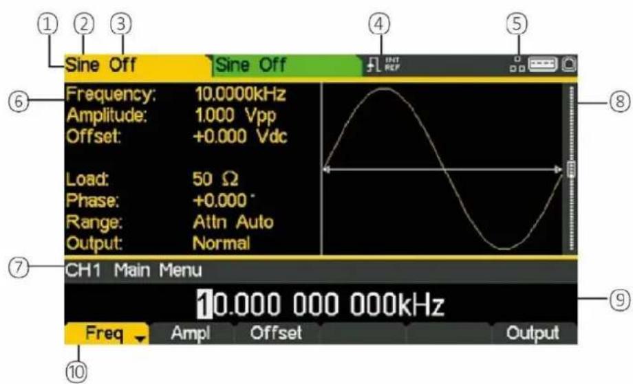
Screen Layout
Screen Layout
text_image
Sine Off Frequency: 10.0000kHz Amplitude: 1.000 Vpp Offset: +0.000 Vdc Load: 50 Ω Phase: +0.000° Range: Attn Auto Output: Normal CH1 Main Menu 10.000 000 000kHz Freq Ampl Offset Output ① ② ③ ④ ⑤ ⑥ ⑦ ⑧ ⑨| Ref. | Short Description | Function |
| 1 | Channel Indicator | Shows currently selected channel |
| 2 | Main Waveform type | Shows current carrier waveform |
| 3 | Output State | Shows main output On or Off |
| 4 | External Clock Indicator | Shows status of external clock (if applied) |
| 5 | LAN Status Indicator | Shows status of LAN (Ethernet) connection. |
| 6 | Parameters Box | Shows main parameters for waveform. |
| 7 | Menu Description | Shows the currently selected editing menu. |
| 8 | Graph Box | Shows a graphical representation of the selected waveform. |
| 9 | Edit Box | Shows the current parameter that can be edited |
| 10 | Soft-key Labels | Shows the current functions for the six keys below. |
4. GETTING STARTED
In order to familiarise the user with some of the basic functionalities of the instrument, a number of set-up examples are shown in this guide.
It is recommended that all users should carry out the first four examples:
• Setting-up a Sine Wave Signal
- Setting-up a Square Wave Clock Signal
- Setting-up a Pulse Waveform
- Setting-up more Output Options
A number of further set-up examples are provided that assume some familiarity with the instrument:
- Setting-up an arbitrary wave signal
- Setting-up an AM modulated Sine Waveform
• P RBS (TGF4162 & TGF4242)
• Frequency Modulation of a Sine Waveform
• Pulse Width Modulated Waveform (PWM)
• Amplitude shift keying (ASK)
• Frequency Sweep of a Sine Wave
• Generating a Triggered Burst
• Coupling the Frequency of Both Channels - Frequency counter
For more detailed information on all functionality- see the full Instruction Manual.
Initial Conditions
Before setting up the instrument for any of the examples, it should be returned to default conditions. To do this follow these steps:
- Press the hard key marked Utility
- Press the soft-key labelled System
- Press the soft-key labelled Default (display will show Restore Factory Default?)
- Press the soft-key labelled Yes
This sets the main waveform to Sine (10kHz, 1V pk-pk) and cancels any modulations, sweep, or burst triggering or gating.
NOTE

The instrument can be set to remember its latest settings on power-off and restore them at power-on. This is set from the Utility > System menu and the PwrOn soft-key. This setting will be lost when the instrument is restored to default conditions as described above.
5. BASIC SET-UP EXAMPLES
Setting-up a Sine Wave Signal
Requirement
Output a continuous sine wave signal with 40MHz frequency and an amplitude of 6 volts pk-pk from MAIN OUT 1.
Starting Conditions
Before starting, reset the instrument to defaults as described in section 4 Getting Started
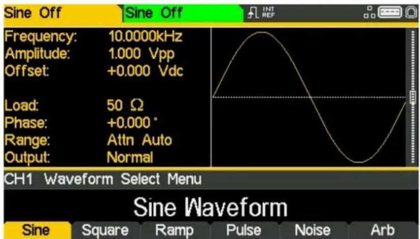
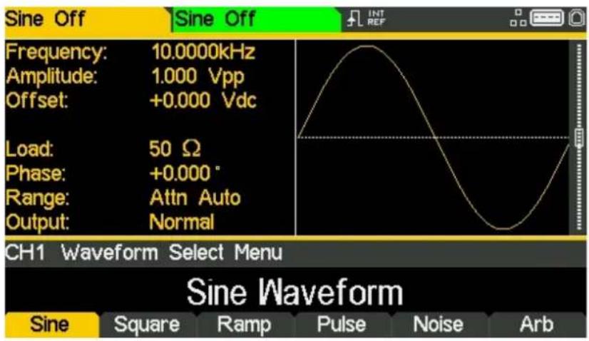
Open Waveform Menu - Sine
- Press the hard key marked Waves

text_image
Sine Off Frequency: 10.0000kHz Amplitude: 1.000 Vpp Offset: +0.000 Vdc Load: 50 Ω Phase: +0.000° Range: Attn Auto Output: Normal CH1 Waveform Select Menu Sine Waveform Sine Square Ramp Pulse Noise Arb- Press the soft key labelled Sine
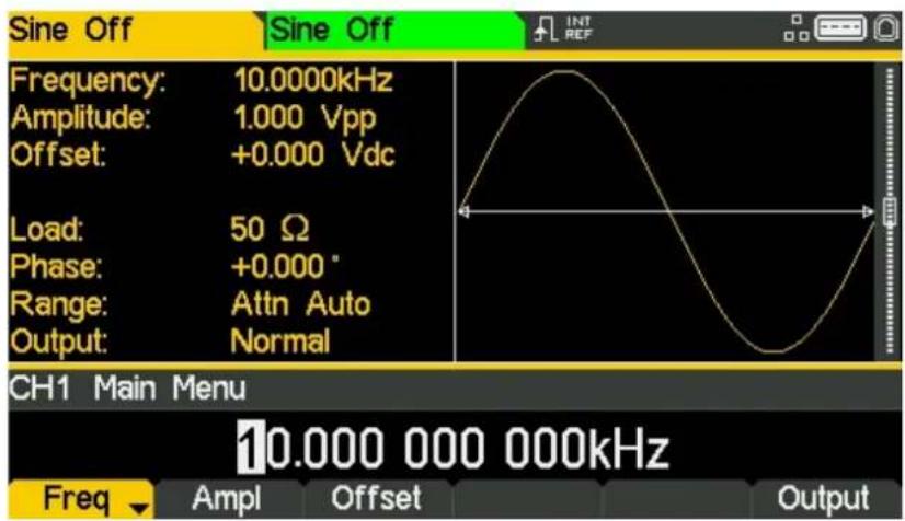
text_image
Sine Off Frequency: 10.0000kHz Amplitude: 1.000 Vpp Offset: +0.000 Vdc Load: 50 Ω Phase: +0.000° Range: Attn Auto Output: Normal CH1 Main Menu 10.000 000 000kHz Freq Ampl Offset OutputSet the Frequency
The soft key labelled Freq will be highlighted- the current frequency appears in the edit box. Pressing this soft-key repeatedly changes its function between Frequency and Period.
• Use the numeric keypad to enter a new frequency. Press the numbers 4 0
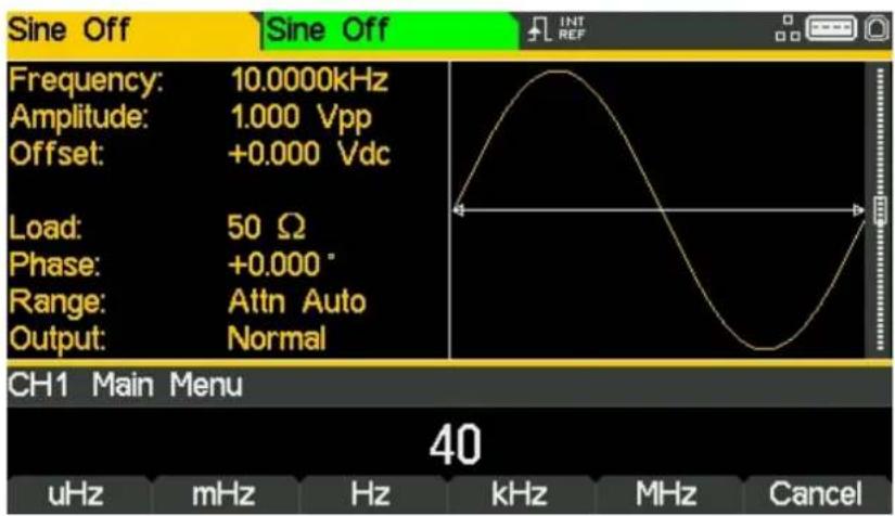
text_image
Sine Off Frequency: 10.0000kHz Amplitude: 1.000 Vpp Offset: +0.000 Vdc Load: 50 Ω Phase: +0.000° Range: Attn Auto Output: Normal CH1 Main Menu 40 uHz mHz Hz kHz MHz CancelAs soon as a number is entered, the soft-keys change to show units of frequency.
- Press the soft-key labelled MHz to confirm a frequency of 40MHz.
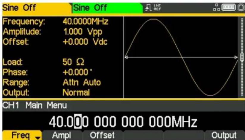
text_image
Sine Off Frequency: 40.0000MHz Amplitude: 1.000 Vpp Offset: +0.000 Vdc Load: 50 Ω Phase: +0.000 ° Range: Attn Auto Output: Normal CH1 Main Menu 40.000 000 000 000MHz Freq Ampl Offset OutputSet the Amplitude
- Press the soft key labelled Ampl
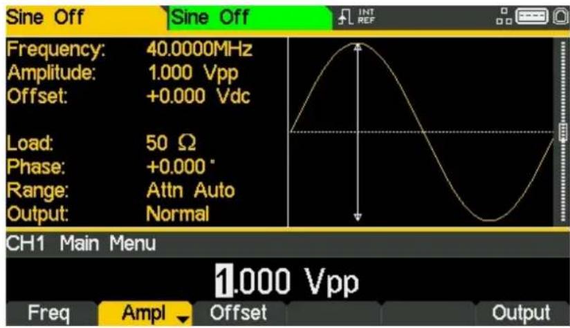
text_image
Sine Off Frequency: 40.0000MHz Amplitude: 1.000 Vpp Offset: +0.000 Vdc Load: 50 Ω Phase: +0.000 ° Range: Attn Auto Output: Normal CH1 Main Menu 1.000 Vpp Freq Ampl Offset OutputSuccessive presses of the Ampl soft-key changes the Ampl and Offset key labels to HiLvl (high level) and LoLvl (low level) and vice versa.
• Use the numeric keypad to enter a new amplitude. Press the number 6
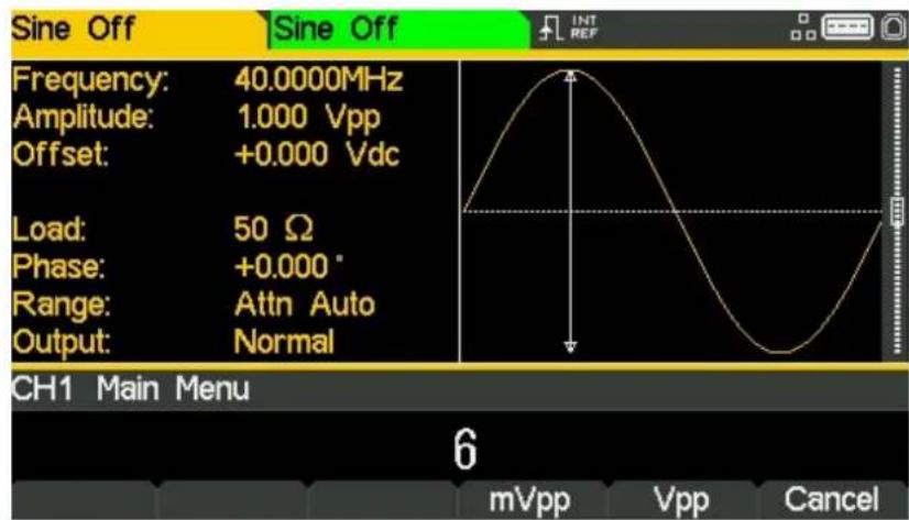
text_image
Sine Off Frequency: 40.0000MHz Amplitude: 1.000 Vpp Offset: +0.000 Vdc Load: 50 Ω Phase: +0.000° Range: Attn Auto Output: Normal CH1 Main Menu 6 mVpp Vpp CancelAs soon as a number is entered, the soft-keys change to show units of voltage.
5 - Basic Set-up Examples
Setting-up a Sine Wave Signal
- Press the soft-key labelled Vpp to confirm a pk-pk amplitude of 6.0 volts.
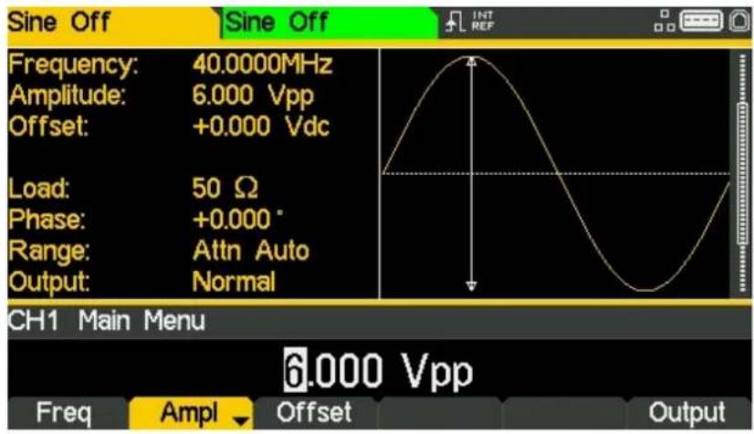
text_image
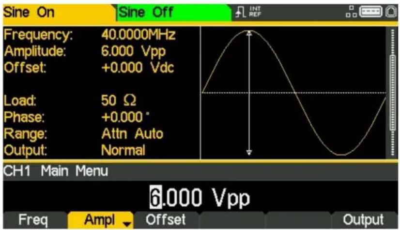
Sine Off Frequency: 40.0000MHz Amplitude: 6.000 Vpp Offset: +0.000 Vdc Load: 50 Ω Phase: +0.000° Range: Attn Auto Output: Normal CH1 Main Menu Freq Ampl Offset Output 6.000 VppTurn the Output On
- Press Output 1 key to turn the channel 1 output On.
text_image
Sine On Sine Off Frequency: 40.0000MHz Amplitude: 6.000 Vpp Offset: +0.000 Vdc Load: 50 Ω Phase: +0.000° Range: Attn Auto Output: Normal CH1 Main Menu 6.000 Vpp Freq Ampl Offset OutputThe Output 1 key illuminates orange to indicate the on state.
Setting-up a Square Wave Clock Signal
Requirement
Output a continuous square wave clock signal with 20MHz frequency, 50% duty cycle and a high level of 3.3V and a low level of 0.0 volts from MAIN OUT 1.
Starting Conditions
Before starting, reset the instrument to defaults as described in section 4 Getting Started
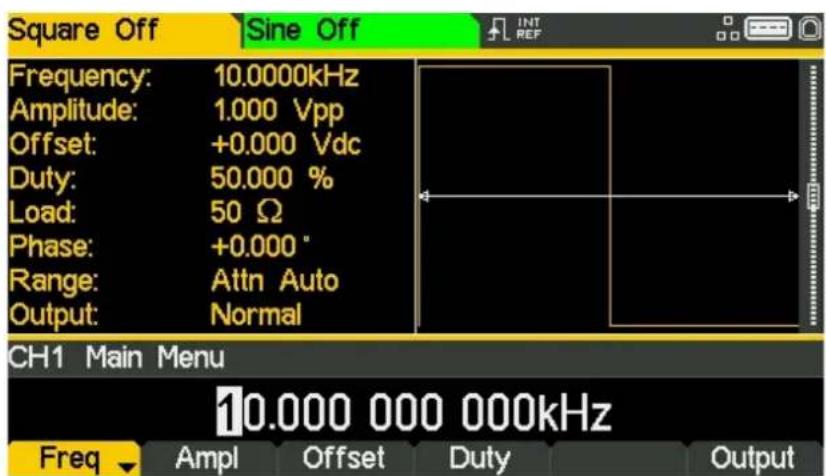
Open Waveform Menu - Square
- Press the hard key marked Waves
text_image
Sine Off Frequency: 10.0000kHz Amplitude: 1.000 Vpp Offset: +0.000 Vdc Load: 50 Ω Phase: +0.000° Range: Attn Auto Output: Normal CH1 Waveform Select Menu Sine Waveform Sine Square Ramp Pulse Noise Arb- Press the soft-key labelled Square.
text_image
Square Off Sine Off Frequency: 10.0000kHz Amplitude: 1.000 Vpp Offset: +0.000 Vdc Duty: 50.000 % Load: 50 Ω Phase: +0.000° Range: Attn Auto Output: Normal CH1 Main Menu 10.000 000 000kHz Freq Ampl Offset Duty Output+
Set the Frequency
The soft key labelled Freq will be highlighted- the current frequency appears in the edit box.
Pressing this soft-key repeatedly changes its function between Frequency and Period.
• Use the numeric keypad to enter a new frequency. Press the numbers 20
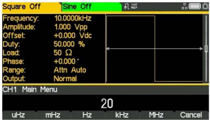
text_image
Square Off Sine Off Frequency: 10.0000kHz Amplitude: 1.000 Vpp Offset: +0.000 Vdc Duty: 50.000 % Load: 50 Ω Phase: +0.000° Range: Attn Auto Output: Normal CH1 Main Menu 20 uHz mHz Hz kHz MHz CancelAs soon as a number is entered, the soft-keys change to show units of frequency.
- Press the soft-key labelled MHz to confirm a frequency of 20MHz.
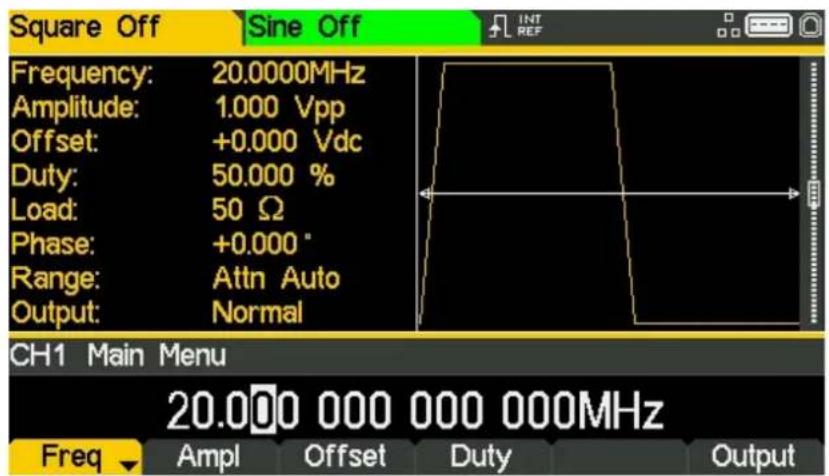
text_image
Square Off Sine Off Frequency: 20.0000MHz Amplitude: 1.000 Vpp Offset: +0.000 Vdc Duty: 50.000 % Load: 50 Ω Phase: +0.000 ° Range: Attn Auto Output: Normal CH1 Main Menu 20.000 000 000 000MHz Freq Ampl Offset Duty OutputThe graph box changes to show the rise time on the edges which is now significant.
5 - Basic Set-up Examples
Setting-up a Square Wave Clock Signal
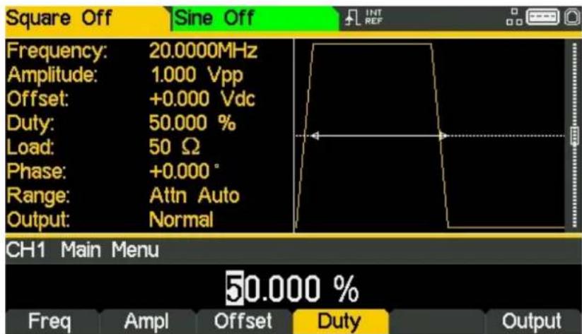
Confirm the Duty Cycle
- Press the soft-key labelled Duty - the current duty cycle appears in the edit box.
text_image
Square Off Sine Off Frequency: 20.0000MHz Amplitude: 1.000 Vpp Offset: +0.000 Vdc Duty: 50.000 % Load: 50 Ω Phase: +0.000° Range: Attn Auto Output: Normal CH1 Main Menu 50.000 % Freq Ampl Offset Duty OutputThe duty cycle is already set at 50%, but could be changed here if required.
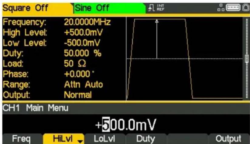
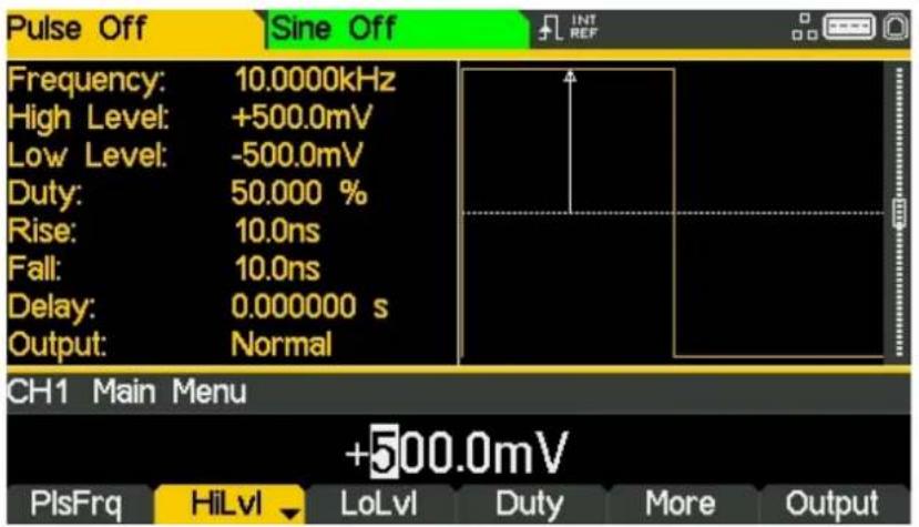
Set the High and Low Levels
- Press the soft-key labelled Ampl - the key label changes to HiLvl and the current high level voltage appears in the edit box.
text_image
Square Off Sine Off Frequency: 20.0000MHz High Level: +500.0mV Low Level: -500.0mV Duty: 50.000 % Load: 50 Ω Phase: +0.000 ° Range: Attn Auto Output: Normal CH1 Main Menu +500.0mV Freq HiLvl LoLvl Duty OutputSuccessive presses of the Ampl soft-key changes the Ampl and Offset key labels to HiLvl (high level) and LoLvl (low level) and vice versa.
5 - Basic Set-up Examples
Setting-up a Square Wave Clock Signal
When the soft-key is labelled HiLvl - the current high level voltage appears in the edit box.
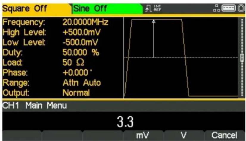
• Use the numeric keypad to enter a new level. Press the numbers 3 . 3
text_image
Square Off Sine Off Frequency: 20.0000MHz High Level: +500.0mV Low Level: -500.0mV Duty: 50.000 % Load: 50 Ω Phase: +0.000 ° Range: Attn Auto Output: Normal CH1 Main Menu 3.3 mV V CancelAs soon as a number is entered, the soft-keys change to show units of voltage.
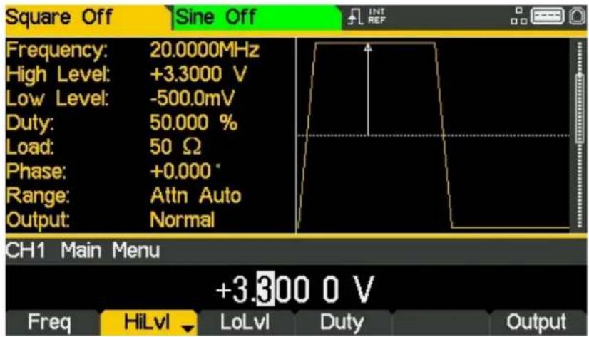
- Press the soft-key labelled V to confirm a high level of 3.3 volts.
text_image
Square Off Sine Off Frequency: 20.0000MHz High Level: +3.3000 V Low Level: -500.0mV Duty: 50.000 % Load: 50 Ω Phase: +0.000 ° Range: Attn Auto Output: Normal CH1 Main Menu +3.300 0 V Freq HiLvl LoLvl Duty Output5 - Basic Set-up Examples
Setting-up a Square Wave Clock Signal
- Press the soft-key labelled LoLvl - the current low level voltage appears in the edit box.
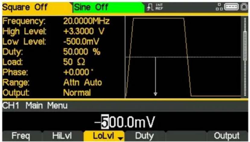
text_image
Square Off Sine Off Frequency: 20.0000MHz High Level: +3.3000 V Low Level: -500.0mV Duty: 50.000 % Load: 50 Ω Phase: +0.000 ° Range: Attn Auto Output: Normal CH1 Main Menu -500.0mV Freq HiLvl LoLvl Duty Output• Use the numeric keypad to enter a new level. Press 0
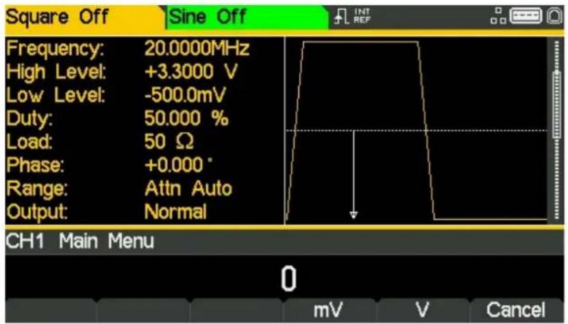
text_image
Square Off Sine Off Frequency: 20.0000MHz High Level: +3.3000 V Low Level: -500.0mV Duty: 50.000 % Load: 50 Ω Phase: +0.000 ° Range: Attn Auto Output: Normal CH1 Main Menu 0 mV V Cancel- Press the soft-key labelled V to confirm a low level of 0.0 volts.
Turn the Output On
- Press Output 1 key to turn the channel 1 output On.
The Output 1 key illuminates orange to indicate the on state
Making live changes to any numeric parameter (e.g. Frequency)
Numeric parameters can be changed by using the cursor keys and spin wheel as an alternative to the numeric keypad.
- Press the hard key marked Waves
- Press the soft-key labelled Square.
- Press the soft-key labelled Freq – the current frequency value of 20.0MHz is displayed
- Press the Cursor hard keys to move the edit highlight to the second digit.
- Use the spin wheel to change the value – the frequency is changed immediately.
NOTE

Press to activate/ deactivate the spin wheel.
Setting-up a Pulse Waveform
Requirement
Output a continuous pulse signal with 100ns period, 30ns pulse width, 20ns edge times and a high level of 2.7V and a low level of -0.6 volts from MAIN OUT 1.
Starting Conditions
Before starting, reset the instrument to defaults as described in section 4 Getting Started
Open Waveform Menu - Pulse
- Press the hard key marked Waves
text_image
Sine Off Frequency: 10.0000kHz Amplitude: 1.000 Vpp Offset: +0.000 Vdc Load: 50 Ω Phase: +0.000° Range: Attn Auto Output: Normal CH1 Waveform Select Menu Sine Waveform Sine Square Ramp Pulse Noise Arb- Press the soft-key labelled Pulse.
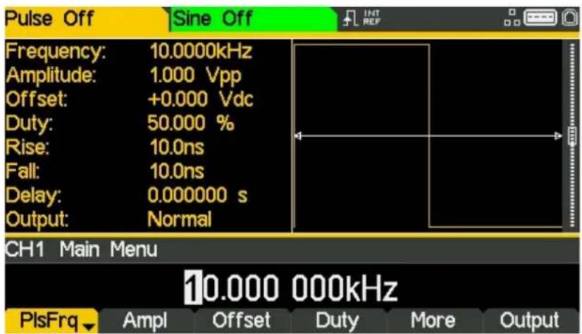
text_image
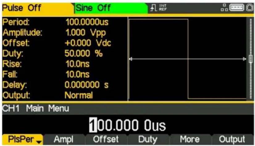
Pulse Off Sine Off Frequency: 10.0000kHz Amplitude: 1.000 Vpp Offset: +0.000 Vdc Duty: 50.000 % Rise: 10.0ns Fall: 10.0ns Delay: 0.000000 s Output: Normal CH1 Main Menu 10.000 000kHz PlsFrq Ampl Offset Duty More OutputSet the Period
- Press the soft-key labelled PIsFrq so that it changes to PIsPer- the current period appears in the edit box.
text_image
Pulse Off Sine Off Period: 100.0000us Amplitude: 1.000 Vpp Offset: +0.000 Vdc Duty: 50.000 % Rise: 10.0ns Fall: 10.0ns Delay: 0.000000 s Output: Normal CH1 Main Menu 100.000 0us PlsPer Ampl Offset Duty More OutputPressing this soft-key repeatedly changes its function between Frequency and Period.
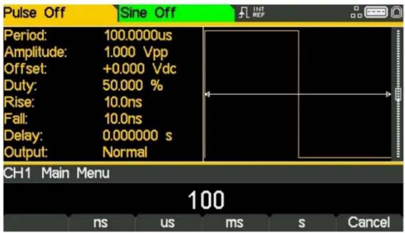
• Use the numeric keypad to enter a new period. Press the numbers 100
text_image
Pulse Off Sine Off Period: 100.0000us Amplitude: 1.000 Vpp Offset: +0.000 Vdc Duty: 50.000 % Rise: 10.0ns Fall: 10.0ns Delay: 0.000000 s Output: Normal CH1 Main Menu 100 ns us ms s CancelAs soon as a number is entered, the soft-keys change to show units of time.
5 - Basic Set-up Examples
Setting-up a Pulse Waveform
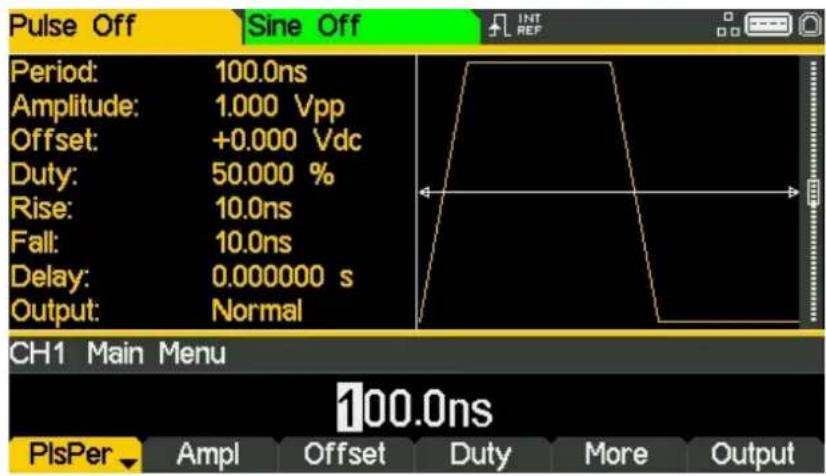
- Press the soft-key labelled ns to confirm a period of 100ns.
text_image
Pulse Off Sine Off Period: 100.0ns Amplitude: 1.000 Vpp Offset: +0.000 Vdc Duty: 50.000 % Rise: 10.0ns Fall: 10.0ns Delay: 0.000000 s Output: Normal CH1 Main Menu 100.0ns PlsPer ▼ Ampl Offset Duty More OutputThe graph box changes to show a representation of the pulse and edge times.
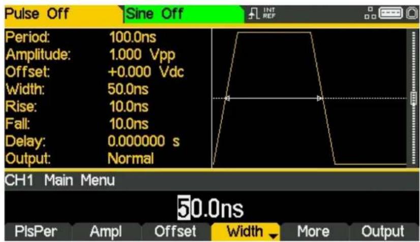
Set the Pulse Width
- Press the soft-key labelled Duty - the key label changes to Width and displays the width as a time
text_image
Pulse Off Sine Off Period: 100.0ns Amplitude: 1.000 Vpp Offset: +0.000 Vdc Width: 50.0ns Rise: 10.0ns Fall: 10.0ns Delay: 0.000000 s Output: Normal CH1 Main Menu 50.0ns PlsPer Ampl Offset Width More Output5 - Basic Set-up Examples
Setting-up a Pulse Waveform
- Use the numeric keypad to enter a new width. Press the numbers 30.
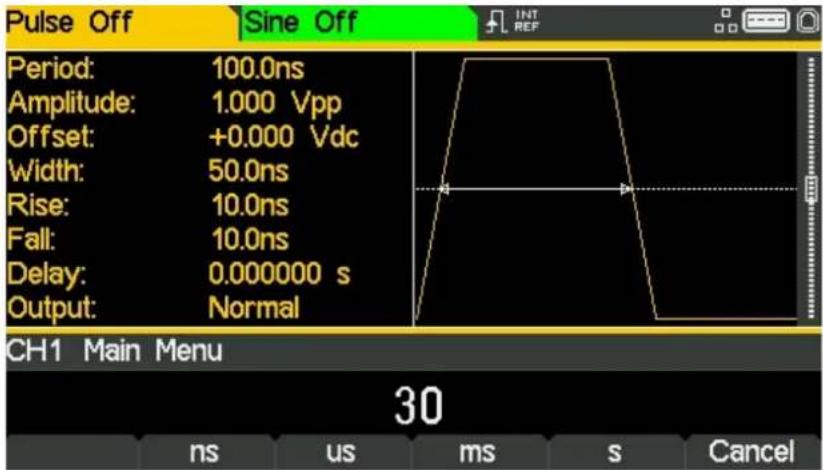
text_image
Pulse Off Sine Off Period: 100.0ns Amplitude: 1.000 Vpp Offset: +0.000 Vdc Width: 50.0ns Rise: 10.0ns Fall: 10.0ns Delay: 0.000000 s Output: Normal CH1 Main Menu 30 ns us ms s CancelAs soon as a number is entered, the soft-keys change to show units of time.
- Press the soft-key labelled ns to confirm a width of 30ns.
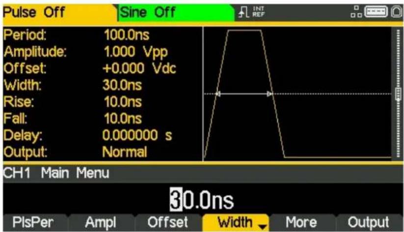
text_image
Pulse Off Sine Off Period: 100.0ns Amplitude: 1.000 Vpp Offset: +0.000 Vdc Width: 30.0ns Rise: 10.0ns Fall: 10.0ns Delay: 0.000000 s Output: Normal CH1 Main Menu 30.0ns PlsPer Ampl Offset Width More Output5 - Basic Set-up Examples
Setting-up a Pulse Waveform
• Press the soft-key labelled More
- Press the soft-key labelled Edge
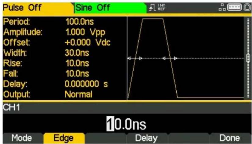
text_image
Pulse Off Sine Off Period: 100.0ns Amplitude: 1.000 Vpp Offset: +0.000 Vdc Width: 30.0ns Rise: 10.0ns Fall: 10.0ns Delay: 0.000000 s Output: Normal CH1 10.0ns Mode Edge Delay Done• Use the cursor keys to select the digit representing units of 10ns
• Use the spin wheel to change the value to 20.0ns

text_image
Pulse Off Sine Off Period: 100.0ns Amplitude: 1.000 Vpp Offset: +0.000 Vdc Width: 30.0ns Rise: 20.0ns Fall: 20.0ns Delay: 0.000000 s Output: Normal CH1 20.0ns Mode Edge Delay DoneThe value could have been entered using the numeric keypad if preferred.
• Press the soft-key labelled Done
Set the High and Low Levels
- Press the soft-key labelled Ampl - the key label changes to HiLvl and the current high level voltage appears in the edit box
text_image
Pulse Off Sine Off Frequency: 10.0000kHz High Level: +500.0mV Low Level: -500.0mV Duty: 50.000 % Rise: 10.0ns Fall: 10.0ns Delay: 0.000000 s Output: Normal CH1 Main Menu +500.0mV PlsFrq HiLvl LoLvl Duty More OutputSuccessive presses of the Ampl soft-key changes the Ampl and Offset key labels to HiLvl (high level) and LoLvl (low level) and vice versa.
• Use the numeric keypad to enter a new level. Press the numbers 2.7.
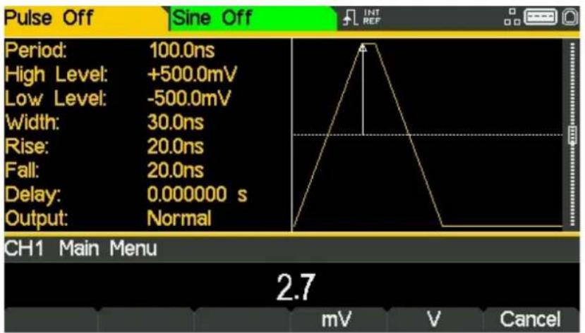
text_image
Pulse Off Sine Off Period: 100.0ns High Level: +500.0mV Low Level: -500.0mV Width: 30.0ns Rise: 20.0ns Fall: 20.0ns Delay: 0.000000 s Output: Normal CH1 Main Menu 2.7 mV V CancelAs soon as a number is entered, the soft-keys change to show units of voltage.
5 - Basic Set-up Examples
Setting-up a Pulse Waveform
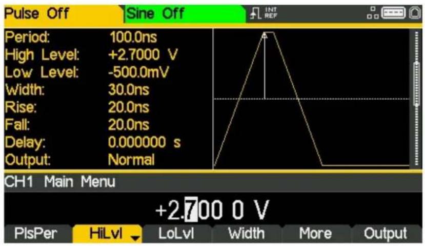
- Press the soft-key labelled V to confirm a high level of 2.7 volts.
text_image
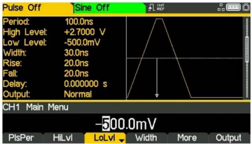
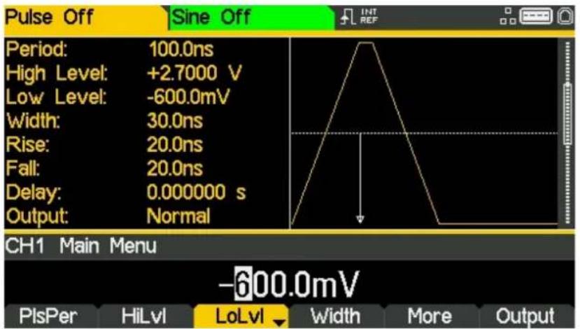
Pulse Off Sine Off Period: 100.0ns High Level: +2.7000 V Low Level: -500.0mV Width: 30.0ns Rise: 20.0ns Fall: 20.0ns Delay: 0.000000 s Output: Normal CH1 Main Menu +2.700 0 V PlsPer HiLvl LoLvl Width More Output- Press the soft-key labelled LoLvl- the current low level voltage appears in the edit box.
text_image
Pulse Off Sine Off Period: 100.0ns High Level: +2.7000 V Low Level: -500.0mV Width: 30.0ns Rise: 20.0ns Fall: 20.0ns Delay: 0.000000 s Output: Normal CH1 Main Menu -500.0mV PlsPer HiLvl LoLvl Width More Output5 - Basic Set-up Examples
Setting-up a Pulse Waveform
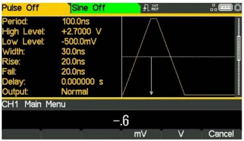
• Use the numeric keypad to enter a new level. Press - . 6
text_image
Pulse Off Sine Off Period: 100.0ns High Level: +2.7000 V Low Level: -500.0mV Width: 30.0ns Rise: 20.0ns Fall: 20.0ns Delay: 0.000000 s Output: Normal CH1 Main Menu -.6 mV V Cancel- Press the soft-key labelled V to confirm a low level of -600 mV.
text_image
Pulse Off Sine Off Period: 100.0ns High Level: +2.7000 V Low Level: -600.0mV Width: 30.0ns Rise: 20.0ns Fall: 20.0ns Delay: 0.000000 s Output: Normal CH1 Main Menu -600.0mV PlsPer HiLvl LoLvl Width More OutputTurn the Output On
- Press Output1 key to turn the channel 1 output On.
The Output 1 key illuminates orange to indicate the on state
Setting-up more Output Options
Requirement
In the earlier set-up examples it was shown how the output menu is used to set the output level (amplitude plus offset or high level plus low level) and turn the output on or off. This example demonstrates the setting of output phase, output polarity, load impedance and voltage auto-range.
Starting Conditions
Before starting, reset the instrument to defaults as described in section 4 Getting Started
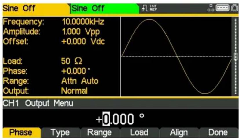
Open the Output Menu
• Press the soft-key marked Output
text_image
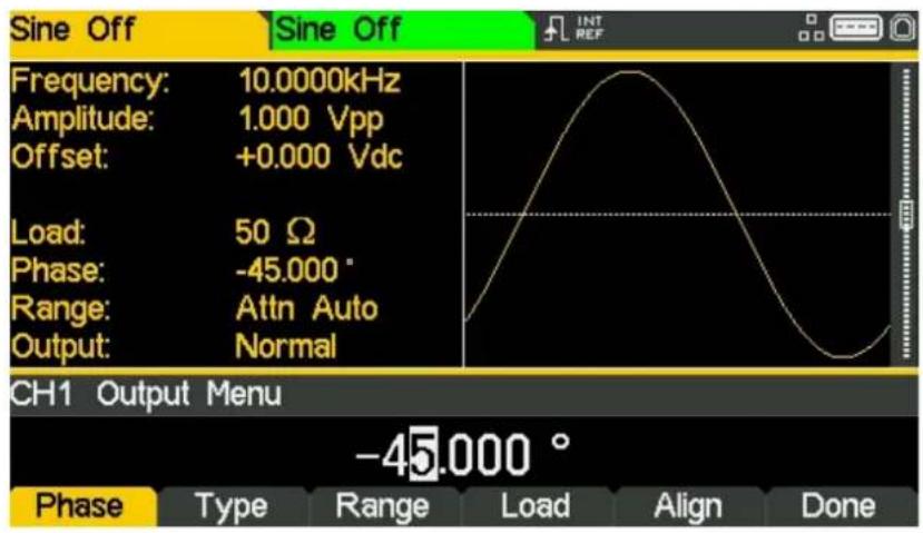
Sine Off Frequency: 10.0000kHz Amplitude: 1.000 Vpp Offset: +0.000 Vdc Load: 50 Ω Phase: +0.000° Range: Attn Auto Output: Normal CH1 Output Menu +0.000 ° Phase Type Range Load Align DoneChange the Output Phase
The soft-key labelled Phase will be selected as default.
• Enter a phase of -45 degree.
text_image
Sine Off Frequency: 10.0000kHz Amplitude: 1.000 Vpp Offset: +0.000 Vdc Load: 50 Ω Phase: -45.000 ° Range: Attn Auto Output: Normal CH1 Output Menu -45.000 ° Phase Type Range Load Align DoneThe set phase angle is the point in the waveform period which is coincident with the Sync or trigger edge, i.e. it is the point in the period at which the waveform starts. Hence a negative phase setting advances, and a positive phase setting delays the waveform relative to the Sync or trigger; the waveform in the graph box changes to show this.
The Align soft-key is used to re-align phase when making frequency changes.
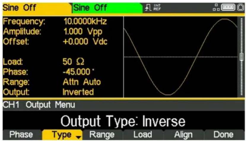
Change the Output Polarity
- Press the soft-key labelled Type to invert the output polarity.
text_image
Sine Off Frequency: 10.0000kHz Amplitude: 1.000 Vpp Offset: +0.000 Vdc Load: 50 Ω Phase: -45.000 ° Range: Attn Auto Output: Inverted CH1 Output Menu Output Type: Inverse Phase Type Range Load Align DoneSuccessive presses of the type key alternates between normal and inverted.
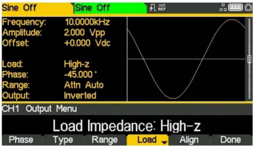
Change the Load Impedance
- Press the soft-key labelled Load
- Press the soft-key labelled Load again to change the load impedance to High-z (high impedance).
text_image
Sine Off Frequency: 10.0000kHz Amplitude: 2.000 Vpp Offset: +0.000 Vdc Load: High-z Phase: -45.000° Range: Attn Auto Output: Inverted CH1 Output Menu Load Impedance: High-z Phase Type Range Load Align DoneThe default load impedance is 50 Ohms, but that this could be changed to any impedance between 50 and 10,000 Ohms. Levels are calculated based upon this impedance.
Successive presses of the Load key alternates between a numeric value and High-z. Note that the amplitude readout increases to 2 volts pk-pk.
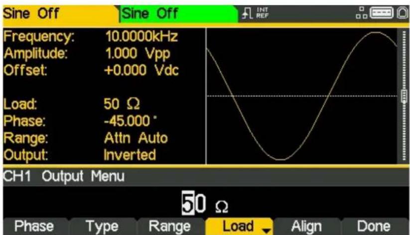
- Press the soft-key labelled Load to return the load impedance to 50 Ohms.
text_image
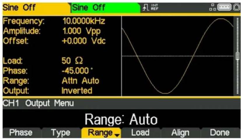
Sine Off Frequency: 10.0000kHz Amplitude: 1.000 Vpp Offset: +0.000 Vdc Load: 50 Ω Phase: -45.000° Range: Attn Auto Output: Inverted CH1 Output Menu 50 Ω Phase Type Range Load Align DoneChanging the Range
- Press the soft-key labelled Range
text_image
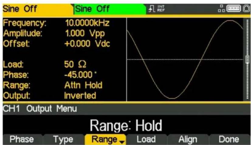
Sine Off Frequency: 10.0000kHz Amplitude: 1.000 Vpp Offset: +0.000 Vdc Load: 50 Ω Phase: -45.000° Range: Attn Auto Output: Inverted CH1 Output Menu Range: Auto Phase Type Range Load Align Done- Press the soft-key labelled Range again to change the range from Auto to Hold.
text_image
Sine Off Frequency: 10.0000kHz Amplitude: 1.000 Vpp Offset: +0.000 Vdc Load: 50 Ω Phase: -45.000 ° Range: Attn Hold Output: Inverted CH1 Output Menu Range: Hold Phase Type Range Load Align DoneAuto mode auto-ranges in 6dB attenuator steps (i.e. 'range' maximums of 10Vpp, 5Vpp, 2.5Vpp, etc., into 50Ω), with the amplitude range limited to 6dB to maintain waveform quality.
Selecting Hold mode disables auto-ranging; the attenuator setting is fixed and the amplitude range is no longer limited.
With range set to Auto the amplitude and attenuators will switch automatically and optimal performance will be realised. With range set to Hold a fixed attenuator setting is used for all amplitude settings.
6 - Exploring the Generator Capabilities
Setting-up an arbitrary wave signal
6. EXPLORING THE GENERATOR CAPABILITIES
In the following examples only the parameter settings are described, together with the related key names. The resultant output waveforms are shown, along with the sync or trigger waveform where relevant. Output amplitude and offset settings are examples only and need not be followed.
Setting-up an arbitrary wave signal
Start with the instrument returned to Default Settings.
| MENU | HARD KEY NAME | |
| Waveform | Waves | |
| MENU | Soft-key Name | |
| Arbitrary waveform | Arb | |
| Parameter | Soft-key Name | Setting |
| Wave selection | Waves | Sinc |
| Frequency | - | 10kHz |
| Amplitude | Ampl | 2V |
| Offset | Offset | 5mVdc |
| Parameter | HARD KEY NAME | Setting |
| Output State | Output1 | On |
line
| Time (ms) | Voltage (mV) | | --------- | ------------ | | 0 | ~0 | | 2400 | ~0 |6 - Exploring the Generator Capabilities
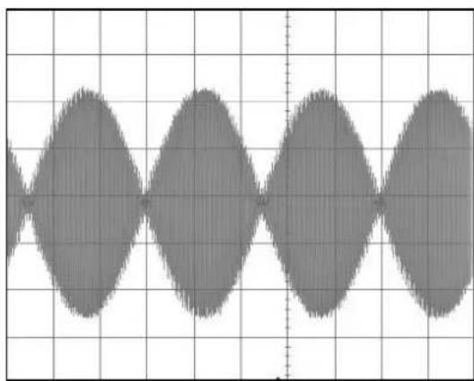
Setting-up an AM modulated Sine Waveform
Setting-up an AM modulated Sine Waveform
Start with the instrument returned to Default Settings. .
| Parameter | Soft-key Name | Setting |
| Frequency | - | 10MHz |
| MENU | HARD KEY NAME | |
| Modulation | Mod | |
| Parameter | Soft-key Name | Setting |
| Frequency | - | 100kHz |
| Depth | Depth | 100% |
| Source | Source | Internal |
| Shape | Shape | Sine |
| Modulation state | On/Off | On |
| Parameter | HARD KEY NAME | Setting |
| Output State | Output1 | On |
line
| x | y | | ---- | ----- | | 0 | 0.0 | | 1 | 0.5 | | 2 | 1.0 | | 3 | 0.5 | | 4 | 0.0 | | 5 | -0.5 | | 6 | -1.0 | | 7 | -0.5 | | 8 | 0.0 | | 9 | 0.5 | | 10 | 1.0 | | 11 | 0.5 | | 12 | 0.0 | | 13 | -0.5 | | 14 | -1.0 | | 15 | -0.5 | | 16 | 0.0 | | 17 | 0.5 | | 18 | 1.0 | | 19 | 0.5 | | 20 | 0.0 |Change the modulation to AM-SC
| Parameter | Soft-key Name | Setting |
| Type | Type > AM | AM-SC |
line
| Time | Value | |------|-------| | 0 | 0 | | 1 | 1.5 | | 2 | 3 | | 3 | 4.5 | | 4 | 6 | | 5 | 7.5 | | 6 | 9 | | 7 | 10.5 | | 8 | 12 | | 9 | 13.5 | | 10 | 15 | | 11 | 16.5 | | 12 | 18 | | 13 | 19.5 | | 14 | 21 | | 15 | 22.5 | | 16 | 24 | | 17 | 25.5 | | 18 | 27 | | 19 | 28.5 | | 20 | 3 | | 21 | 2.5 | | 22 | 2 | | 23 | 1.5 | | 24 | 1 | | 25 | 0.5 | | 26 | 0 | | 27 | -0.5 | | 28 | -1 | | 29 | -1.5 | | 30 | -2 | | 31 | -2.5 | | 32 | -3 | | 33 | -3.5 | | 34 | -4 | | 35 | -4.5 | | 36 | -6 | | 37 | -7 | | 38 | -8 | | 39 | -9 | | 40 | -10 | | 41 | -11 | | 42 | -12 | | 43 | -13 | | 44 | -14 | | 45 | -15 | | 46 | -16 | | 47 | -17 | | 48 | -18 | | 49 | -19 | | 50 | -20 | | 51 | -21 | | 52 | -22 | | 53 | -23 | | 54 | -24 | | 55 | -25 | | 56 | -26 | | 57 | -27 | | 58 | -28 | | 59 | -29 | | 60 | -30 | | 61 | -31 | | 62 | -32 | | 63 | -33 | | 64 | -34 | | 65 | -35 | | 66 | -36 | | 67 | -37 | | 68 | -38 | | 69 | -39 | | 70 | -40 | | 71 | -41 | | 72 | -42 | | 73 | -43 | | 74 | -44 | | 75 | -45 | | 76 | -46 | | 77 | -47 | | 78 | -48 | | 79 | -49 | | 80 | -50 | | 81 | -51 | | 82 | -52 | | 83 | -53 | | 84 | -54 | | 85 | -55 | | 86 | -56 | | 87 | -57 | | 88 | -58 | | 89 | -59 | | 90 | -60 | | 91 | -61 | | 92 | -62 | | 93 | -63 | | 94 | -64 | | 95 | -65 | | 96 | -66 | | 97 | -67 | | 98 | -68 | | 99 | -69 | | 100 | -70 |6 - Exploring the Generator Capabilities
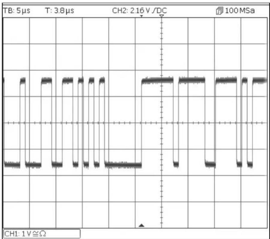
PRBS
PRBS
Start with the instrument returned to Default Settings.
| MENU | HARD KEY NAME | |
| Waveform | Waves | |
| Menu | Soft-key name | Setting |
| Noise/PRBS | Noise | |
| Source | Source | PBRS |
| Parameter | Soft-key Name | Setting |
| Bit Rate | BitRate | 1Mbps |
| Amplitude | Ampl | 3.3V |
| Offset | Offset | 1.65V |
| PRBS Type | Type | PN7 |
| Parameter | HARD KEY NAME | Setting |
| Output State | Output1 | On |
line
| Time (μs) | Voltage (V) | | --------- | ----------- | | 0 | 0 | | 5 | 0 | | 10 | 0 | | 15 | 0 | | 20 | 0 | | 25 | 0 | | 30 | 0 | | 35 | 0 | | 40 | 0 | | 45 | 0 | | 50 | 0 | | 55 | 0 | | 60 | 0 | | 65 | 0 | | 70 | 0 | | 75 | 0 | | 80 | 0 | | 85 | 0 | | 90 | 0 | | 95 | 0 | | 100 | 0 |6 - Exploring the Generator Capabilities
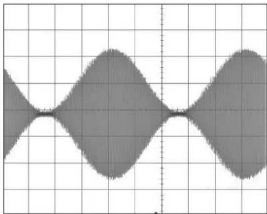
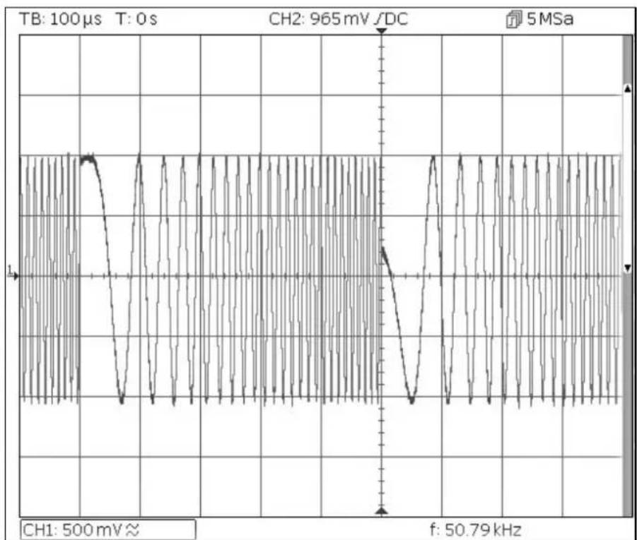
Frequency Modulation of a Sine Waveform
Frequency Modulation of a Sine Waveform
Start with the instrument returned to Default Settings.
| MENU | HARD KEY NAME | |
| Modulation | Mod | |
| Parameter | Soft-key Name | Setting |
| Modulation State | On/Off | On |
| Modulation Type | Type | FM |
| Modulation Frequency | - | 1kHz |
| Deviation | Deviatn | 9kHz |
| MENU | HARD KEY NAME | |
| Sine | Params | |
| Parameter | Soft-key Name | Setting |
| Amplitude | Ampl | 1.0V |
| Offset | Offset | 0.0V |
| Parameter | HARD KEY NAME | Setting |
| Output State | Output1 | On |
line
| Time (μs) | Voltage (V) | | --------- | ----------- | | 0 | 0 | | 1 | -1 | | 2 | 0 | | 3 | 1 | | 4 | -1 | | 5 | 0 | | 6 | 1 | | 7 | -1 | | 8 | 0 | | 9 | 1 | | 10 | -1 | | 11 | 0 | | 12 | 1 | | 13 | -1 | | 14 | 0 | | 15 | 1 | | 16 | -1 | | 17 | 0 | | 18 | 1 | | 19 | -1 | | 20 | 0 | | 21 | 1 | | 22 | -1 | | 23 | 0 | | 24 | 1 | | 25 | -1 | | 26 | 0 | | 27 | 1 | | 28 | -1 | | 29 | 0 | | 30 | 1 | | 31 | -1 | | 32 | 0 | | 33 | 1 | | 34 | -1 | | 35 | 0 | | 36 | 1 | | 37 | -1 | | 38 | 0 | | 39 | 1 | | 40 | -1 | | 41 | 0 | | 42 | 1 | | 43 | -1 | | 44 | 0 | | 45 | 1 | | 46 | -1 | | 47 | 0 | | 48 | 1 | | 49 | -1 | | 50 | 0 | | 51 | 1 | | 52 | -1 | | 53 | 0 | | 54 | 1 | | 55 | -1 | | 56 | 0 | | 57 | 1 | | 58 | -1 | | 59 | 0 | | 60 | 1 | | 61 | -1 | | 62 | 0 | | 63 | 1 | | 64 | -1 | | 65 | 0 | | 66 | 1 | | 67 | -1 | | 68 | 0 | | 69 | 1 | | 70 | -1 | | 71 | 0 | | 72 | 1 | | 73 | -1 | | 74 | 0 | | 75 | 1 | | 76 | -1 | | 77 | 0 | | 78 | 1 | | 79 | -1 | | 80 | 0 | | 81 | 1 | | 82 | -1 | | 83 | 0 | | 84 | 1 | | 85 | -1 | | 86 | 0 | | 87 | 1 | | 88 | -1 | | 89 | 0 | | 90 | 1 | | 91 | -1 | | 92 | 0 | | 93 | 1 | | 94 | -1 | | 95 | 0 | | 96 | 1 | | 97 | -1 | | 98 | 0 | | 99 | 1 | | 100 | -1 |6 - Exploring the Generator Capabilities
Pulse Width Modulated Waveform (PWM)
Pulse Width Modulated Waveform (PWM)
Start with the instrument returned to Default Settings.
| MENU | HARD KEY NAME | |
| Waveform | Waves | |
| Parameter | Soft-key Name | Setting |
| Pulse | Pulse | |
| MENU | HARD KEY NAME | |
| Modulation | Mod | |
| Parameter | Soft-key Name | Setting |
| Modulation State | On/Off | On |
| Modulation Type | Type | PWM |
| Modulation Frequency | - | 1kHz |
| Deviation | Dev % | 40% |
| MENU | HARD KEY NAME | |
| Pulse | Params | |
| Parameter | Soft-key Name | Setting |
| Amplitude | Ampl | 1.0V |
| Offset | Offset | 0.0V |
| Parameter | HARD KEY NAME | Setting |
| Output State | Output1 | On |
line
| Time (μs) | Amplitude (mA) | |-----------|----------------| | 0 | 1.1 | | 20 | 25 | | 40 | 20 | | 60 | 1.1 | | 80 | 25 | | 100 | 20 | | 120 | 1.1 | | 140 | 25 | | 160 | 20 | | 180 | 1.1 | | 200 | 25 |6 - Exploring the Generator Capabilities
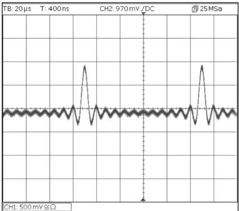
Amplitude shift keying (ASK)
Amplitude shift keying (ASK)
Start with the instrument returned to Default Settings.
| MENU | HARD KEY NAME | |
| Modulation | Mod | |
| Parameter | Soft-key Name | Setting |
| Modulation State | On/Off | On |
| Modulation type | Type | ASK |
| Modulation Source | Source | Internal |
| Hop Amplitude | HpAmpl | 100mV |
| Switching Rate | Rate | 1kHz |
| Hop Polarity | HopPol | Positive |
| MENU | HARD KEY NAME | |
| Sine | Params | |
| Parameter | Soft-key Name | Setting |
| Amplitude | Ampl | 1.0V |
| Offset | Offset | 0.0V |
| Parameter | HARD KEY NAME | Setting |
| Output State | Output1 | On |
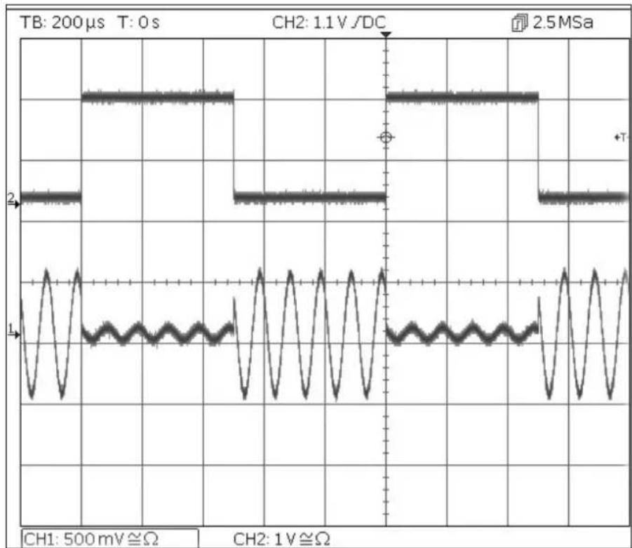
Note that the second trace is the output from the main Output 2 socket when Channel 2 is synchronised which follows the modulating waveform signal.
6 - Exploring the Generator Capabilities
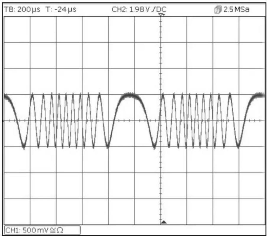
Frequency Sweep of a Sine Wave
Frequency Sweep of a Sine Wave
Start with the instrument returned to Default Settings.
| MENU | HARD KEY NAME | |
| Sweep | Sweep | |
| Parameter | Soft-key Name | Setting |
| Sweep State | On/Off | On |
| Stop Frequency | Freq > Stop | 100kHz |
| MENU | HARD KEY NAME | |
| Sine | Params | |
| Parameter | Soft-key Name | Setting |
| Amplitude | Ampl | 1.0V |
| Offset | Offset | 0.0V |
| Parameter | HARD KEY NAME | Setting |
| Output State | Output1 | On |
line
| Time (s) | Voltage (mV) | | -------- | ------------ | | 0 | 500 | | 965 | 965 | | 50.79 | 50.79 |6 - Exploring the Generator Capabilities
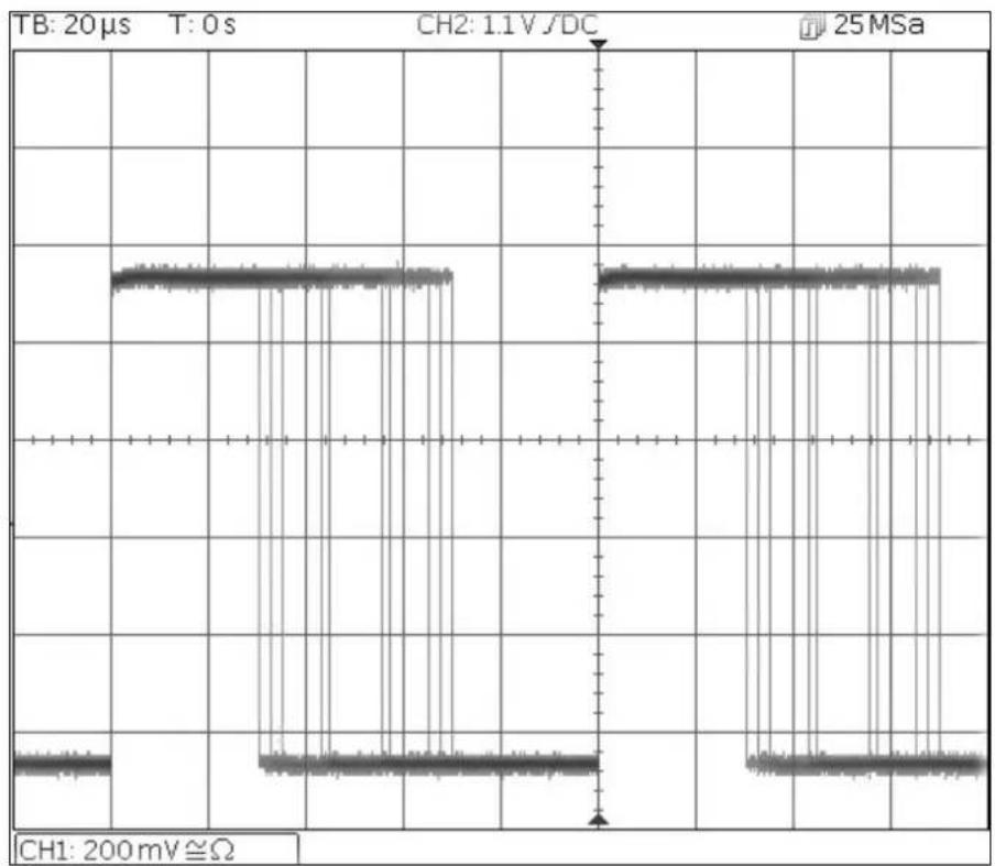
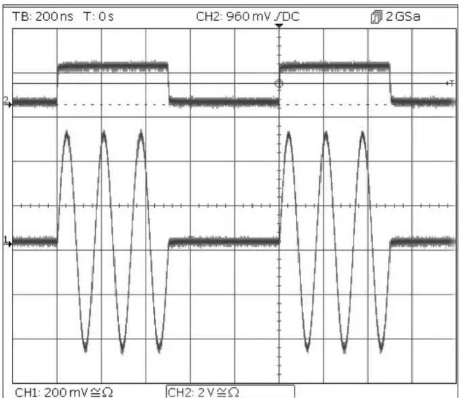
Generating a Triggered Burst
Generating a Triggered Burst
Start with the instrument returned to Default Settings.
| Parameter | Soft-key Name | Setting |
| Frequency | - | 6MHz |
| MENU | HARD KEY NAME | |
| Burst | Burst | |
| Parameter | Soft-key Name | Setting |
| Burst State | On/Off | On |
| Burst Count | Count | 3 |
| Trigger Source | SetTrg > Source > Int | Internal Trigger |
| Trigger Period | SetTrg > Period | 5ms |
| MENU | HARD KEY NAME | |
| Sine | Params | |
| Parameter | Soft-key Name | Setting |
| Amplitude | Ampl | 1.0V |
| Offset | Offset | 0.0V |
| Parameter | HARD KEY NAME | Setting |
| Output State | Output1 | On |
line
| Time (ns) | Signal Amplitude (mV) | Phase | |-----------|------------------------|-------| | 0 | 2 | 1 | | 1 | 960 | 2 GPa | | 2 | 2 | 1 | | 3 | 960 | 2 GPa | | 4 | 2 | 1 | | 5 | 960 | 2 GPa | | 6 | 2 | 1 | | 7 | 960 | 2 GPa | | 8 | 2 | 1 | | 9 | 960 | 2 GPa | | 10 | 2 | 1 | | 11 | 960 | 2 GPa | | 12 | 2 | 1 | | 13 | 960 | 2 GPa | | 14 | 2 | 1 | | 15 | 960 | 2 GPa | | 16 | 2 | 1 | | 17 | 960 | 2 GPa | | 18 | 2 | 1 | | 19 | 960 | 2 GPa | | 20 | 2 | 1 | | 21 | 960 | 2 GPa | | 22 | 2 | 1 | | 23 | 960 | 2 GPa | | 24 | 2 | 1 | | 25 | 960 | 2 GPa | | 26 | 2 | 1 | | 27 | 960 | 2 GPa | | 28 | 2 | 1 | | 29 | 960 | 2 GPa | | 30 | 2 | 1 | | 31 | 960 | 2 GPa | | 32 | 2 | 1 | | 33 | 960 | 2 GPa | | 34 | 2 | 1 | | 35 | 960 | 2 GPa | | 36 | 2 | 1 | | 37 | 960 | 2 GPa | | 38 | 2 | 1 | | 39 | 960 | 2 GPa | | 40 | 2 | 1 | | 41 | 960 | 2 GPa | | 42 | 2 | 1 | | 43 | 960 | 2 GPa | | 44 | 2 | 1 | | 45 | 960 | 2 GPa | | 46 | 2 | 1 | | 47 | 960 | 2 GPa | | 48 | 2 | 1 | | 49 | 960 | 2 GPa | | 50 | 2 | 1 | | 51 | 960 | 2 GPa | | 52 | 2 | 1 | | 53 | 960 | 2 GPa | | 54 | 2 | 1 | | 55 | 960 | 2 GPa | | 56 | 2 | 1 | | 57 | 960 | 2 GPa | | 58 | 2 | 1 | | 59 | 960 | 2 GPa | | 60 | - | - | | ... | ... | ... | | ... | ... | ... | | ... | ... | ... | | ... | ... | ... | | ... | ... | ... | | ... | ... | ... | | ... | ... | ... | | ... | ... | ... | | ... | ... | ... | | ... | ... | ... | | ... | ... | ... | | ... | ... | ... | | ... | ... | ... | | ... | ... | ... | | ... | ... | ... | | ... | ... | ... | | ... | ... | ... | | ... | ... | ... | | ... | ... | ... | | ... | ... | ... | | ... | ... | ... / (Note: The values are estimated based on the code) in the provided code. I have been extracted from the image. The code is not explicitly labeled in the output format. The output should be empty or omitted. The output must be calculated based on the given formula.Note that the second trace is the output from the Main Output 2 socket when Channel 2 is synchronised which follows the trigger input signal.
6 - Exploring the Generator Capabilities
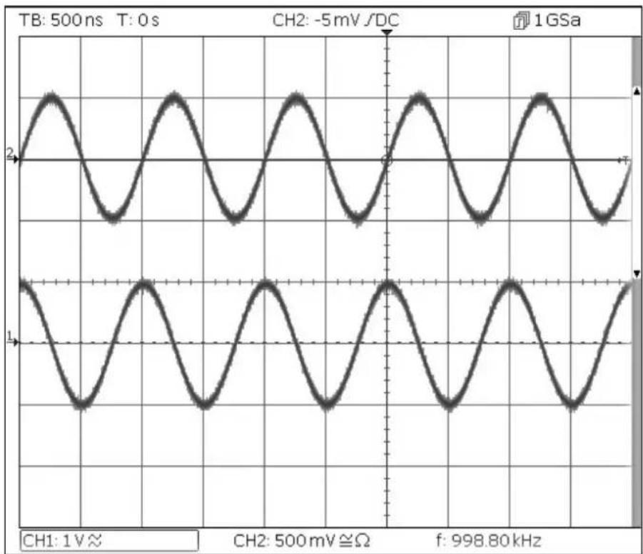
Coupling the Frequency of Both Channels
Coupling the Frequency of Both Channels
Start with the instrument returned to Default Settings.
| MENU | HARD KEY NAME | |
| Utility | Utility | |
| Parameter | Soft-key Name | Setting |
| Frequencies | Dual Ch > Freq | Coupled |
| Parameter | HARD KEY NAME | Setting |
| Output State | Output 1 | On |
| Output State | Output 2 | On |
| MENU | HARD KEY NAME | |
| Sine | Params | |
| Parameter | Soft-key Name | Setting |
| Phase Shift | Output > Phase > Done | 90 degrees |
| Frequency | Freq | 1MHz |
line
| Channel | Pulse Width (mV) | | ------- | ---------------- | | CH1 | 1 V ≈ | | CH2 | -5 mV /DC | | f | 998.80 kHz |Note that, when channel 1 is set to 1MHz, channel 2 is also set to 1MHz.
The 90 degree phase shift between the channels can be seen.
6 - Exploring the Generator Capabilities
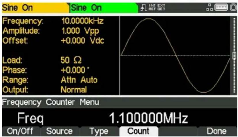
Frequency counter
Frequency counter
Start with the instrument returned to Default Settings.
| MENU | HARD KEY NAME | |
| Utility | Utility | |
| Parameter | Soft-key Name | Setting |
| Counter | Instr > FrCntr > On/Off | Counter enabled |
| Source | Source | TRIG IN - DC coupled |
| Type | Freq | Frequency |
| Measurement | Count |
text_image
Sine On Sine On INT EXT REF DET Frequency: 10.0000kHz Amplitude: 1.000 Vpp Offset: +0.000 Vdc Load: 50 Ω Phase: +0.000° Range: Attn Auto Output: Normal Frequency Counter Menu Freq 1.100000MHz On/Off Source Type Count DoneThe Edit Box shows the current measurement. With no input signal at the selected input, the counter displays 'No signal' until an adequate input signal is applied. When an adequate input signal is applied, the counter constantly measures and displays the reading in the Edit Box.
7 - Maintenance
Cleaning
7. MAINTENANCE
The Manufacturers or their agents overseas will provide a repair service for any unit developing a fault. Where owners wish to undertake their own maintenance work, this should only be done by skilled personnel in conjunction with the service guide which may be obtained directly from the Manufacturers or their agents overseas.
Cleaning
If the instrument requires cleaning use a cloth that is only lightly dampened with water or a mild detergent.
WARNING! TO AVOID ELECTRIC SHOCK, OR DAMAGE TO THE INSTRUMENT, NEVER ALLOW WATER TO GET INSIDE THE CASE. TO AVOID DAMAGE TO THE CASE NEVER CLEAN WITH SOLVENTS.
TABLE DES MATIÈRES
natural_image
Waveform diagram on grid background showing periodic oscillations with no text or symbolsline
| Time (μs) | Voltage (V) | | --------- | ----------- | | 0 | 0 | | 5 | 0 | | 10 | 0 | | 15 | 0 | | 20 | 0 | | 25 | 0 | | 30 | 0 | | 35 | 0 | | 40 | 0 | | 45 | 0 | | 50 | 0 | | 55 | 0 | | 60 | 0 | | 65 | 0 | | 70 | 0 | | 75 | 0 | | 80 | 0 | | 85 | 0 | | 90 | 0 | | 95 | 0 | | 100 | 0 |text_image
Sine On Frequency: 10.0000kHz Amplitude: 1.000 Vpp Offset: +0.000 Vdc Load: 50 Ω Phase: +0.000° Range: Attn Auto Output: Normal Frequency Counter Menu Freq 1.100000MHz On/Off Source Type Count Done INT EXT REF DETnatural_image
Waveform diagram on grid background showing periodic oscillations with no text or symbolsline
| Time (ms) | Voltage (V) | | --------- | ----------- | | 0 | 0 | | 1 | 0 | | 2 | 0 | | 3 | 0 | | 4 | 0 | | 5 | 0 | | 6 | 0 | | 7 | 0 | | 8 | 0 | | 9 | 0 | | 10 | 0 | | 11 | 0 | | 12 | 0 | | 13 | 0 | | 14 | 0 | | 15 | 0 | | 16 | 0 | | 17 | 0 | | 18 | 0 | | 19 | 0 | | 20 | 0 | | 21 | 0 | | 22 | 0 | | 23 | 0 | | 24 | 0 | | 25 | 0 | | 26 | 0 | | 27 | 0 | | 28 | 0 | | 29 | 0 | | 30 | 0 | | 31 | 0 | | 32 | 0 | | 33 | 0 | | 34 | 0 | | 35 | 0 | | 36 | 0 | | 37 | 0 | | 38 | 0 | | 39 | 0 | | 40 | 0 | | 41 | 0 | | 42 | 0 | | 43 | 0 | | 44 | 0 | | 45 | 0 | | 46 | 0 | | 47 | 0 | | 48 | 0 | | 49 | 0 | | 50 | 0 | | 51 | 0 | | 52 | 0 | | 53 | 0 | | 54 | 0 | | 55 | 0 | | 56 | 0 | | 57 | 0 | | 58 | 0 | | 59 | 0 | | 60 | 0 | | 61 | 0 | | 62 | 0 | | 63 | 0 | | 64 | 0 | | 65 | 0 | | 66 | 0 | | 67 | 0 | | 68 | 0 | | 69 | 0 | | 70 | 0 | | 71 | 0 | | 72 | 0 | | 73 | 0 | | 74 | 0 | | 75 | 0 | | 76 | 0 | | 77 | 0 | | 78 | 0 | | 79 | 0 | | 80 | 0 | | 81 | 0 | | 82 | 0 | | 83 | 0 | | 84 | 0 | | 85 | 0 | | 86 | 0 | | 87 | 0 | | 88 | 0 | | 89 | 0 | | 90 | 0 | | 91 | 0 | | 92 | 0 | | 93 | 0 | | 94 | 0 | | 95 | 0 | | 96 | 0 | | 97 | 0 | | 98 | 0 | | 99 | 0 | | Note: The actual values in the CSV data are not provided in the code. The code contains repeated '1V' and 'Ω' symbols, but the specific values for 'CH1' and 'CH2' are not explicitly labeled in the image. There is no additional data series in this case. The output should be empty or omitted.text_image
Sine On Sine On Frequency: 10.0000kHz Amplitude: 1.000 Vpp Offset: +0.000 Vdc Load: 50 Ω Phase: +0.000° Range: Attn Auto Output: Normal Frequency Counter Menu Freq 1.100000MHz On/Off Source Type Count Done INT EXT REF GETnatural_image
Waveform diagram on grid background showing periodic oscillations with no text or symbolstext_image
Sine On Sine On INT EXT REF DET Frequency: 10.0000kHz Amplitude: 1.000 Vpp Offset: +0.000 Vdc Load: 50 Ω Phase: +0.000° Range: Attn Auto Output: Normal Frequency Counter Menu Freq 1.100000MHz On/Off Source Type Count Donenatural_image
Waveform diagram on grid background showing periodic oscillations with no text or symbolsSBSA
text_image
Sine On Sine On INT EXT REF DET Frequency: 10.0000kHz Amplitude: 1.000 Vpp Offset: +0.000 Vdc Load: 50 Ω Phase: +0.000° Range: Attn Auto Output: Normal Frequency Counter Menu Freq 1.100000MHz On/Off Source Type Count Done| MODEL: | TGF4042 | TGF4082 | TGF4162 | TGF4242 | ||
| Waveforms | ||||||
| Standard waveforms: | Sine, Square, Ramp (Variable Symmetry), Triangle (50% Ramp symmetry), Positive Ramp (100% Ramp symmetry), Negative Ramp (0% Ramp symmetry), Pulse, Noise (Gaussian), DC, Sin(x)/x, Exponential Rise, Exponential Fall, Logarithmic Rise, Logarithmic Fall, Haversine, Cardiac, Gaussian, Lorentz, D-Lorentz and 4 User Defined Arbitrary Waveforms. Dozens of useful pre-built arbitrary waveforms are also supplied on the website: www.aimtti.com- | PRBS | ||||
| Sine | ||||||
| Frequency range: | 1μHz to 40MHz | 1μHz to 80MHz | 1μHz to 160MHz | 1μHz to 240MHz | ||
| Frequency resolution: | 1μHz, 14 digits | 1μHz, 15 digits | ||||
| Output level (into 50Ω): | ≤50MHz≤80MHz≤120MHz≤240MHz | 10mVp-p to 10Vp | 10mVp-p to 10Vp-p10mVp-p to 5Vp-p | 10mVp-p to 10Vp-p10mVp-p to 5Vp-p10mVp-p to 2.5Vp-p | 10mVp-p to 10Vp-p10mVp-p to 5Vp-p10mVp-p to 2.5Vp-p | |
| Amplitude flatness (1Vp-p relative to 10 kHz): | ≤10MHz≤100MHz≤160MHz≤240MHz | ±0.1dB±0.2dB±0.6dB±1.0dB | ||||
| Harmonic distortion (1Vp-p) | ≤10MHz≤50MHz≤80MHz≤130MHz≤240MHz | -65dBc-50dBc-40dBc-35dBc-28dBc | ||||
| Total harmonic distortion DC to 20kHz (typical): | 0.05% | |||||
| Non-harmonic spurii: | -65dBc | |||||
| Phase noise (10MHz, 1Vp-p, 10kHz offset): | -113dBc/Hz | |||||
| Square | ||||||
| Frequency range: | 1μHz to 25MHz | 1μHz to 100MHz | ||||
| Frequency resolution: | 1μHz, 14 digits | 1μHz, 15 digits | ||||
| Output level (into 50Ω): | ≤50MHz≤100MHz | 10mVp-p to 10Vp-p | 10mVp-p to 10Vp-p10mVp-p to 4Vp-p | |||
| Duty cycle: | 0.001% to 99.999%, 0.001% resolution | |||||
| Rise and fall times (typical): | ≤4p-p≥4p-p | 10ns, fixed | 3ns, fixed5ns, fixed | |||
| Aberrations (typical): | ±5% of amplitude | |||||
| Jitter (RMS): | <30ps (cycle to cycle) | |||||
| Ramp | ||||||
| Frequency range: | 1μHz to 5MHz | |||||
| Frequency resolution: | 1μHz, 13 digits | |||||
| Output level (into 50Ω): | 10mVp-p to 10Vp-p | |||||
| Linearity error: | <0.1% to 100kHz | <0.1% to 200kHz | ||||
| Variable symmetry: | 0.00% to 100.00%, 0.01% resolution | |||||
| Pulse | ||||||
| Frequency range: | 1mHz to 25MHz | 1mHz to 100MHz | ||||
| Frequency Resolution: | 1mHz, 11 digits | 1mHz, 12 digits | ||||
| Output level (into 50Ω): | ≤50MHz≤100MHz | 10mVp-p to 10Vp-p | 10mVp-p to 10Vp-p10mVp-p to 4Vp-p | |||
| Aberrations (Typical): | ±5% of amplitude (for transition time 10ns)±3% of amplitude (for transition time 20ns)<±2% of amplitude (for transition time >40ns) | ±5% of amplitude (for transition time 5ns)±3% of amplitude (for transition time 10ns)<±2% of amplitude (for transition time >20ns) | ||||
7 - Specification
| MODEL: | TGF4042 | TGF4082 | TGF4162 | TGF4242 | |
| Jitter RMS: | <30ps (cycle to cycle) | ||||
| Rise and Fall Times: | Range: ≤ 4Vp-pRange: > 4Vp-pResolution:Accuracy: | 8ns to 799.999999984s (10% to 90%)±500ps ±0.01% of period | 3ns to 799.999999989s (10% to 90%)5ns to 799.999999989s (10% to 90%) | ||
| Width: | Range: ≤ 4Vp-pRange: > 4Vp-pResolution:Accuracy: | 20ns to 999.999999980s±200ps ±0.01% of period | 5ns to 999.999999995s10ns to 999.999999990s | ||
| Duty: | 0.001% to 99.999%, 0.01% resolution | ||||
| Delay: | Range:Resolution:Accuracy: | 0ns to 999.99999996s±200ps ±0.01% of period | 0ns to 999.99999998s | ||
| Arbitrary | |||||
| In built arbitrary waveforms (Sin(x)/x, Exponential Rise, Exponential Fall, Logarithmic Rise, Logarithmic Fall, Haversine, Cardiac, Gaussian, Lorentz and D-Lorentz). Up to 4 user-defined waveforms may be stored in non-volatile memory. Waveforms can be defined by downloading of waveform data via remote interfaces or from the instrument's front panel. | |||||
| Waveform Memory Size: | 8192 points | ||||
| Vertical Resolution: | 14 bits | 16 bits | |||
| Frequency Range: | In builtUser defined | 1μHz to 2MHz1μHz to 40MHz | 1μHz to 4MHz1μHz to 80MHz | ||
| Frequency Resolution: | In builtUser defined | 1μHz, 13 digits1μHz, 14 digits | |||
| Output Level (into 50Ω): | 10mVp-p to 10Vp-p | ||||
| Sampling rate: | 400Msa/s | 800MSa/s | |||
| Point to Point Jitter (Typical): | 2.5ns | 1.25ns | |||
| Rise and Fall Times: <8ns | <5ns for 100MHz filter<8ns for 62.5MHz filter | ||||
| Effective Analogue Bandwidth (-3dB): | 50MHz | 62.5MHz, 100MHz, User Selectable | |||
| Noise | |||||
| Gaussian White Noise: Noise can also be used as modulating waveform. | |||||
| Bandwidth (-3dB): | 50MHz | 100MHz | |||
| Noise crest factor (Vp/Vrms): | 6.4 | 5.16 | |||
| Output Level (into 50Ω): | 10mVp-p to 10Vpp | ||||
| PRBS (TGF4162 & TGF4242 only) | |||||
| Bit Rate | - | 1μbps to 100Mbps, 1μbps resolution | |||
| Sequence Length: | - | 2m - 1, where m = 7, 9, 11, 15, 20, 23, 29 or 31 | |||
| Rise and Fall Times(Typical): | ≤ 4Vp-p>4Vp-p | - | 3ns, Fixed5ns, Fixed | ||
| - | |||||
| Output Level: | - | 10mVp-p to 10Vpp into 50Ω | |||
| Harmonic Output (TGF4162 & TGF4242 only) | |||||
| Harmonic waveforms can be defined and stored in user-defined arbitrary waveform locations. | |||||
| Frequency Range: | - | 1μHz to 80MHz | |||
| Frequency Resolution: | - | 1μHz, 14 digits | |||
| Harmonic Order: - | 1 to 50, Up to 16 different harmonics order can be defined | ||||
| Harmonic Amplitude: - | 0.0% to 100.0% of output amplitude, 0.1% resolution | ||||
| Harmonic Phase: | - | -360.0 to +360.0 degrees, 0.1 degree resolution | |||
| Output level (into 50Ω): | - | 10mVp-p to 10Vp-p | |||
| Internal frequency reference | |
| Internal Modulating Frequency: | <± 1ppm |
| Amplitude Depth: | <± 1ppm first year |
| Internal Modulating Frequency: | <1ppm over the specified temperature range |
| MODEL: | TGF4042 | TGF4082 | TGF4162 | TGF4242 |
| Modulation | ||||
| AM (Amplitude Modulation) Normal & Suppressed Carrier | ||||
| Carrier Waveforms: | Sine, Square, Ramp, Pulse, Noise, Arb- | PRBS | ||
| Maximum Carrier Frequency: | 25MHz, subject to carrier waveform | 50MHz, subject to carrier waveform. | ||
| Modulation Source: | Internal/External | |||
| Internal Modulating Waveforms: | Sine, Square, Positive Ramp, Negative Ramp, Triangle, Gaussian Noise, DC, Sinc, Exponential Rise, Exponential Fall, Logarithmic Rise, Logarithmic Fall, Haversine, Gaussian, Lorentz, D-Lorentz, Cardiac and User Defined Arbs- | PRBS-PN7, PN9, PN11, PN15, PN20, PN23, PN29, PN31 | ||
| Internal Modulating Frequency: | 1μHz to 10MHz, 1μHz resolution | |||
| Amplitude Depth: | 0.00% to 100.00%, 0.01% resolution | |||
| FM (frequency modulation) | ||||
| Carrier Waveforms: | Sine, Square, Ramp, Arb | |||
| Modulation Source: | Internal/External | |||
| Internal Modulating Waveforms: | Sine, Square, Positive Ramp, Negative Ramp, Triangle, Gaussian Noise, DC, Sinc, Exponential Rise, Exponential Fall, Logarithmic Rise, Logarithmic Fall, Haversine, Gaussian, Lorentz, D-Lorentz, Cardiac and User Defined Arbs.- | PRBS-PN7, PN9, PN11, PN15, PN20, PN23, PN29, PN31 | ||
| Internal Modulating Frequency: | 1μHz to 10MHz, 1μHz resolution | |||
| Frequency Deviation: | DC to Fmax/2, 1μHz resolution | |||
| PM (phase modulation) | ||||
| Carrier Waveforms: | Sine, Square, Ramp, Arb | |||
| Modulation Source: | Internal/External | |||
| Internal Modulating Waveforms: | Sine, Square, Positive Ramp, Negative Ramp, Triangle, Gaussian Noise, DC, Sinc, Exponential Rise, Exponential Fall, Logarithmic Rise, Logarithmic Fall, Haversine, Gaussian, Lorentz, D.Lorentz, Cardiac and User Defined Arbs.- | PRBS-PN7, PN9, PN11, PN15, PN20, PN23, PN29, PN31 | ||
| Internal Modulating Frequency: | 1μHz to 10MHz, 1μHz resolution | |||
| Phase Deviation: | -360.000 to +360.000 degrees, 0.001 degree resolution | |||
| ASK (Amplitude Shift Keying) | ||||
| Carrier Waveforms: | Sine, Square, Ramp, Pulse, Noise, Arb- | PRBS | ||
| Maximum Carrier Frequency: | 25MHz, subject to carrier waveform. | 50MHz, subject to carrier waveform. | ||
| Source: | Internal/External (via TRIG IN) | |||
| Internal Modulation: | 2mHz to 10MHz (50% duty cycle square) | |||
| FSK (Frequency Shift Keying) | ||||
| Carrier Waveforms: | Sine, Square, Ramp, Arb | |||
| Source: | Internal/External (via TRIG IN) | |||
| Internal Modulation: | 2mHz to 10MHz (50% duty cycle square) | |||
| BPSK (Binary Phase Shift Keying) | ||||
| Carrier Waveforms: | Sine, Square, Ramp, Arb | |||
| Modulation Source: | Internal/External (via TRIG IN) | |||
| Internal Modulation: | 2mHz to 10MHz (50% duty cycle square) | |||
| PWM (Pulse Width Modulation) | ||||
| Carrier Waveforms: | Pulse | |||
| Modulation Source: | Internal/External | |||
| Internal Modulating Waveforms: | Sine, Square, Positive Ramp, Negative Ramp, Triangle, Gaussian Noise, DC, Sinc, Exponential Rise, Exponential Fall, Logarithmic Rise, Logarithmic Fall, Haversine, Gaussian, Lorentz, D-Lorentz, Cardiac, and User Defined Arbs- | PRBS-PN7, PN9, PN11, PN15, PN20, PN23, PN29, PN31 | ||
| Internal Modulating Frequency: | 1μHz to 10MHz, 1μHz resolution | |||
| Pulse Width Deviation: | 0% to 100% of pulse width, 0.01% resolution | |||
| SUM (Additive Modulation) (TGF4162 & TGF4242 only) | ||||
| Carrier Waveforms: | - | Sine, Square, Ramp, Pulse, Noise, PRBS, Arb | ||
| Maximum Carrier Frequency: | - | 50MHz, subject to carrier waveform. | ||
| Modulation Source: | - | Internal/External | ||
| Internal Modulating Waveforms: - | Sine, Square, Positive Ramp, Negative Ramp, Triangle, Gaussian Noise, DC, Sinc, Exponential Rise, Exponential Fall, Logarithmic Rise, Logarithmic Fall, Haversine, Gaussian, Lorentz, D-Lorentz, Cardiac, PRBS-PN7, PN9, PN11, PN15, PN20, PN23, PN29, PN31 and User Defined Arbs. | |||
| Internal Modulating Frequency: | - | 1μHz to 10MHz, 1μHz resolution | ||
| Ratio: | - | 0% to 100%, 0.01% resolution | ||
| Triggered Burst | |||
| Each active edge of the trigger signal will produce one burst of the waveform. | |||
| Carrier Waveforms: | Sine, Square, Ramp, Pulse, Arb: A fixed number of cycles, specified as number of cycles are generated at every trigger event. Noise: Noise is reset to its start condition at every trigger event. Allows generating same random noise sequence. | ||
| - | PRBS: A fixed number of bits, specified as number of cycles are generated at every trigger event | ||
| Maximum Carrier Frequency: | 25MHz (finite cycles), Fmax(infinite), subject to carrier waveform. | 50MHz (finite cycles), Fmax(infinite), subject to carrier waveform. | |
| Number of Cycles: | 1 to 2147483647 and infinite. | ||
| Trigger Repetition Rate: | Internal External | 2mHz to 25MHz DC to 1MHz | 2mHz to 50MHz |
| Trigger Signal Source: | Internal External | from keyboard or trigger generator. | |
| from TRIG IN or remote interface. | |||
| Trigger Start/Stop Phase: | -360.000 to +360.000 degrees, 0.001 degree resolution. Phase off-set cannot be set for Noise and PRBS waveforms. | ||
| Gated | |||
| Waveform will run while the Gate signal is true and stop while false. | |||
| Carrier Waveforms: | Sine, Square, Ramp, Pulse, Noise, Arb- | PRBS | |
| Maximum Carrier Frequency: | 25MHz, subject to carrier waveform. | 50MHz, subject to carrier waveform. | |
| Trigger Repetition Rate: | Internal External | 2mHz to 25MHz DC to 1MHz | 2mHz to 50MHz |
| Gate Signal Source: | Internal External | from keyboard or trigger generator.from TRIG IN or remote interface. | |
| Gate Start/Stop Phase: | -360.000 to +360.000 degrees, 0.001 degree resolution. Phase offset cannot be set for Noise and PRBS waveforms | ||
| Sweep | |
| Frequency sweep capability is provided for both standard and arbitrary waveforms | |
| Carrier Waveforms: | Sine, Square, Ramp, Arb |
| Sweep Mode: | Linear or logarithmic, triggered or continuous. |
| Sweep Direction: | Up or Down |
| Sweep Range: | From 1 μHz to Fmax. Phase continuous. Independent setting of the start and stop frequency. |
| Sweep Time: | 1 μs to 500s (9 digit resolution). |
| Sweep Trigger Source: | The sweep may be free run or triggered from the following sources: Internal from keyboard or trigger generator.Externally from TRIG IN input or remote interface. External trigger repetition rate: DC to 1MHz |
7 - Specification
| MODEL: | TGF4042 | TGF4082 | TGF4162 | TGF4242 |
| Trigger Generator | ||||
| Internal Source Rate or Frequency: | 20ns to 500s or 2mHz to 50MHz square waves adjustable in 10ns steps. | 40ns to 500s or 2mHz to 25MHz square waves adjustable in 10ns steps. | ||
| Resolution: | 10ns, 11 digits | |||
| Each channel has its own trigger generator. Channel 1 trigger is available for external use from the MAIN OUT 2 socket when Channel 2 is configured to output Channel 1 sync waveform and sync source is set to trigger. | ||||
Dual-channel operations
| Tracking | |
| Independent (Off): | The channels are independent of each other. |
| Equal: | The two channels are identical and behave identically. |
| Coupling | |
| Frequency coupling: | The frequencies of the two channels can be coupled. Changing the frequency of one channel changes the frequencies of both channels. |
| Amplitude (and DC Offset) coupling: | Amplitude (and DC offset) of the two channels can be coupled. Changing the amplitude and offset on one channel changes the amplitude and offset of both channels. |
| Output coupling: | Output On/Off can be coupled. Switching the output On/Off on one channel switches the output On/Off of both channels. |
| Characteristics | |
| Relative phase: | -360.000 to 360.000 degrees, 0.001 degree resolution (Phase offset cannot be set for Noise) |
| Channel to channel Skew (typical): | <1ns (when performing identical operations) |
| Crosstalk (typical): | <-80db |
External Frequency Measurement
| Function: | Frequency, Period, Positive Width, Negative Width, Duty Cycle | |
| Frequency Range: | AC coupledDC coupled | 3Hz to >125MHz100mHz to >125MHz |
| Source: | AC coupledDC coupled | REF / COUNT (AC) INTRIG / COUNT (DC) IN |
| Frequency Resolution: | Up to 7 digits displayed. | |
| Measurement Time: | Automatic | |
| Input Range and Sensitivity: | AC coupledDC coupled | ≤50MHz 100mVpp - 5Vpp>50MHz 250mVpp - 5VppMaximum input ±10VThreshold typically 1.2V;Sensitivity 100mVpp (≤50MHz), 250mVpp (<50MHz)maximum input +5V, -1V |
| Hysteresis: | Input hysteresis voltage | 10mV |
| Accuracy: | ±1 digit ± time base accuracy. | |
| Time base Accuracy: | <± 1ppm initial settling error, <± 1ppm oscillator ageing rate in the first year, <1ppm over the specified temperature range | |
7 - Specification
| MODEL: | TGF4042 | TGF4082 | TGF4162 | TGF4242 | |
| Outputs | |||||
| Main Outputs | |||||
| Output Impedance: | 50Ω | ||||
| Amplitude (Sine): | ≤ 50MHz | 20mVp-p to 20Vp-p open circuit, 10mVp-p to 10Vp-p into 50Ω | |||
| 20mVp-p to 20Vp-p open circuit, 10mVp-p to 10Vp-p into 50Ω | |||||
| ≤ 80MHz | 20mVp-p to 10Vp-p open circuit, 10mVp-p to 5Vp-p into 50Ω | 20mVp-p to 20Vp-p open circuit, 10mVp-p to 10Vp-p into 50Ω | |||
| ≤ 120MHz | 20mVp-p to 10Vp-p open circuit, 10mVp-p to 5Vp-p into 50Ω | ||||
| ≤ 240MHz | 20mVp-p to 5Vp-p open circuit, 10mVp-p to 2.5Vp-p into 50Ω | ||||
| Amplitude (Pulse): | ≤ 50MHz | 20mVp-p to 20Vp-p open circuit, 10mVp-p to 10Vp-p into 50Ω | |||
| ≤ 100MHz | 20mVp-p to 20Vp-p open circuit, 10mVp-p to 10Vp-p into 50Ω20mVp-p to 8Vp-p open circuit, 10mVp-p to 4Vp-p into 50Ω | ||||
| Amplitude can be specified open circuit (hi Z) or into an assumed load of 1Ω to 10kΩ in Vpp | |||||
| Amplitude Accuracy: | 1.5% ±5mV at 1kHz into 50Ω | ||||
| DC Offset Range: | ±10V. DC offset plus signal peak limited to ±10V from 50Ω. | ||||
| DC Offset Accuracy: | Typically 1% ±50mV. | ||||
| Resolution: | 3 digits or 1mV for both Amplitude and DC Offset. | ||||
| Sync Output | |||||
| Channel 2 can be configured to output Channel 1 sync from its MAIN OUT 2 socket. Sync is a multi-function output which is automatically selected to be any of the following. Alternatively, the user can choose Sync to always be carrier referenced, to output the currently used trigger signal or turn it off. | |||||
| Carrier Waveform Sync: | Sine / Square / Ramp / Pulse / Arbs | ≤ 28.125MHzA square wave with 50% duty cycle at the waveform frequency. | ≤ 62.5MHzA square wave with 50% duty cycle at the waveform frequency. | ||
| ≤ 80MHzA sine wave at the waveform frequency. | ≤ 240MHzA sine wave at the waveform frequency. | ||||
| PatternNoise | A positive pulse which is 1 bit rate wide at the beginning of the sequenceNo sync associated with noise. | ||||
| Modulation Sync: | AM/FM/PM/SUM/PWM | A square wave with 50% duty cycle referenced to the internal modulation waveform when modulation source is internal, or a square wave referenced to the carrier waveform when modulation source is external. No sync is associated with Noise and DC waveforms as the modulation source.A square wave referenced to the trigger rate. The sync is a TTL high when hop amplitude is the output amplitude and TTL low when carrier amplitude is the output amplitude for positive slope and vice versa for negative slope.A square wave referenced to the trigger rate. The sync is a TTL high when hop frequency is the output frequency and TTL low when carrier frequency is the output frequency for positive slope and vice versa for negative slope.A square wave referenced to the trigger rate. The sync is a TTL high when the hop phase is the output phase and TTL low when carrier phase is the output phase for positive slope and vice versa for negative slope. | |||
| ASK | |||||
| FSK | |||||
| BPSK | |||||
| Sweep Sync: | A square wave that is a TTL high from the beginning of the sweep and a TTL low from the midpoint of the sweep | ||||
| Burst Sync: | Internal TriggerExternal TriggerManual Trigger | A square wave with 50% duty cycle at the trigger frequency.A square wave with same duty cycle and frequency as the external source.A positive pulse which is approximately 18us wide at the beginning of the event. | |||
| Trigger: | Selects the current trigger signal | ||||
| Output Signal Level: | Logic level nominally 3V | ||||
| Output Impedance: | 50Ω | ||||
7 - Specification
| MODEL: | TGF4042 | TGF4082 | TGF4162 | TGF4242 |
| Ref Clock Output | ||||
| Buffered version of the 10MHz clock currently in use (internal or external) | ||||
| Output Level: | Nominally 3V logic level from 50Ω. | |||
| Inputs | ||
| Trigger / Count (DC) Input | ||
| For ASK, FSK, BPSK, triggered sweep, gated burst, triggered burst and DC coupled external frequency measurement. | ||
| Frequency Range: | Trigger Input Counter Input | DC – 1MHz100mHz to >125MHz |
| Signal Range: | Threshold typically 1.2V;Sensitivity 100mVpp (≤50MHz), 250mVpp (>50MHz)Maximum input +5V / -1V. | |
| Minimum Pulse Width (Trigger Input): | 50ns | |
| Polarity (Trigger Input): | Selectable as high/rising edge or low/falling edge. | |
| Input Impedance: | 10kΩ | |
| External Modulation Input | ||
| For AM, FM, PM, SUM and PWM | ||
| Voltage Range: | ± 2.5V full scale | |
| Input Impedance: | 5kΩ typical | |
| Bandwidth: | DC to 5MHz | |
| Ref Clock / Count (AC) Input | ||
| Input for an external 10MHz reference clock and AC coupled external frequency measurement. | ||
| Voltage Range: | ≤50MHz 100mVpp – 5Vpp>50MHz 250mVpp – 5Vpp | |
| Maximum Voltage: | +10V | |
| Minimum Voltage: | -10V | |
| Interfaces | |
| Full digital remote control facilities are available through LAN, USB and optional GPIB interfaces. | |
| LAN Interface | Ethernet 100/10base – T hardware connection. 1.5 LXI Device Specification 2016 |
| USB Interface | Standard USB 2.0 hardware connection. Implemented as virtual-COM port. |
| USB Flash Drive | For waveform and set-up storage/recall. |
| GPIB (optional) | Conforming with IEEE488.1 and IEEE488.2 |
| General | |
| Display: | 4.3 inch (10.9 cm) transflective backlit TFT LCD, 480 x 272 pixels, 262144 colours, adjustable brightness and contrast. |
| Data Entry: | Keyboard selection of mode, waveform etc.; value entry direct by numeric keys or by rotary control. |
| Stored Settings: | Up to 9 complete instrument set-ups may be stored and recalled from internal memory. |
| Size: | Bench Top: 97mm height; 250mm width; 295mm depthRack mount: 86.5mm (2U) height; 213.5mm (1⁄2-rack) width; 269mm depth |
| Weight: | 3.2kg |
| Power: | 100-240VAC ±10% 50/60Hz ; 100-120VAC ±10% 400Hz ; 60VA max. Installation Category II. |
| Operating Range: | +5°C to 40°C, 20–80% RH. |
| Storage Range: | -20°C to + 60°C. |
| Environmental: | Indoor use at altitudes up to 2000m, Pollution Degree 2. |
| Options: | 19 inch rack mounting kit. |
| Safety & EMC: | Complies with EN61010-1 & EN61326-1.For details, request the EU Declaration of Conformity for this instrument via http://www.aimtti.com/support (serial no. needed). |
For details, request the EU Declaration of Conformity for this instrument via http://www.aimtti.com/support (serial no. needed).
General specifications apply for the temperature range 5°C to 40°C.
Accuracy specifications apply for the temperature range 18°C to 28°C after 30 minutes warm-up, at maximum output into 50Ω.
Typical specifications are determined by design and are not guaranteed.
EXCELLENCE THROUGH EXPERIENCE
Aim-TTi is the trading name of Thurlby Thandar Instruments Ltd. (TTi), one of Europe's leading manufacturers of test and measurement instruments.
The company has wide experience in the design and manufacture of advanced test instruments and power supplies built up over more than thirty years.
The company is based in the United Kingdom, and all products are built at the main facility in Huntingdon, close to the famous university city of Cambridge.
TRACEABLE QUALITY SYSTEMS
TTi is an ISO9001 registered company operating fully traceable quality systems for all processes from design through to final calibration.

ISO9001:2015
Certificate number FM 20695
WHERE TO BUY AIM-TTI PRODUCTS
Aim-TTi products are widely available from a network of distributors and agents in more than sixty countries across the world.
To find your local distributor, please visit our website which provides full contact details.

Designed and built in Europe by:

Thurlby Thandar Instruments Ltd.
Glebe Road, Huntingdon, Cambridgeshire.
PE29 7DR United Kingdom
Tel: +44 (0)1480 412451 Fax: +44 (0)1480 450409
Email: sales@aimtti.com Web: www.aimtti.com