
CPX-FB11 - Industrial controller Festo - Free user manual and instructions
Find the device manual for free CPX-FB11 Festo in PDF.

| Product type | Fieldbus node for CPX terminal |
| Brand | Festo |
| Model | CPX-FB11 |
| Fieldbus protocol | DeviceNet (according to ODVA specification V2.0) |
| Transmission speed | 125 kBaud, 250 kBaud, 500 kBaud or automatic |
| Max. cable length | 500 m (depending on speed and cable type) |
| System power supply | 24 V DC (via distribution block) |
| Internal consumption (24 V) | Typ. 65 mA (internal electronics) |
| Protection rating | IP65 (after full installation) |
| Protection against electric shock | By SELV power supply (Safety Extra Low Voltage) according to EN 60204-1 |
| Galvanic isolation | Input electrically isolated, output connected to potential |
| LED display | MS (bus status), NS (network status), I/O (I/O status), PS (power system), PL (power load), SF (system failure), M (modify) |
| Bus address setting | DIL switches 5.1 to 5.6 (0 to 63) |
| Speed setting | DIL switches 4.1 and 4.2 |
| Diagnostic setting | DIL switches 3.1 and 3.2 (diagnostic enabled/disabled, status bits) |
| Bus connectors | Micro Style (M12 5-pin), Open Style (5-pin terminal), Sub-D (9-pin integrated) |
| Termination resistors | 121 Ω ±1%, 0.25 W between CAN_H and CAN_L (at bus end) |
| Mounting | On distribution block of CPX terminal |
| Screw tightening torque | 0.9...1.1 Nm |
| Special functions | Forcing (LED M), startup with saved parameterization |
| Operating temperature | Not specified in excerpt, refer to system manual |
| Maintenance | Clean with a dry cloth; do not use solvents |
Frequently Asked Questions - CPX-FB11 Festo
User questions about CPX-FB11 Festo
0 question about this device. Answer the ones you know or ask your own.
Ask a new question about this device
Download the instructions for your Industrial controller in PDF format for free! Find your manual CPX-FB11 - Festo and take your electronic device back in hand. On this page are published all the documents necessary for the use of your device. CPX-FB11 by Festo.
USER MANUAL CPX-FB11 Festo
natural_image
Black-and-white photo of a multi-chamber electronic device with visible internal components and mounting holes (no text or symbols)FESTO
Kurz- beschreibung
Briefdescription
natural_image
Technical line drawing of a mechanical or electrical component with no visible text or symbols653590 0209a
Deutsch3.
English15.
Español27....
Français39.
Italiano51.
Svenska63.
Edition: 0209a
Original: de
© (Festo SE & Co. KG, D-73726 Esslingen, Germany, 2002)
Internet: http://www.festo.com
E-Mail: service_international@festo.com
1 Benutzerhinweise
Demontage:
CommissiononlyaCPXterminalwhichhasbeenfitted andwiredcompletely.
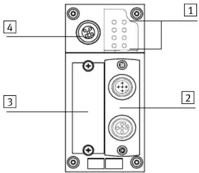
2Connectinganddisplayelements
1 Busstatusspecific andCPX-specific LEDs
2 Exchangeablefield busconnection (heremicrostyle)
3 CoveroftheDIL switches
4 Serviceinterfacefor handheld,etc.
| BusstatusLEDsCPX-specificLEDs | |||
| MS | Module status (red/green) | PS | Power system (green) |
| NS | Network status (red/green) | PL | Power load (green) |
| I/O | I/O status (red/green) | SF | System failure (red) |
| MModify(yellow) 1) | |||
| 1) ParametrizingmodifiedorForceactive | |||
InnormaloperatingstatusthefollowingLEDslightup green:PS,PL,MS,NS.
TheI/OLEDlightsupgreenonlywheninputs/outputsare controlledviaDeviceNet.TheMLEDlightsuponlywhen "SystemstartwithsavedparametrizingandCPXextension"isset.
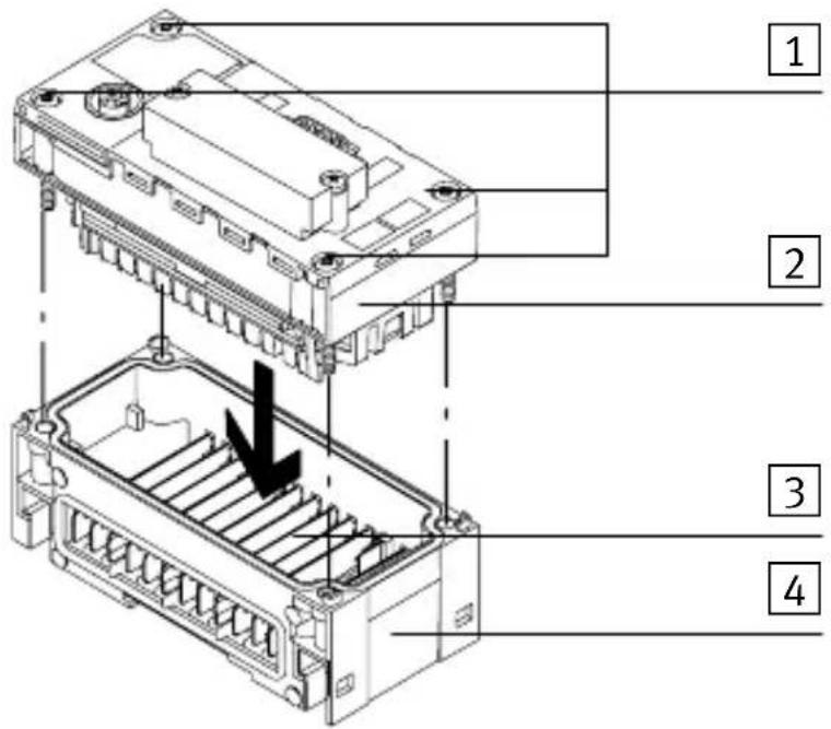
3Installationinstructions
3.1 Fitting
FieldbusnodeCPX-FB11ismountedinamanifoldbaseof theCPXterminal.
1 Screws,
tighteningtorque
0.9...1.1Nm
2 Fieldbusnode CPX-FB11
3 Contactrails
4 Manifoldbase
Dismantling
- Removethescrewsandcarefullyliftupthefieldbus node.
Fitting
- Checkthesealandsealingsurfacesandrefitthesub-base.
- Placethescrewssothattheself-cuttingthreadsare used. Tightenthescrewsbyhandindiagonallyoppositesequence. Tighteningtorque0.9...1.1Nm.
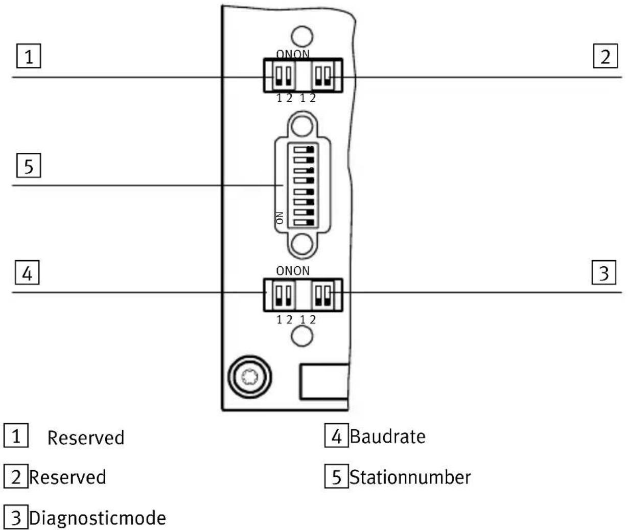
3.2DILswitchsettings
| DILswitchesDescription | ||
| 11.1 | /1.2Reserved | 1) |
| 22.1 | /2.2Reserved | 1) |
| 1) Reservedforextensions;switchelementsmustbesetto OFF | ||
| 33.1 | 3.2Diagnosis via “Polled” or “Changeofstate” connection: 3.13.2 OFFOFF: Diagnosisswitchedoff ONOFF:I/Odiagnosticinterfaceis switchedon OFFON: Statusbitsareswitchedon ONON: Reservedforextensions | |
| 44.1 | 4.2 | 4.14.2 OFFOFF: 125kBaud ONOFF: 250kBaud OFFON: 500kBaud ONON: Auto 1) |
| 55.1 | 5.2 5.3 5.4 5.5 5.6 | Fieldbusstationnumberbinarycoded (0forOFF,1forON) 5.6to 5.1 0 0 0 0 0 1 = 1 0 0 0 0 1 0 = 2 0 0 0 0 1 1 = 3 0 0 0 1 0 0 = 4 0 0 0 1 0 1 = 5 etc.; permittedvaluerange:0...63 |
| 1) Automaticbaudraterecognitionintheswitch-onphaseof theCPXterminalwhenconnectedtoabussystemwhichis running(exchangeofdatabasebetweenascannerandatleast oneslave).125KBdissetifnobaudrateisrecognized. | ||
3.3Fieldbusinterface
| Connectionaccessories | Typedesignation |
| Microstyleconnection(2xM125-pol)FBA-2-M12-5pol | |
| Openstyleconnection(5-pinterminal)FBA-1-SL-5pol | |
| Sub-Dconnection(9-pin)(isintegrated) | |
| OpenstyleterminalstripforFBA-1-SL-5polFBSD-KL-2x5pol | |
| Sub-DsocketFBS-SUB-9-BU-2x4pol |
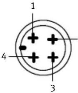
| Signal-related core colour *) | Designation | Microstyle connection 1)(optional) | Openstyle connection (optional) | Sub-D plug (integrated) |
| Red White Blank | 24VDCbus CAN_H Screening/shield | Pin2 Pin4 Pin1 | Pin5 Pin4 Pin3 | Pin9 Pin7 Pin5 |
| Blue Black | CAN_L O V b u s | Pin5 Pin3 | Pin2 Pin1 | Pin2 Pin3 |
| *) Typicalfor DeviceNet cables | Busconnec-tionvariants: | 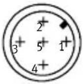 | 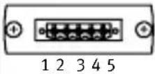 | 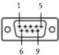 |
| 1) M12plugforBusinandM12socketforBusout | ||||
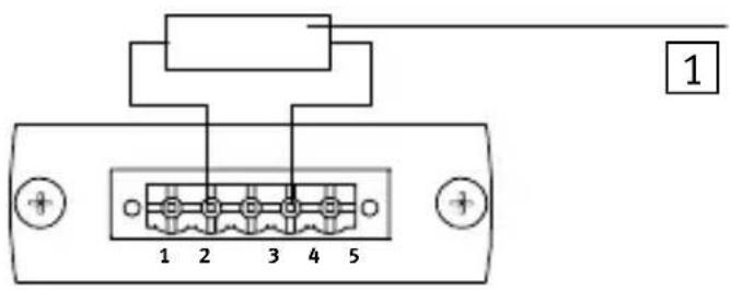
3.4 Busconnection with terminating resistors
If the CPX terminalisattheendofthefieldbussystem, a basterminationwillberequired.
1 Resistanceforbus termination betweenCAN_L andCAN_H (121Ω±1%, 0.25W)
3.5 PowersupplyfortheCPXterminal
TheoperatingandloadvoltagesuppliesfortheCPXterminalareprovidedviamanifoldbases.Thesetransmitthe operatingandloadvoltagestotheneighbouringmodules.
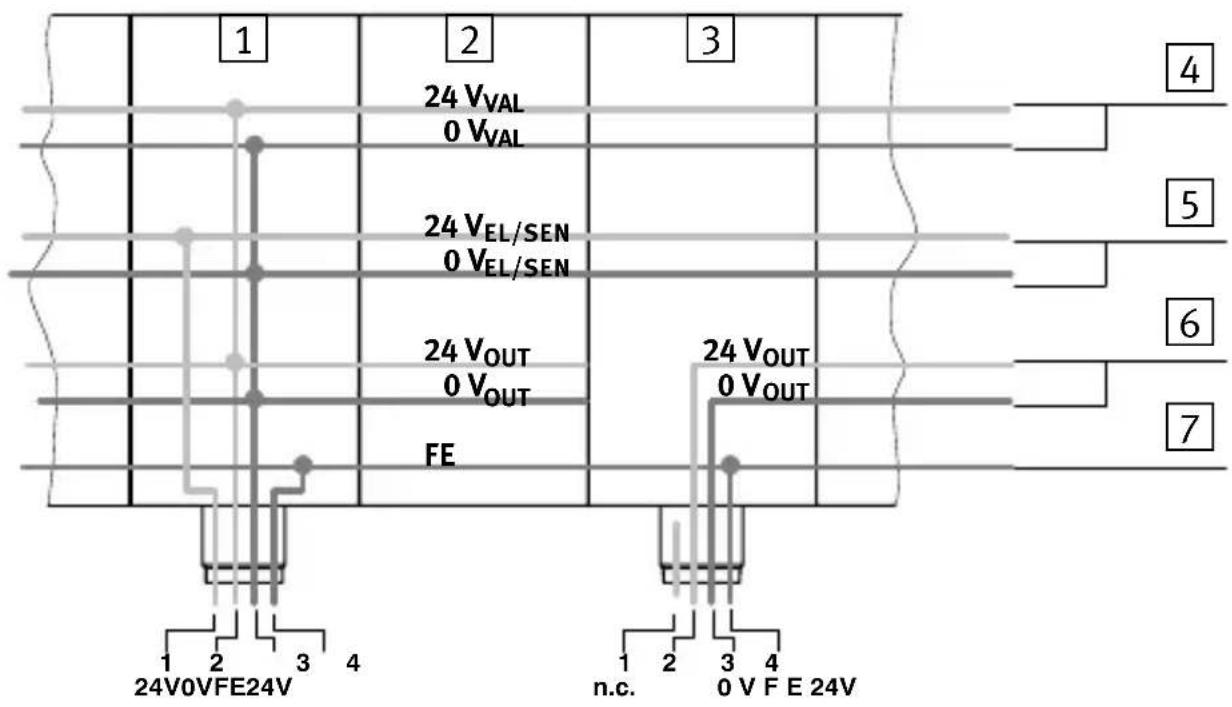
1 Manifoldbasewithsystem supplytypeCPX-GE-EV-S
2 Manifoldbasewithoutsupply typeCPX-GE-EV
3 Manifoldbasewithadditional supplytypeCPX-GE-EV-Z (pin1notassigned)
4 Loadvoltageforvalves
5 Operating voltage for the electronics and sensors
6 Loadvoltagefordigital outputs
7 Functionalearth(FE)
| Systemsupply and additional supply | Pinassignment | |
| Type CPX-GE-EV-S | Type CPX-GE-EV-... | |
 2 2 | 1.24Vsupplyfor electronicsand sensors( V_EL/SEN )2.24Vload voltagesupply forvalvesand outputs ( V_VAL/V_OUT )3.0V4.Earthing connection | 1.Notconnected2.24Vload voltage3.0V4.Earthing connection |
Connectionexample
The following diagram shows as an example the connection when as systems supply and an additional supply for electric output is used.
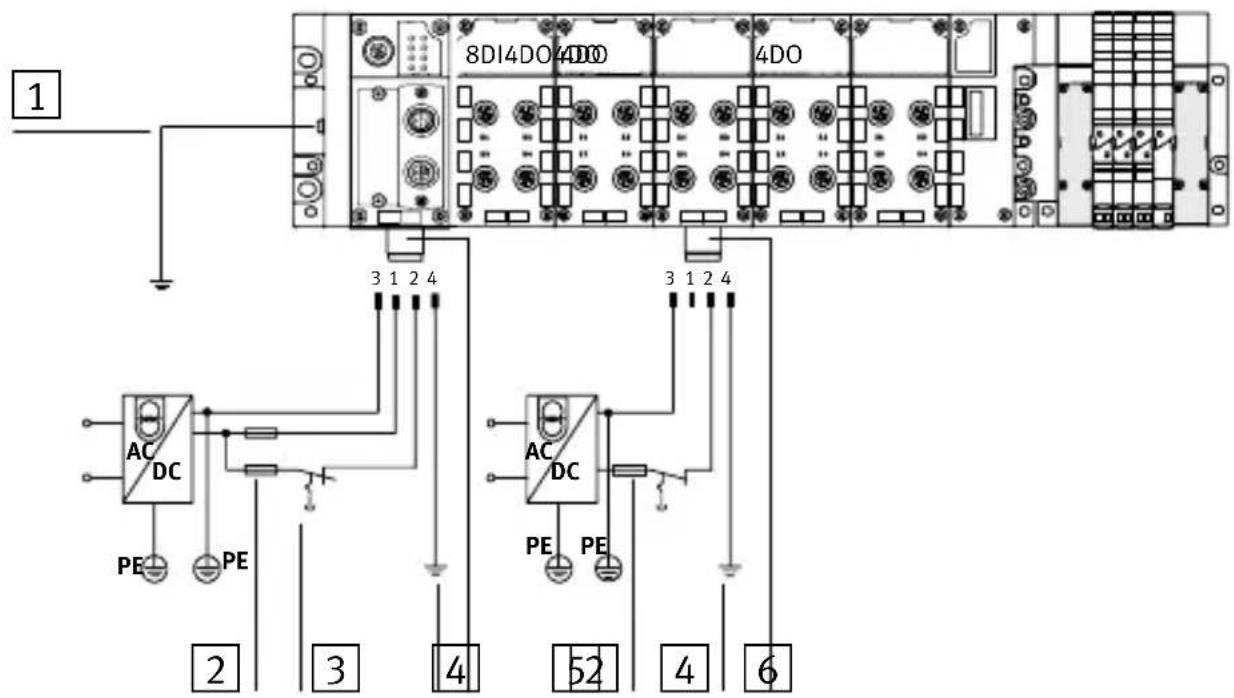
1 Potentialequalization
2 Externalfuses
3 Loadsupplyofvalves/outputs canbeswitchedoffseparately
4 Earthconnectionpin4is designedfor16A
5 Connectionfor systemsupply typeCPX-GE-EV-S
6 Connection of additional supply
forelectric outputs
typeCPX-GE-EV-Z
3.6 Start-up behaviour of the CPX terminal
If the M-LED lights uppermanently after the system start, the parameter "System start with saved parametrizing and saved CPX equipment status" is set.

Caution
In the case of CPX terminal on which the M-LED lights uppermanently, parametrizing will not be carried out automatically by the higher-order system if the CPX terminal has been replaced afterservicing. In these cases check before replacing to see which settings are required and carry out these settings.

Detailed instructions can be found in the manual for the field bus node P. BE-CPX-FB11-... or in them anual for your handheld.
4Technicalspecifications
| TypeCPX-FB11 | |
| GeneraltechnicalspecificationsSeeCPXsystemmanualP.BE-CPX-SYS-... | |
| ProtectionclassasperEN60529IP65(fittedcompletely) | |
| Protectionagainstelectricshock(protectionagainstdirectandindirectcontactasperEN60204-1/IEC204) | BymeansofPELVpowerunits(ProtectedExtra-LowVoltage) |
| Internalcurrentconsumptionat24V-Fromoperatingvoltagesupplyforelectronics/sensors( V_EL/SEN ) | Typ.65mA(internalelectronics) |
| Electricalisolation-Incominginterface-Continuinginterface | ElectricallyisolatedNon-floating |
| Modulecode(CPX-specific)204 | |
| Fieldbus- Protocol-Baudrate-Cablelength(dependingonbaudrateandcabletype) | DeviceNetasperODVA specificationV2.0125kBaud,250kBaud,and500kBaudMax.500m |
Desmontaje
Démontage:
1 Blocdedistributionavec alimentationsystèmetype CPX-GE-EV-S
2 Blocdedistributionsans alimentationsystèmetype CPX-GE-EV
3 Blocdedistributionavec alimentationauxiliairetype CPX-GE-EV-Z(broche1non occupée)
Smontaggio:
- ToglierelevitiesollevaredelicatamenteinodiFieldbus.
Montaggio:
1 Piastradiinterconnessionecon modulodialimentazionedel sistematipoCPX-GE-EV-S
2 Piastradiinterconnessionesenza modulodialimentazionetipo CPX-GE-EV
3 Piastradiinterconnessionecon modulodialimentazionesupplementaretipoCPX-GE-EV-Z (pin1nonoccupato)
4 Tensionedicaricoper valvole
5 Tensionediesercizioper lepartielettronicheedi sensori
6 Tensionedicaricoper uscitedigitali
7 Messa a terra (FE)
Demontering:
1 Kopplingsblockmed systemmatningCPX-GE-EV-S
2 Kopplingsblockutan systemmatningCPX-GE-EV
3 Kopplingsblockmedextra spänningsmatningCPX-GE-EV-Z (stift1ejbelagt)
Brand : Festo
Model : CPX-FB11
Category : Industrial controller