
RHA6 - Audio Amplifier MARANTZ - Free user manual and instructions
Find the device manual for free RHA6 MARANTZ in PDF.

| Product type | Headphone audio amplifier |
| Brand | Marantz Professional |
| Model | RHA6 |
| Number of channels | 6 independent channels |
| Number of headphone outputs | 18 (3 per channel: 1 front + 2 rear) |
| Input connectors | Balanced XLR and 6.35 mm TRS (main input); stereo auxiliary input per channel; front direct input |
| Output connectors | 6.35 mm TRS for headphones; XLR/TRS main outputs for daisy chaining |
| Power supply | Mains via supplied power cable; calibrated fuse |
| Recommended headphone impedance | 100 ohms minimum for 1 headphone, 200 ohms for 2, 300 ohms for 3 per channel |
| Format | 19-inch rack 1U (rack unit) |
| Main functions | Input gain, output gain, balance (main/aux mix), L/R mute, mono/stereo selector, LED VU meters |
| Construction | QS9000 quality certification, high-quality components, gold-plated connectors |
| Maintenance and cleaning | Disconnect before cleaning; use a dry cloth; do not use abrasive products |
| Safety | Respect power on/off sequence; do not expose to excessive sound levels; replace fuse with identical type |
| Spare parts and repairability | Standard fuse; for other repairs, contact Marantz Professional after-sales service |
| General information | Use in studio, rehearsal, stage; provides six independent mixes |
Frequently Asked Questions - RHA6 MARANTZ
User questions about RHA6 MARANTZ
0 question about this device. Answer the ones you know or ask your own.
Ask a new question about this device
Download the instructions for your Audio Amplifier in PDF format for free! Find your manual RHA6 - MARANTZ and take your electronic device back in hand. On this page are published all the documents necessary for the use of your device. RHA6 by MARANTZ.
USER MANUAL RHA6 MARANTZ
User Guide (English)
Introduction
Thanks for purchasing the Marantz Professional RHA6! RHA6 is a universal, multi-purpose mixer and headphone amplifier for rehearsal, studio, or stage. Perfect for headphones, in-ear monitors, or personal monitor mixing, RHA6 features six independent high-power stereo amplifiers in one compact rack unit that delivers maximum audio quality, even at very high or very low volume levels; RHA6 has a minimized circuitry path which means there's less "stuff" for your signal to pass through, keeping your sound clear and crisp.
• Manufactured under QS9000 certified quality system
- Six independent high-powered headphone amplifiers in a compact, 1RU size
• Supplies six fully independent mixes for up to 18 pairs of headphones
- Stereo Aux Input on each channel with level adjustments
• Additional Direct Input on front panel to mix in additional sources
• Four-segment LED on each channel for easy visual monitoring
• Mono and Left/Right Mutes per channel for two mono mixes per channel
• High-quality components and exceptionally rugged construction
- Servo-balanced, gold-plated XLR and 1/4" TRS connectors
Box Contents
RHA6
Power Cable
User Guide
Safety & Warranty Manual
Support
For the latest information about this product (system requirements, compatibility information, etc.) and product registration, visit marantzpro.com.
Sound Level
Permanent hearing loss may be caused by exposure to extremely high noise levels. The U.S. Occupational Safety and Health Administration (OSHA) has specified permissible exposures to certain noise levels. According to OSHA, exposure to high sound pressure (SPL) in excess of these limits may result in hearing loss. When using equipment capable of generating high SPL, use hearing protection while such equipment is under operation.
| Hours per day | SPL (dB) | Example | |
| 8 | 90 | Small | gig |
| 6 | 92 | Train | |
| 4 | 95 | Subway | train |
| levels | 97 | High-level | desl |
| 2 100 Classical music concert | |||
| 1.5 | 102 | Riveting | machine fact |
| 1 | 105 | Machine | |
| 0.5 | 110 | Airport | |
| 0.25 or less 115 Rock concert | |||
Features
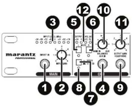
Front Panel
- Direct Input: Feeds an external audio source directly into the main signal path.
- Input Gain Control: Controls the signal level going to the Main Inputs.
- Input Level Meter: Displays the signal level coming from Main Inputs. For the best quality of input signal, the LED should range from 0 to +6 dBu. If the Clip LED (in the Output Level Meter) is always on, reduce the input level using the Input Gain Control.
-
Aux Input: Provides a separate stereo input signal which can be mixed with the Main Input signal.
-
L Mute Switch: Mutes the left input signal.
-
R Mute Switch: Mutes the right input signal.
-
Mode Switch: Switches the operational mode between mono and stereo.
-
Mono LED: This LED lights up when the unit is in mono mode. When the LED is off, the unit is in stereo mode.
-
Headphone Output: 1/4" TRS phone jack used to output the signal of the individual channel. There are also 12 additional headphone outputs (two for each channel) on the rear panel.
-
Balance Control: Sets the amount of the signal coming from the Aux Input and Main Input. When a signal is fed into the Aux Input, the balance control will regulate the ratio of the Main Input and the Aux Input signals.
-
Output Gain Control: Adjusts the output level of the individual channel.
-
Output Level Meter: Displays the output signal level. If the Clip LED lights up, turn down the input gain control and/or the individual output gain control to avoid distortion.
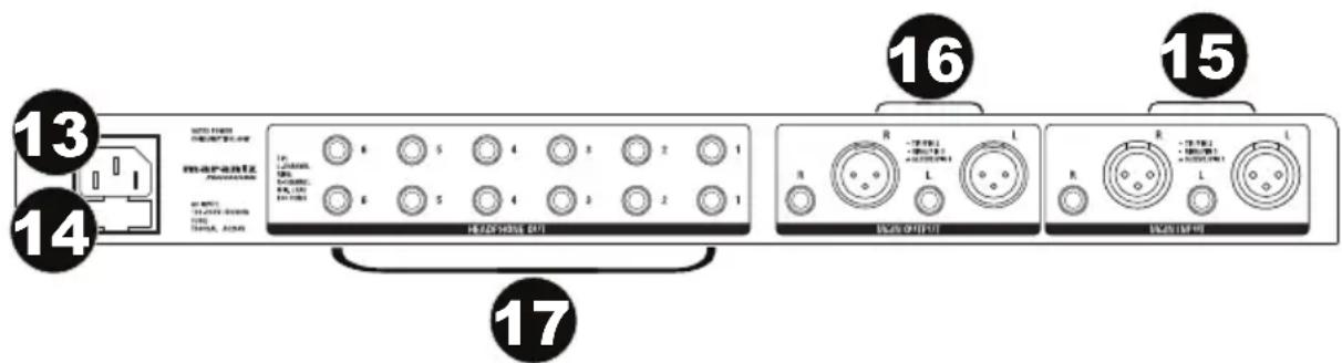
Rear Panel
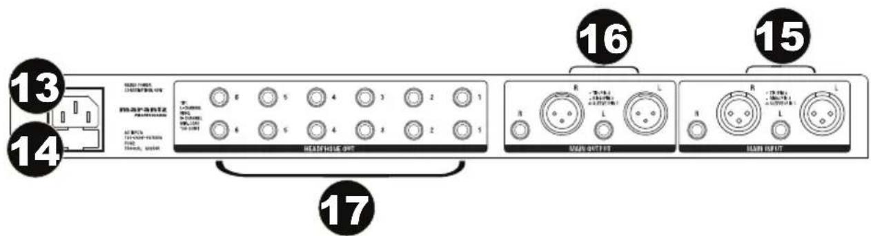
- Power Connector: Use the included power cable to connect this connector to a power source. Please check the voltage accepted by the unit and the voltage available from your power source before connecting it.
- Fuse Holder: If the fuse blows, replace it with a fuse of the same type.
- Main Input Connectors: Balanced 1/4" TRS and XLR connectors used to input the stereo signal.
- Main Output Connectors: Balanced 1/4" TRS and XLR connectors used to output the main signal. Use these connectors to link several headphone amplifiers together.
- Headphone Out (1-12): These are 12 additional headphone outputs (two for every channel) wired in parallel with the output available on the front panel.
Setup
- Switch everything on in the following order:
• audio input sources (i.e. instruments, CD/MP3 players)
• RHA6
- speakers/amps
-
When turning off, always reverse this operation:
-
speakers/amps
• RHA6 - last, any input sources
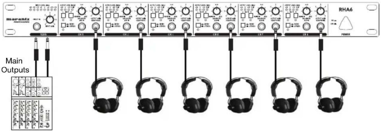
Using the Main Input Connectors
- Connect your source to the rear panel main input connectors on RHA6.
- Set the input gain (Main section) and the balance control (Channel section) on center position. Set the output gain of each channel all the way down.
- Check the input level meter for optimal signal.
- Connect headphones to RHA6 and start to raise the output gain of each channel to the desired listening volume.
Using the Aux Inputs
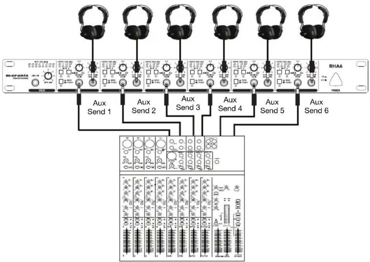
You can also play back a signal to feed in a vocal microphone and then connect a mixer's Aux send to RHA6's Aux input. Use the balance control to give the vocalist the desired mix between the voice and the playback signal. Then, adjust the output gain control to regulate the overall desired volume.
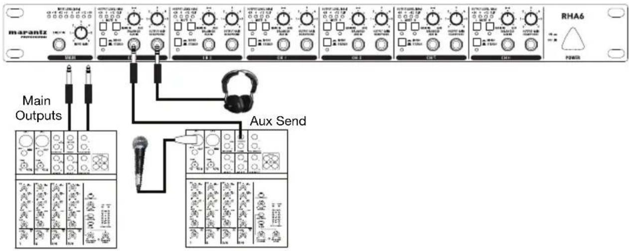
Through the Aux inputs, you can use the six channels of RHA6 independently to give individual mixes to six different musicians. Connect the Aux Sends or Subgroup outputs directly to the Aux input of RHA6. Then rotate the balance control on your RHA6 fully to the left. This will route only the Aux In signal to the headphones.
flowchart
graph TD
    A["Input: mapez RF/DC"] --> B["Aux Send 1"]
    A --> C["Aux Send 2"]
    A --> D["Aux Send 3"]
    A --> E["Aux Send 4"]
    A --> F["Aux Send 5"]
    A --> G["Aux Send 6"]
    B --> H["Output: 10x10-100 microcontroller with multiple input channels and output ports"]
    C --> H
    D --> H
    E --> H
    F --> H
    G --> H
Using Multiple Headphones on the Same Channel
Each channel provides three headphone outputs. These jacks are all connected in parallel. For best results, please note the impedance information:
- When connecting one headphone to each channel, the minimum impedance of the headphone should be 100 ohms.
- When connecting two headphones to each channel, the minimum impedance of each headphone should be 200 ohms.
- When connecting three headphones to each channel, the minimum impedance of each headphone should be 300 ohms.
Installation and Connection
Read the following section carefully. Not paying attention to the input signal level, to the routing of the signal and to the assignment of the signal will result in unwanted distortion, a corrupted signal or no sound at all.
Power Connection
Use the same fuse as marked on the fuse holder near the power connector. Connect RHA6 to a standard power outlet using the enclosed power cable.
Audio Connection
The RHA6 uses balanced XLR and 1/4" (6.35 mm) TRS phones jack. It can be connected to other units in a variety of ways to support a vast range of applications without experiencing a signal loss.
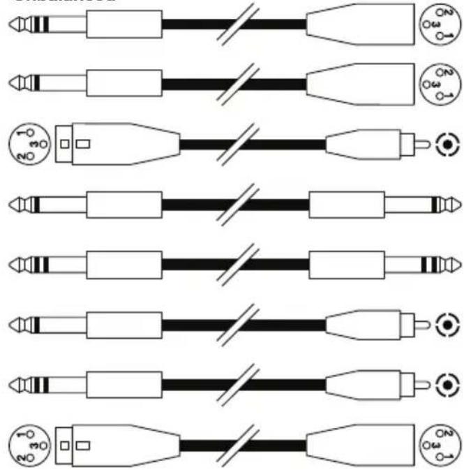
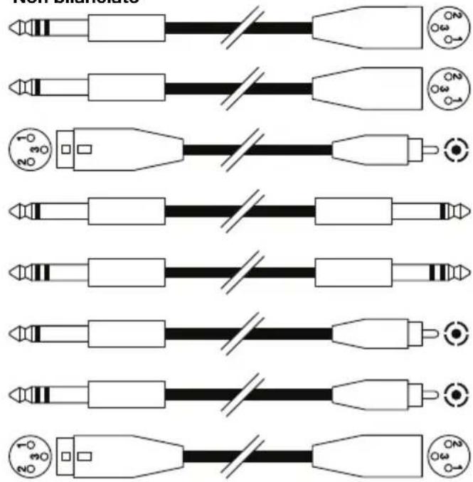
Wiring Configuration
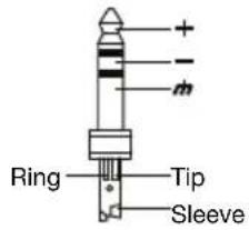
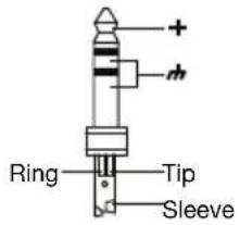
You can wire your XLR or 1/4" (6.35 mm) TRS cables as balanced or unbalanced. Here are some examples:
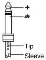
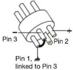
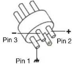
Determine the wiring configuration you need for your application and audio connections:
Balanced
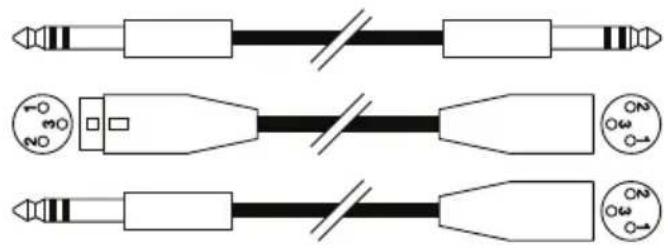
natural_image
Pure electrical connector diagram showing three types of connectors (no text or symbols)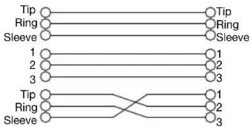
flowchart
graph TD
    A["Tip"] --> B["Tip"]
    C["Ring"] --> D["Ring"]
    E["Sleeve"] --> F["Sleeve"]
    G["1"] --> H["1"]
    I["2"] --> J["2"]
    K["3"] --> L["3"]
    M["Tip"] --> N["Tip"]
    O["Ring"] --> P["Ring"]
    Q["Sleeve"] --> R["3"]
Unbalanced
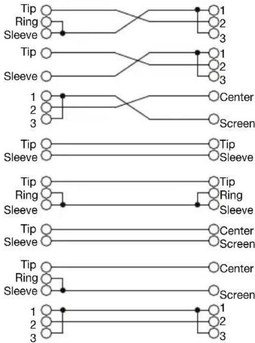
flowchart
graph TD
    A["Tip"] --> B["Ring"]
    B --> C["Sleeve"]
    C --> D["1"]
    D --> E["Center"]
    D --> F["Screen"]
    G["Tip"] --> H["Sleeve"]
    H --> I["1"]
    I --> J["Center"]
    I --> K["Screen"]
    L["Tip"] --> M["Sleeve"]
    M --> N["2"]
    N --> O["Center"]
    N --> P["Screen"]
    Q["Tip"] --> R["Sleeve"]
    R --> S["3"]
    S --> T["2"]
    T --> U["Screen"]
    V["Tip"] --> W["Sleeve"]
    W --> X["4"]
    X --> Y["3"]
    Z["Tip"] --> AA["Sleeve"]
    AA --> AB["5"]
    AB --> AC["2"]
    AC --> AD["Screen"]
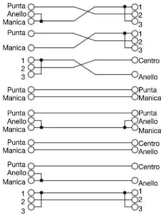
Aplicaciones
natural_image
Three schematic diagrams of electronic components connected by wires, showing pin layouts and terminal connections (no text or labels)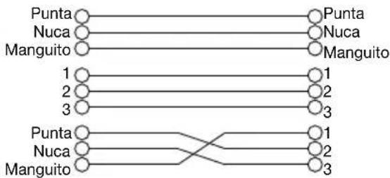
flowchart
graph TD
    A["Punta"] --> B["Punta"]
    C["Nuca"] --> D["Nuca"]
    E["Manguito"] --> F["Manguito"]
    G["1"] --> H["1"]
    I["2"] --> J["2"]
    K["3"] --> L["3"]
    M["Punta"] --> N["1"]
    O["Nuca"] --> P["2"]
    Q["Manguito"] --> R["3"]
No balanceado

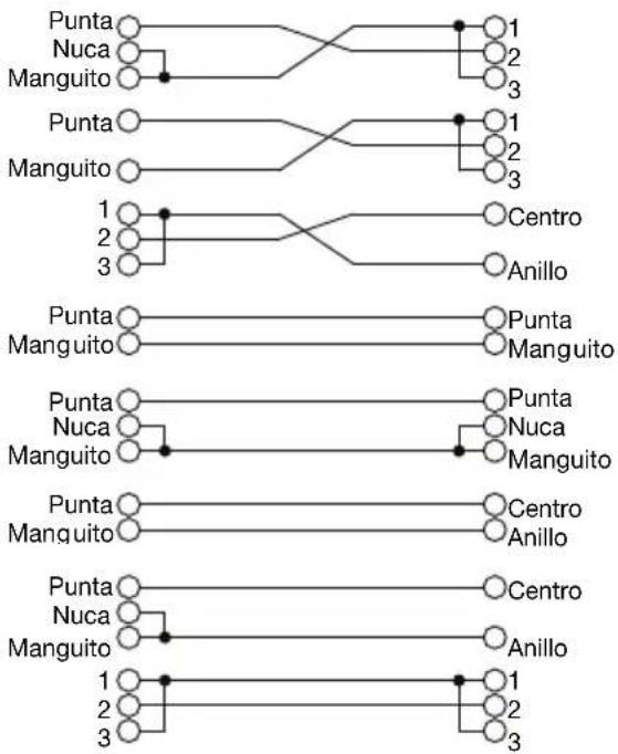
flowchart
graph TD
    A["Punta"] --> B["1"]
    C["Nuca"] --> D["2"]
    E["Manguito"] --> F["3"]
    G["Punta"] --> H["1"]
    I["Manguito"] --> J["2"]
    K["1"] --> L["Centro"]
    M["2"] --> N["Anillo"]
    O["3"] --> P["Punta"]
    Q["Punta"] --> R["Manguito"]
    S["Punta"] --> T["Punta"]
    U["Nuca"] --> V["Nuca"]
    W["Manguito"] --> X["Manguito"]
    Y["Punta"] --> Z["Centro"]
    AA["Manguito"] --> AB["Anillo"]
    AC["Punta"] --> AD["Centro"]
    AE["Nuca"] --> AF["Anillo"]
    AG["Manguito"] --> AH["1"]
    AI["1"] --> AJ["Centro"]
    AK["2"] --> AL["Anillo"]
    AM["3"] --> AN["Centro"]
Installation et raccordement
natural_image
Pure electrical connector diagram showing three types of connectors (no text or symbols)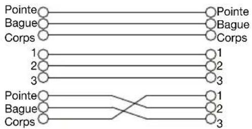
flowchart
graph TD
    A["Pointe"] --> B["Pointe"]
    C["Bague"] --> D["Bague"]
    E["Corps"] --> F["Corps"]
    G["1"] --> H["1"]
    I["2"] --> J["2"]
    K["3"] --> L["3"]
    M["Pointe"] --> N["Pointe"]
    O["Bague"] --> P["Bague"]
    Q["Corps"] --> R["Corps"]
    S["1"] --> T["1"]
    U["2"] --> V["2"]
    W["3"] --> X["3"]
Asymétrique
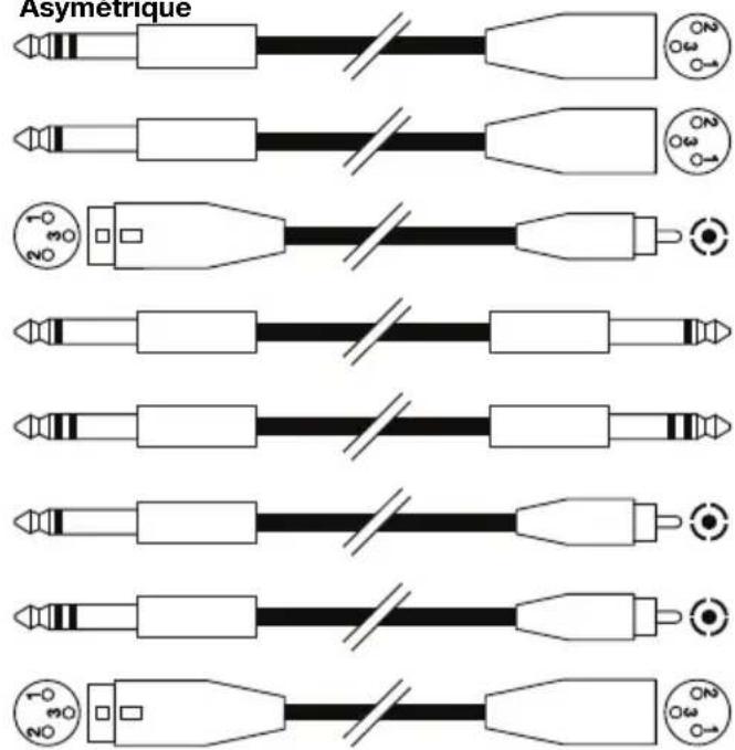
flowchart
graph TD
    A["Pointe"] --> B["1"]
    A --> C["2"]
    A --> D["3"]
    E["Bague"] --> F["2"]
    E --> G["3"]
    H["Corps"] --> I["3"]
    J["Pointe"] --> K["1"]
    J --> L["2"]
    J --> M["3"]
    N["Corps"] --> O["3"]
    P["1"] --> Q["Centre"]
    R["2"] --> S["Anneau"]
    T["3"] --> U["Centre"]
    V["Pointe"] --> W["Pointe Corps"]
    X["Corps"] --> Y["Corps"]
    Z["Pointe"] --> AA["Pointe Bague Corps"]
    AB["Corps"] --> AC["Corps"]
    AD["Pointe"] --> AE["Centre Anneau"]
    AF["Corps"] --> AG["Centre Anneau"]
    AH["Pointe"] --> AI["Centre Anneau"]
    AJ["Corps"] --> AK["Centre Anneau"]
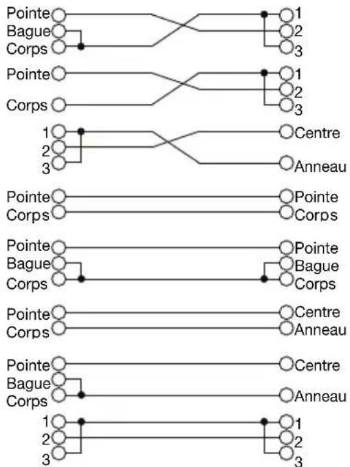
natural_image
Three schematic diagrams of electrical connectors with no text or symbols
flowchart
graph TD
    A["Punta"] --> B["Anello"]
    A --> C["Manica"]
    D["Punta"] --> E["Anello"]
    D --> F["Manica"]
    G["1"] --> H["2"]
    G --> I["3"]
    J["1"] --> K["2"]
    J --> L["3"]
    M["Punta"] --> N["Anello"]
    M --> O["Manica"]
    P["1"] --> Q["2"]
    P --> R["3"]
Non bilanciato
flowchart
graph TD
    A1["Punta"] --> B1["1"]
    A2["Anello"] --> B2["2"]
    A3["Manica"] --> B3["3"]
    B1 --> C1["Punta"]
    B2 --> C2["Anello"]
    B3 --> C3["Manica"]
    C1 --> D1["1"]
    C2 --> D2["2"]
    C3 --> D3["3"]
    D1 --> E1["Centro"]
    D2 --> E2["Anello"]
    D3 --> E3["Anello"]
    E1 --> F1["Punta"]
    E2 --> F2["Manica"]
    E3 --> F3["Punta"]
    E1 --> G1["Punta"]
    E2 --> G2["Anello"]
    E3 --> G3["Manica"]
    G1 --> H1["Punta"]
    G2 --> H2["Anello"]
    G3 --> H3["Centro"]
    G1 --> I1["Centro"]
    G2 --> I2["Anello"]
    G3 --> I3["Anello"]
    I1 --> J1["1"]
    I2 --> J2["2"]
    I3 --> J3["3"]
Technical Specifications
| Inputs | |
| Connectors | XLR and 1/4" (6.35 mm) |
| Type | Electronically servo-balanced, RF-filtered |
| Impedance | Balanced: >50 KΩUnbalanced: >25 KΩ |
| Maximum Input Level | +21 dBU typical, balanced or unbalanced |
| Aux In and Direct In | |
| Connectors | 1/4" (6.35 mm) TRS (tip = left; ring = right; sleeve = ground) |
| Impedance | Unbalanced: >25 KΩ |
| Maximum Input Level | +21 dBU, balanced or unbalanced |
| Output | |
| Connectors | XLR and 1/4" (6.35 mm) |
| Type | Balanced/Unbalanced |
| Maximum Output Level | +21 dBu, balanced and unbalanced |
| Power Amplifier | |
| Maximum Output Power | +21 dBmW |
| Min. Output Impedance | 100 Ω |
| Maximum Gain | +20 dB |
| Performance | |
| Frequency Response | 10 Hz - 50 kHz, +0/-3 dB |
| Signal-to-Noise Ratio | >90 dB, unweightedReference: +4 dBu, 22 Hz - 22 kHz |
| THD | 0.005%Reference: +4 dBu |
| Power | Power Consumption: 14 wattsInput Voltage: 120 V AC, 60 Hz; 230-240 V AC, 50 Hz |
| Dimensions(width x depth x height) | 19.0" x 8.54" x 1.7"483 mm x 217 mm x 44 cm |
| Weight | 6.4 lbs.2.9 kg |
Specifications are subject to change without notice.
Trademarks & Licenses
Marantz is a trademark of D&M Holdings Inc., registered in the U.S. and other countries.
All other product or company names are trademarks or registered trademarks of their respective owners.
marantzpro.com

- User Guide (English)
- Introduction
- Box Contents
- Support
- Sound Level
- Features
- Front Panel
- Rear Panel
- Setup
- Using the Main Input Connectors
- Using the Aux Inputs
- Using Multiple Headphones on the Same Channel
- Installation and Connection
- Power Connection
- Audio Connection
- Wiring Configuration
- Aplicaciones
- Installation et raccordement
- Trademarks & Licenses
- marantzpro.com
Brand : MARANTZ
Model : RHA6
Category : Audio Amplifier