
EKOMBG22ABV1 - Boiler DAIKIN - Free user manual and instructions
Find the device manual for free EKOMBG22ABV1 DAIKIN in PDF.

| Product Type | Wall-mounted condensing gas boiler |
| Brand | Daikin |
| Model | EKOMBG22ABV1 |
| Dimensions (H x W x D) | 590 x 450 x 240 mm |
| Weight | 30 kg |
| Power supply | 230 V ~ 50 Hz, IPX4D |
| Heating power (CH) | 6.0 to 22.6 kW |
| DHW power | Up to 25.9 kW (Hs) |
| Seasonal energy efficiency class | A |
| Max CH pressure | 3 bar |
| Max CH temperature | 90 °C |
| Adjustable DHW temperature | 40 to 65 °C |
| Compatible gas types | G20 (20 mbar), G25 (25 mbar), G31 (37 mbar) |
| Flue pipe | Concentric 60/100 or 80/125, parallel 80 mm |
| Main functions | Modulation, tap comfort (eco/on/off), frost protection, self-test, PC interface |
| Recommended maintenance | Annual cleaning of the heat exchanger and siphon by an approved installer |
| Safety protection | Flame detection, pressure safety, temperature safety, automatic shutdown |
| Spare parts and accessories | Pack B, valve kit, outdoor sensor, propane kit, flue adapters |
| Warranty | Subject to conditions, requires annual maintenance by approved installer |
Frequently Asked Questions - EKOMBG22ABV1 DAIKIN
User questions about EKOMBG22ABV1 DAIKIN
0 question about this device. Answer the ones you know or ask your own.
Ask a new question about this device
Download the instructions for your Boiler in PDF format for free! Find your manual EKOMBG22ABV1 - DAIKIN and take your electronic device back in hand. On this page are published all the documents necessary for the use of your device. EKOMBG22ABV1 by DAIKIN.
USER MANUAL EKOMBG22ABV1 DAIKIN
natural_image
White industrial water heater device with a cylindrical top and control panel (no visible text or symbols)EKOMBG22ABV1
EKOMBG28ABV1
EKOMBG33ABV1
Installation instructions
1 Safety instructions 5
2 Unit description 5
2.1 General 5
2.2 Functioning....5
2.3 Operating modes 5
2.4 PC Interface 7
2.5 Test programs 7
3 Main components 9
3.1 Accessories 10
4 Installation 11
4.1 Installation measurements 11
4.2 Installation space....13
4.3 Assembly....14
5 Connecting 16
5.1 Connecting CH installation....16
5.2 Connecting DHW installation....18
5.3 Connecting electronically....19
5.4 Connect room thermostat....20
5.5 Connecting gas 21
5.6 Flue and air supply duct 22
5.7 Outlet systems....23
5.8 Flue material....24
5.9 Connection to a flue system without air inlet (B23, B33)....26
5.10 Connection to a sealed flue system....27
6 Commissioning the unit and the Installation 35
6.1 Filling and air purge of unit and installation 35
6.2 Commissioning the unit 36
6.3 Switching off the unit 37
7 Setting and adjustment 38
7.1 Direct via operating panel....38
7.2 Parameter settings via the service code 39
7.3 Setting maximum CH power....41
7.4 Set pump capacity 41
7.5 Weather dependent regulation 41
7.6 Conversion to different type of gas....42
7.7 Gas/air regulation 42
7.8 Setting gas/air regulation....43
8 Malfunctions
8.1 Show last malfunction 45
8.2 Malfunction codes 45
8.3 Other faults 46
9 Maintenance
9 Technical specifications
9.1 Technical Product Fiche in accordance to CELEX-32013R0811....52
9.2 Electrical diagram....53
9.3 NTC resistances....54
10
Warranty conditions 55
© 2022 Daikin Europe NV
All rights reserved.
The information provided applies to the product in its standard version. Daikin Europe NV can therefore not be held liable for any damages arising from any specifications of the product which deviate from the standard version. The available information has been compiled with the greatest possible care, but Daikin Europe NV can not be held liable for any mistakes in the information, or for any consequences thereof. Daikin Europe NV cannot be held liable for any damage arising from work carried out by third parties.
Subject to change.
These installation instructions
With these installation instructions, you can safely assemble, install and maintain the unit. Carefully follow the instructions.
In case of any doubt, please contact the manufacturer.
Keep the installation instructions near the unit.
Abbreviations and terms used
| Description | To be referred to as |
| Daikin EKOMBG22ABV1, EKOMBG28ABV1 and EKOMBG33ABV1 wall-mounted gas boiler. | Unit |
| Unit with piping for central heating | CH installation |
| System with pipes for domestic hot water | DHW installation |
Symbols
The following symbols are used in this manual:

CAUTION
Procedures which - if they are not carried out with the necessary care - may cause damage to the product, the surroundings, the environment or injury.

IMPORTANT
Procedures and/or instructions which, if they are not followed, will have a negative effect on the functioning of the unit.
Service and technical support for the installer
For information about specific settings, installation, maintenance and repair work, as an installer, please contact your local Daikin dealer.
Identification of the product
You will find the unit details on the data plate on the bottom of the unit.
The data plate contains, beside the supplier information and the boiler specification (boiler type and model name) the following information:
| ******-yymm****** | Product code-Serial No.YY= year of production, mm = month of production |
| PIN | Product Identification Number |
| Data related to Domestic Hot Water | |
| Data related to Central Heating | |
| Information regarding electrical power supplyVoltage, mains frequency, elmax, IP-class) | |
| PMS | Permissible overpressure in CH circuit in bar |
| PWS | Permissible overpressure in DHW circuit in bar |
| Qn HS | Input related to gross caloric value in kilowatts |
| Qn Hi | Input related to net caloric value in kilowatts |
| Pn | Output in kilowatts |
| BE, DE, GR, IT,PT, FR, PL | Countries of Destination (EN 437) |
| I2E(s), I2H,I1ELL3P, II2H3P,II2Esi3P | Approved unit categories (EN 437) |
| G20-20 mbarG25-25 mbar | Gas group and gas connection pressure as set at thefactory (EN 437) |
| B23, .... C93(x) | Approved flue gas category (EN 15502) |
| Tmax | Max. flow temperature in °C |
| IPX4D | Electrical protection class |
1 SAFETY INSTRUCTIONS
The manufacturer Daikin accepts no liability for damage or injury caused by the failure to (strictly) observe the safety instructions, or negligence during the installation of the Daikin EKOMBG*ABV1 wall-mounted gas boiler and any associated accessories.
Depending on the year of construction, an Daikin EKOMBG*ABV1 may contain a part which contains ceramic fibres. This can apply to the gasket of the inspection glass and the isolation package of the front plate. Always use the recommended personal protective equipment when working with ceramic fibres.

IMPORTANT
This product is intended for domestic use only.
This device is not intended for use by people (including children) with reduced physical, sensory or mental abilities, or lack of experience and knowledge, unless they are given supervision or instructions on the use of the device by a person who is responsible for their safety.
The instructions are stated separately for the various disciplines.
The entire installation must meet the applicable local technical and (safety) instructions, for the gas installation, the electrical installation, smoke extraction installation, drinking water installation, and central heating installation.
2 UNIT DESCRIPTION
2.1 General
The Daikin EKOMBG*ABV1 wall-mounted gas boiler is a closed unit. The unit is intended to provide heat to the water of a CH-installation and the domestic hot water installation.
The air supply and the combustion gas outlet of the EKOMBG*ABV1 can be connected to the unit by two separate pipes, or by a concentric connection. The unit was tested in combination with the combi feedthrough, but the unit may also be connected to combi feedthroughs which meet the universal test standards for combi feedthroughs.
The unit can be connected to an assembly bracket if required, a frame with top connection, and various installation sets. These are provided separately.
The Daikin EKOMBG*ABV1 wall-mounted gas boilers have the CE quality mark, electrical protection class IPX4D.
It is possible to use the unit solely for warm water, or solely for heating. The system which is not in use, does not need to be connected (see par. 7.2).
The unit is delivered for natural gas (G25) as a standard. On request, the unit can also be provided for propane (G31).
2.2 Functioning
The Daikin EKOMBG*ABV1 wall-mounted gas boiler is a modulating high-efficiency boiler. This means that the power is modulated to suit the required heat demand. In the aluminum heat exchanger two separate copper circuits are integrated.
The separate circuits for CH and warm water allow the heating and warm water supply to function independently. The hot water supply takes precedence over the heating. Both cannot work at the same time.
The unit is fitted with an electronic boiler controller machine, which operates the fan and the modulating pump at every heat requirement of the heating or the warm water supply, opens the gas valve, ignites the boiler controller, and continuously monitors and regulates the flame, depending on the requested power. The pump is only operated during a heat request from the heating, depending on the requested power.
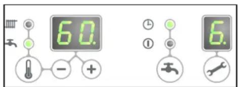
2.3 Operating modes
The operating mode of the unit is indicated by means of a code on the service display of the operating panel.

The unit is not in operation, but is connected to the electricity supply. No response is given to requests for domestic hot water or CH water. The unit frost protection is active. This means that the pump will start running and the exchanger will be heated up if the temperature of the water in the system drops too far.

natural_image
Line drawing of a rectangular electronic device with a cylindrical top and side buttons (no text or symbols)If the frost protection intervenes, the code 7 will be displayed (heating up exchanger). The pressure in the CH installation can also be read from the temperature display in this operating mode (in bar).

Standby
The LED at the key is lit and possibly one of the LEDs of the tap comfort function. The unit is ready to respond to a request for CH or tap water.

Post-running CH
After the end of the CH-operation, the pump will post-run. The post-pumping time is set to the value in par. 7.2 in its factory settings. This setting can be changed. In addition to this, the pump will run automatically 1 time per 24 hours, for 10 seconds, in order to prevent it from getting stuck. This automatic switching on of the pump takes place at the time of the last heating request. In order to change this, the room thermostat needs to be set higher for a moment, at the required time of day.

Requested temperature reached
The boiler controller may temporarily block the heat request. The boiler controller will then be stopped. The block occurs because the required temperature has been reached. When the temperature has sufficiently decreased, the block will be lifted.

Selftest
Once every 24 hours, the boiler controller tests the connected sensors. During the test, the controller will not carry out any other tasks.

Ventilating
When the unit is started, the fan is first brought up to its correct start rpm. When the start rpm is reached, the boiler controller will be ignited. Code 3 is also visible when there is post-fanning after the boiler controller is stopped.

Igniting
When the fan has reached the start rpm, the boiler controller will be ignited by means of electrical sparks. During the ignition, code 4 is displayed. If the boiler controller does not ignite, a new attempt will be made after approximately 15 seconds. If after 4 ignition attempts, the boiler controller has still not been ignited, the controller will go into downtime.

CH-operation
An on/off thermostat, an OpenTherm thermostat, an outdoor sensor or a combination thereof can be connected to the controller (see par. 9.2)
When there is a heat request from a thermostat, after the fan has started running (code 3), the ignition will take place (code 4) followed by the CH operating mode (code 5).
During CH operation, the rpm of the fan and therefore the power of the unit can be adjusted so the temperature of the CH water to the required CH supply temperature can be controlled. If an on/off thermostat has been connected, this will be the CH supply temperature set on the display. In case of an OpenTherm or wireless thermostat, the required CH supply temperature is determined by the thermostat. In case of an outdoor sensor, the required CH supply temperature is determined by the fuel line programmed in the boiler controller. For the last two situations, the temperature set on the display is the maximum.
During CH operation, the requested CH supply temperature will be displayed on the operating panel.
The CH supply temperature can be set between 30 and 90°C (see par. 7.1). Caution: for a low temperature system, a lower maximum setting may be required than the standard setting of 80°C.
You can press the service button during CH operation to read the actual CH supply temperature.
If the tap comfort function is switched on (see code 7), an OpenTherm heat request of less than 40 degrees will be generated.

Domestic hot water operation
The hot water supply takes precedence over the heating. If the flow switch senses a request for more than 2 l/min of domestic hot water, any CH requests will be interrupted. After the fan has switched on (code 3) and there has been an ignition (code 4), the controller will switch to domestic water operation (code 5). During
domestic hot water operation, the rpm of the fan, and therefore the power of the unit, is controlled by the controller on the basis of the set tap water temperature.
The control system ensures the tap water temperature is correct. The water temperature can be set between 40^ C and 65^ C (see par. 7.1).
The set tap water temperature is displayed on the operation panel. The standard setting is 60^ C. You can press the service button during tap water operation to read the actual tap water temperature.
7 Heating up unit
In order to provide a fast supply of domestic hot water, a so-called tap comfort function has been installed in the unit. This function keeps the heat exchanger at the right temperature (it can be set, see par. 7.2). The tap comfort function has the following settings:
- On: (① LED on) The tap comfort function of the unit is continuously switched on. The unit always immediately provides warm water.
- Eco: ( ⏻ LED on) The tap comfort function of the unit is self-learning. The unit will adjust to the usage pattern of the domestic hot water. This means the heat exchanger will not be kept warm during the night or during longer absences.
- Off: (Both LEDs off) The heat exchanger is not kept warm which means the supply of domestic hot water takes a bit of time. If there is no need for fast delivery of domestic hot water, the tap comfort function can be switched off.
In the settings "on" ① and "eco" ⏻, the unit meets the requirements of the Gaskeur [Gas Inspection] CW standards.
2.4 PC Interface
The boiler controller is provided with an interface for a PC. A PC can communicate with the CH boiler by means of a special dongle, and the associated software. This facility enables you to follow the behavior of the boiler controller, the unit and the heat installation over a long period.
2.5 Test programs
There is an option in the boiler controller, to bring the unit into a test status.
Activating a test program, will switch on the unit with a set fan rotations per minute, without the control functions intervening.
The safety functions do remain active.
The test program is ended by pressing and simultaneously.
Test programs
| Description of program | Button combination | Display reading |
| Burner on with minimum DHW capacity (see parameter d par. 7.2) | and | "L" |
| Burner on with set maximum CH power (see parameter 3 par. 7.2) | and (1x) | "h" |
| Burner on with maximum DHW power (see parameter 3 par. 7.2) | and (2x) | "H" |
| Switching off test program | and | Current operation situation |
During test mode the following data can be read :
- By pressing the + button continuously in the display the CH water pressure is shown.
- By pressing the - button continuously in the display the ionisation current is shown.
2.5.1 Frost protection
- The unit is fitted with frost protection in order to prevent it from freezing. If the temperature of the heat exchanger drops too low, the pump will start running until the temperature of the heat exchanger is sufficiently high. If the frost protection intervenes, coc 7 will be displayed (heating up exchanger).
- If the installation (or a part thereof) can freeze, the coldest place should be fitted with an (external) frost thermostat on the return pipe. This must be connected in accordance with the electrical diagram (see par. 9.2).
Note
When the unit is switched off (☐ on the service display), the unit frost protection will remain active, however a heat request from an (external) frost thermostat will be ignored.
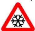
3 MAIN COMPONENTS
A. CH pump
B. Gas valve
C. Burner controller (incl. operating panel)
D. Sensor S1 (flow)
E. Sensor S2 (return)
F. Fan
G. Flow sensor
H. Pressure sensor central heating
I. Connection wire 230 V \~ with earthed plug
J. Manual air bleed
K. Sight glass
L. Air supply (only when using twin pipe flue system)
M. Flue gas/air inlet concentric adapter
N. Connection block / terminal strip X4
O. Condensate drain pan
P. Domestic hot water sensor S3
Q. Siphon
R. Heat exchanger
S. Operating panel and display
T. Ionization / ignition pen
U. Position of data plate
3.1 Accessories
| Description | Article numbers | |
| B-pack EKFJS*AA (1) | EKFJS*AA | |
| B-pack middle (1) | EKFJM*AA | |
| B-pack large (1) | EKFJL*AA | |
| Valve kit (1) | EKVK4AA | |
| Cover plate EKOMBG*ABV1 | EKCP1AA | 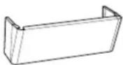 |
| Outdoor sensor | EKOSK1AA | |
| 3-way valve set | EK3WV1AA | |
| Flue gas adapter Concentric ∅80x125 | EKHY090717 |  |
| Flue gas adapter Parallel 80 mm | EKHY090707 | |
| Propane set EKOMBG22ABV1 | EKPS075877 | |
| Propane set EKOMBG28ABV1 | EKPS075867 | |
| Propane set EKOMBG33ABV1 | EKHY075787 |
(1) This set contains a gas valve that complies to EN 331 with the following specifications:
• DN15
- Pressure class (MOP)5
• High temperature class C

CAUTION
- Make sure the valve meets re requirements for the application
- Do not use the gas valve in case of visible damage
- Do not make any modifications to the valve
- Instructions included with the valve must be followed
- Local legislation must be followed
4 INSTALLATION
4.1 Installation measurements
Unit with pipes connected downwards:
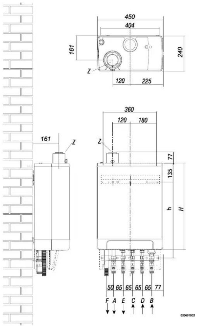
Unit + wall mounting strip
| A = | Supply CH | G 34" (ext) |
| B = | Return CH | G 34" (ext) |
| C = | Gas | G 12" (int) |
| D = | Tap water cold | R 12" |
| E = | Tap water warm | R 12" |
| F = | Condense outlet | ∅ dn25 (flexible) |
| h= | 517mm | EKOMBG22ABV1 |
| 577mm | EKOMBG28ABV1 | |
| 637mm | EKOMBG33ABV1 | |
| H= | 590mm | EKOMBG22ABV1 |
| 650mm | EKOMBG28ABV1 | |
| 710mm | EKOMBG33ABV1 | |
| Z = | Flue gas outlet/air inlet | ∅60/100 (concentric) |
Unit connected to B-pack:
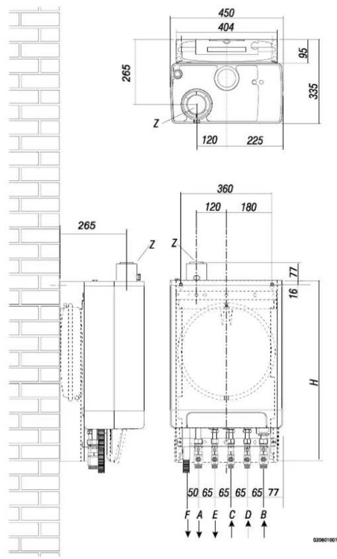
Unit + B-pack
| A = | Supply CH | G 3/4" (ext) |
| B = | Return CH | G 3/4" (ext) |
| C = | Gas | G 1/2" (int) |
| D = | Tap water cold | R 1/2" |
| E = | Tap water warm | R 1/2" |
| F = | Condense outlet | ∅ dn25 (flexible) |
| H= | 770mm | EKOMBG22ABV1 |
| 830mm | EKOMBG28ABV1 | |
| 890mm | EKOMBG33ABV1 | |
| Z = | Flue gas outlet/air inlet | ∅60/100 (concentric) |
4.2 Installation space
The unit must be installed against a wall with sufficient load bearing capacity.
In case of light wall constructions, there is a risk of resonance noises.
Within 1 meter of the unit, there must be a earthed wall plug.
In order to prevent the condense outlet from freezing, the unit must be installed in a frost-free room. Preferably ensure there is a space of at least 2 cm next to the boiler. No free space is required due to danger of singing.

IMPORTANT
The unit must not be installed in a space where work is carried out with aggressive or corrosive gases such as hairspray.
4.2.1 Installing in kitchen cabinet
The unit can be placed between two kitchen cabinets, or inside a kitchen cabinet.
Make sure there is sufficient ventilation at the bottom and the top.
If the unit is installed inside a cabinet, ventilation openings of at least 50 cm ^2 are required.
4.2.2 Removing cover plate and front panel
For various activities on the unit, the cover plate and front panel have to be removed from the unit, if they were installed. Do this as follows:
- If you are using the cover plate (A), remove it to the front.
- Unscrew both screws (1) behind the display window.
- Pull the bottom of the front panel (2) forwards.
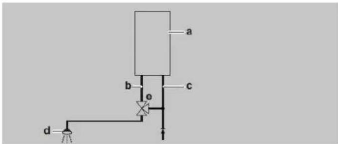
Danger: risk of burning
In case of high leaving water set ponts for space heating (eighter a high fixed set point or a high weather-dependent set point at low ambient temperatures), the heat exchanger of the boiler can be very hot, for example 70°C.
Beware that in case of a tapping demand, the water can initially have a higher water temperature than requested.
In this case, it is recommended to install a thermostatic valve to prevent scalding. This can be done according to the schematics below.
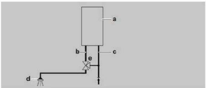
a=boiler, b=DHW from boiler, c=cold water inlet, d=shower, e=thermostatic valve (field supply)

natural_image
Technical line drawing of a mechanical assembly with labeled component A (no text or symbols beyond label)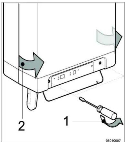
4.3 Assembly
The boiler can be hung to the wall using :
- the wall suspension strip and a the connection kit EKVK4AA
• a B-pack including an expansion vessel and a connection kit.
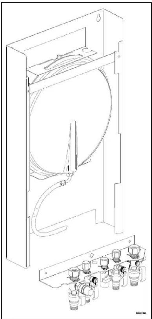
4.3.1 Assembling suspension strip and assembly bracket
• Make sure the construction of the wall is suitable for hanging the boiler.
- Drill the holes for the suspension strip and the connection kit in the wall using the template delivered with the boiler.
- Mount the suspension strip and the assembly bracket horizontally on the wall, using the associated attachment materials.
- Place the filling loop on the connections of the return and cold water nipple following the connection kit installation instruction
- The boiler can now be placed on the suspension strip simultaneously sliding the pipes of the boiler into the valves in the assembly bracket.
natural_image
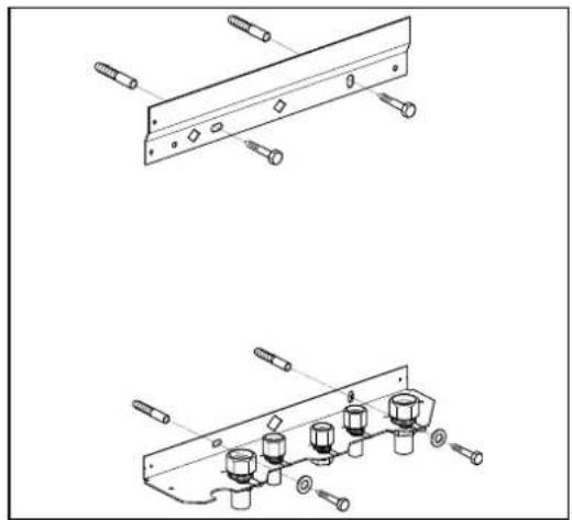
Technical line drawings of mechanical components with bolts and connectors (no text or symbols)4.3.2 Assembling bottom connection set
- Make sure the construction of the wall is suitable for hanging the boiler and B-pack.
- Drill the holes for the B-pack kit in the wall using the template delivered with the boiler.
- Mount the B-pack on the wall using the associated attachment materials.
- Place the assembly bracket in the frame as described in the manual included in the B-pack.
- Connect the flexible hose on the expansion vessel and the convection on the return valve. Make sure the seal rings are placed!
- Place the filling loop on the connections of the return and cold water nipple following the connection kit installation instruction
- The boiler can now be placed on B-pack simultaneously sliding the pipes of the boiler into the valves in the assembly bracket
natural_image
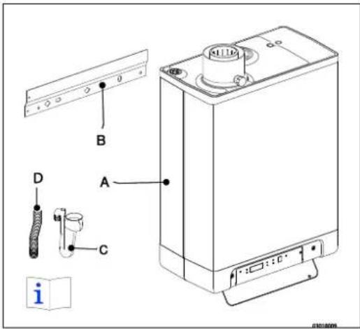
Technical line drawing of a mechanical device with internal components and housing (no text or symbols)4.3.3 Assembling the unit
-
Unpack the unit.
-
Check the content of the packaging, which consists of:
-
Unit (A)
- Suspension strip (B)
- Siphon (C)
- Flexible tube (D)
• Installation instructions - Operating instructions
-
Warranty card
-
Check the unit for any damage: immediately report damages to the supplier.
- Install the suspension strip.
- Check whether the compression rings are positioned straight in the couplings of the assembly bracket.
- Position the unit: slide it from top to bottom over the suspension strip (B). Make sure the pipes slide into the compression fittings simultaneously.
- Tighten the compression fittings onto the assembly bracket. The nipples and pipes must not rotate with it!
- Open the display valve and loosen the two screws on the left and right of the display, and remove the front panel.
- Assemble the flexible tube (D) onto the outlet of the siphon.
- Fill the siphon with water, and slide it as far as possible on top of the condense output connector (E) under the unit.
- Seal flexible tube (D) of the siphon, if possible together with the overflow pipe of the inlet combination and the overflow valve, to the sewage via open connection (F).
- Assemble the air supply and the burning gas outlet (see par. 5.6).
- Assemble the cover and tighten the two screws to the left and the right of the display, and close the display cover.

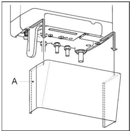
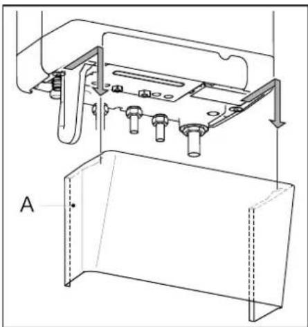
4.3.4 Apply cover plate (optional)
Suspend the converted top edge of the cover plate from the washers underneath the bottom of the unit, and slide the cover plate as far back as possible.
Danger: risk of burning
In case of high leaving water set ponts for space heating (eighter a high fixed set point or a high weather-dependent set point at low ambient temperatures), the heat exchanger of the boiler can be very hot, for example 70^ C.
Beware that in case of a tapping demand, the water can initially have a higher water temperature than requested.
In this case, it is recommended to install a thermostatic valve to prevent scalding. This can be done according to the schematics below.
a=boiler, b=DHW from boiler, c=cold water inlet, d=shower, e=thermostatic valve (field supply)

natural_image
Technical line drawing of a mechanical assembly with mounting brackets and bolts (no text or symbols)5 CONNECTING
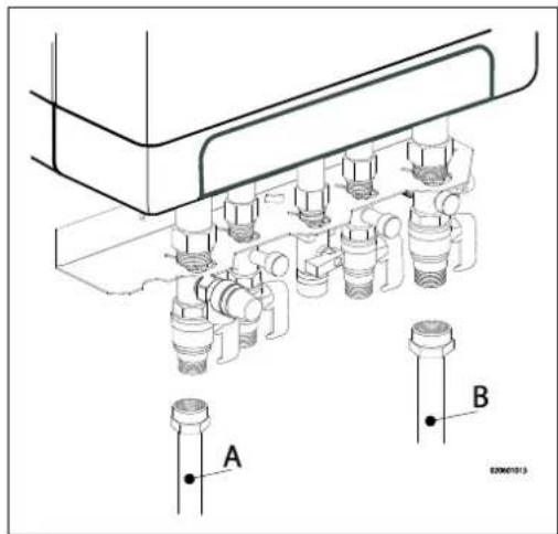
5.1 Connecting CH installation
- Rinse the CH installation carefully.
- Fit the supply pipe (A) and return pipe (B) to the connection set.
- All pipes must be assembled with no electrical current, in order to prevent shocks from the pipes.
- Existing connections may not be rotated, in order to prevent leakages.
The CH installation must be fitted with:
• A filling/draining tap (A) in the return pipe, immediately underneath the unit.
- A draining tap at the lowest point of the installation.
- An overflow valve (B) of 3 bar in the input pipe at a distance of no more than 500 mm from the unit.
Between the unit and the overflow valve there may be no valve or constriction.
• An expansion vessel in the return pipe (in the B-pack or in the installation).
- A check valve, if there are pipes running up, within close distance of the unit. This prevents a thermosiphon effect from occurring during tap water operation (a non spring-operated return valve, must be assembled vertically).
5.1.1 Thermostatic radiator taps
If all radiators are fitted with thermostatic or cable radiator taps, a minimum water circulation must be safeguarded. See par. 7.3.
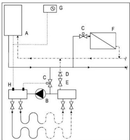
5.1.2 Underfloor heating
Underfloor heating with pump
If an underfloor heating system is not hydraulically neutral, the underfloor heating pump may generate unwanted circulation over the CH boiler. For a good functioning of the domestic hot water provision, unwanted circulation over the CH boiler must be prevented.
Connect an underfloor heating system indirectly hydraulically neutrally or provide the CH installation with a two-way valve set 230 V \~ (E). If the underfloor heating pump absorbs heat via the return of the boiler, unwanted circulation can be prevented by means of a check valve (D).
Make sure there is a minimal water circulation. See par. 7.3.
Connection diagram underfloor heating
A. CH boiler
B. CH pump
C. Thermostatic control valve
D. Spring-operated check valve
E. Electrical valve 230 V \~
F. Radiators
G. Space/clock thermostat
H. Maximum thermostat
flowchart
graph TD
    A["Component A"] -->|Flow| B["Component B"]
    B -->|Control| C["Component C"]
    C -->|Flow| D["Component D"]
    D -->|Control| E["Component E"]
    E -->|Flow| F["Component F"]
    F -->|Control| G["Component G"]
    G -->|Flow| H["Component H"]
    H -->|Control| I["Component I"]
    I -->|Flow| J["Component J"]
    J -->|Control| K["Component K"]
    K -->|Flow| L["Component L"]
    L -->|Control| M["Component M"]
    M -->|Flow| N["Component N"]
    N -->|Control| O["Component O"]
    O -->|Flow| P["Component P"]
    P -->|Control| Q["Component Q"]
    Q -->|Flow| R["Component R"]
    R -->|Control| S["Component S"]
    S -->|Flow| T["Component T"]
    T -->|Control| U["Component U"]
    U -->|Flow| V["Component V"]
    V -->|Control| W["Component W"]
    W -->|Flow| X["Component X"]
    X -->|Control| Y["Component Y"]
    Y -->|Flow| Z["Component Z"]
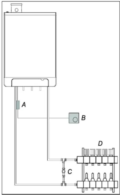
Underfloor heating without pump
Connect the underfloor heating system (D) and set the maximum CH supply temperature of the CH boiler to the design condition. Fit a clamp thermostat (A) onto the supply tube underneath the CH boiler. The clamp thermostat with blind cap must be set to a maximum supply temperature of 55^ C.
Fit the on/off room thermostat (B) and connect in a series with the clamp thermostat. The boiler must be connected to X4 - 6/7.
In this situation, the pump in the boiler is used to bridge the loss of pressure of the underfloor heating system. Using the loss of pressure graph par. 7.4, the maximum loss of pressure of the underfloor heating system can be determined.
Make sure there is a minimal water circulation. See par. 7.3.
In case of an underfloor heating system without pump, we recommend changing the following parameter settings:
par. o from 0 to 3.
par. P from 5 to 2.
Parameter 3 must also be set to its minimum level, or the
Transmission loss of the property, see par. 7.3.
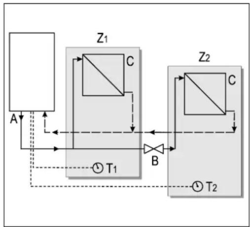
5.1.3 Dividing CH installation in groups in case of additional heat sources
Operating principle
If the room thermostat switches off the boiler because another heat source, the other rooms may cool down.
This can be resolved by splitting the CH installation into two groups. The group with the external heat source (Z2) can be shut off from the main circuit by means of an electrical shut-off valve. Both groups are fitted with their own room thermostat.
Please note: This "external heat source" regulation may only be applied if no extra external boiler has to be heated up (installation type 1).
Installation instructions
- Install the valve in accordance with the connection diagram.
- Connect the room thermostat of group 1 to op X4 - 6/7.
- Connect the room thermostat of group 2 to op X4 - 11/12.
- Change parameter A (see Parameter settings via the service code par. 7.2).
Please note: The room thermostat in group 1 MUST be an on/off thermostat. The room thermostat in group 2 may be an OpenTherm thermostat or an on/off thermostat.
flowchart
graph TD
    A["Component A"] -->|Input| Z1["Component Z1"]
    Z1 -->|Control| B["Component B"]
    B -->|Output| Z2["Component Z2"]
    Z2 -->|Feedback| Z1
    Z1 -->|Feedback| A
    Z2 -->|Feedback| A
    Z1 -->|Feedback| T1["T1"]
    Z2 -->|Feedback| T2["T2"]
Connection diagram "external heat source" regulation
A. CH boiler
B. Electrical shut-off valve 230 V \~
C. Radiators
T1. Room thermostat group 1
T2. Room thermostat group 2
Z1. Group 1
Z2. Group 2
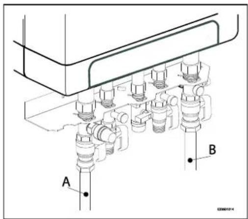
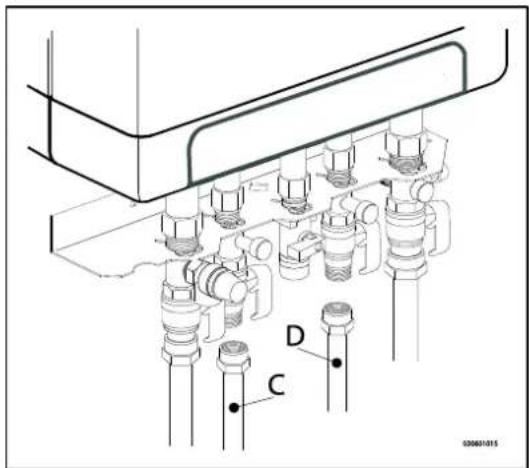
5.2 Connecting DHW installation
- Rinse the installation carefully.
- If required, assemble an inlet combination.
- Assemble the cold (D) and warm water pipe (D) to the connection set.
Comments
- If the unit is only used for warm water supply, the heating function can be switched off using the service code on the operating panel. The CH installation does not need to be connected or filled.
- If the unit is switched off during winter, and is disconnected from the electricity supply, the sanitary water must be drained in order to prevent freezing. To do so, disconnect the tap water connections straight underneath the unit.
In case of old installations or domestic hot water circuits which can contain small particles, install a filter in the domestic hot water circuit.
This pollution could cause a fault during domestic hot water operation.
Resistance graph tap circuit unit
A. EKOMBG22ABV1
B. EKOMBG28ABV1
C. EKOMBG33ABV1
X. Water pipe pressure (Bar)
Y. Flow rate (L/min, tolerance ± 10%)
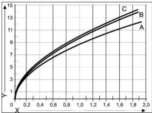
line
| X | A | B | C | | ---- | ---- | ---- | ---- | | 0.0 | 1.0 | 1.0 | 1.0 | | 0.2 | 3.0 | 3.5 | 4.0 | | 0.4 | 5.0 | 6.0 | 7.0 | | 0.6 | 7.0 | 8.5 | 10.0 | | 0.8 | 9.0 | 11.0 | 12.5 | | 1.0 | 10.5 | 12.5 | 14.0 | | 1.2 | 11.5 | 13.5 | 15.0 | | 1.4 | 12.5 | 14.5 | 16.0 | | 1.6 | 13.5 | 15.5 | 17.0 | | 1.8 | 14.5 | 16.5 | 18.0 | | 2.0 | 15.5 | 17.5 | 19.0 |5.3 Connecting electronically

CAUTION
A socket with safety ground must be no further than 1 meter from the unit.
The socket must be easily accessible.
When installing the unit in a damp space, a fixed connection is obligatory, by means of an all-pole main switch with a minimum contact gap of 3 mm.
If the mains cable is damaged or requires replacement for any other reason, the replacement mains cable must be ordered from the manufacturer or its representative. In case of any doubt, contact the manufacturer or its representative.
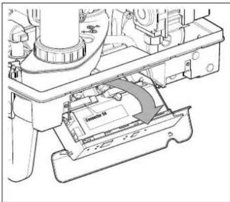
- Remove the plug from the socket, when working on the electrical circuit.
- If there is a cover plate (A), remove it to the front.
- Unscrew both screws (1) behind the display window.
- Slide the bottom of the front panel (2) forwards, and remove it.
- Pull the boiler controller forward. The boiler controller unit will tip downwards in the process.
- Consult par. 9.2 to make the connections.
- After the required connections have been made, slide the boiler controller back into the unit and return the cover plate, if you are using one.
- After making the required connections, connect the unit to the socket with safety ground.
natural_image
Technical line drawing of a mechanical assembly with labeled component A (no text or symbols beyond label)
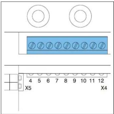
5.3.1 Electrical connections
| Temperature regulation | Connector X4 | Comments |
| Room thermostat on/off | 6 - 7 | |
| Modulating thermostat with comfort function in use | 11 - 12 | |
| Outdoor temperature sensor | 8 - 9 | |
| Frost thermostat | 6 - 7 | Parallel over room thermostat |
5.4 Connect room thermostat
5.4.1 Room thermostat on/off
- Connect the room thermostat (see par. 10.1).
- If necessary, set the feedback resistance of the room thermostat to 0.1 A. If unsure, measure the electrical current and set it accordingly.
The maximum resistance of the thermostat pipe and the room thermostat amounts to a total of 15 Ohm.
5.4.2 Modulating room thermostat, Open Therm

The unit is suitable for connecting a modulating room thermostat, in accordance with the OpenTherm communication protocol.
The most important function of the modulating room thermostat is to calculate the input temperature at a required room temperature, in order to make optimal use of the modulating. At every heating request, the required input temperature is shown on the display of the unit.
Connect the modulating thermostat (see par. 10.1).
If you want to use the tap water on/off switch function of the OpenTherm thermostat, the tap water comfort function must be set to eco or on.
For more information, consult the manual of the room thermostat.
5.4.3 Modulating room thermostat, wireless

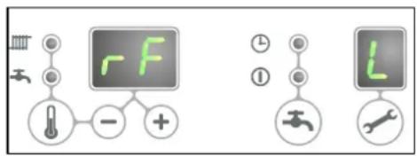
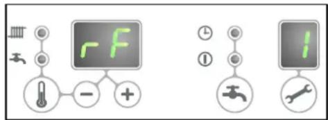
rf-module
The EKOMBG*ABV1 CH boiler is suitable to communicate wireless without sending/receiving module with the Honeywell room thermostats T87RF1003 Round RF, DTS92 and CMS927. The CH boiler and the room thermostat must be appointed to each other:
- Press the reset ↩ button of the unit for approximately 5 seconds to access the RF room thermostat menu.
- One of the following codes will be shown on the display of the unit:
-
rF and L / - : the display above the ✅ button shows an L alternated by a - red led : flashing
The CH boiler has not been appointed. A unit in this operating status, can be linked by using the method of the appropriate room thermostat.
The method of appointment depends on the type of room thermostat and is described in the installation and operating instructions of the wireless room thermostat. -
rF and L / 1 : the display above ✏ button shows an L alternated by a 1 red led : off
The CH boiler has already been appointed. There is already an existing link with an RF room thermostat. In order to allow a new link to be made, the existing link will have to be removed.
See: Undo the appointment of an RF room thermostat to the CH boiler.
- Press the reset ⏻ button to leave the RF room thermostat menu or wait for 1 minute.
Testing the connection between the unit and the RF room thermostat
- Press the reset button of the unit for approximately 5 seconds to access the RF room thermostat menu of the boiler controller.
- Press the service ✏ button 1x. On the display above the ✏ button, a t will be shown.
- Set the room thermostat to the test mode (see the installation and operating instructions of the room thermostat).
- The red led above the reset ⏻ button will flash if the appointment has been carried out correctly.
- Press the reset button of the unit to leave the RF room thermostat menu of the boiler controller. You will automatically exit the test mode 1 minute after the last test message of the RF room thermostat has been received.
Undo the appointment of an RF room thermostat to the CH boiler.
- Press the reset button of the unit for approximately 5 seconds to access the RF room thermostat menu of the CH boiler.
- Press the service ↗ button 2x. On the display above the ↗ button, a C will be shown.
- Press the reset button of the unit again to remove the existing appointments. The display of the unit will show rF again, with a flashing L / - . If required, an RF room thermostat can be appointed to the unit again.
- Press the reset ⏻ button of the unit to leave the RF room thermostat menu or wait for 1 minute.
5.4.4 Outdoor temperature sensor
The unit is provided with a connection for an outdoor temperature sensor. The outdoor temperature sensor should be used in combination with an on/off room thermostat.
In principle, any on/off room thermostat can be combined with an outdoor sensor. Upon request of the room thermostat, the boiler will provide heat until the maximum set temperature in the boiler has been reached. This maximum set temperature is automatically regulated via the outdoor sensor, in accordance with the set fuel line in the boiler.
Connect the room outdoor sensor (see par. 10.1).
For the fuel line setting, see the weather dependent regulation (see par. 7.5).
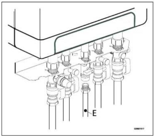
5.5 Connecting gas
- Fit the gas valve directly on the 1/2" gas connection of the connection set using appropriate seal
- .Place a gas sieve in the connection for the unit if the gas may be contaminated.
- Connect the gas pipe in the gas valve using appropriate seal..
- Check the gas carrying parts for leakages at a pressure of up to 50 mbar.
- The gas pipe should be fitted pressure free.
natural_image
Technical diagram of a mechanical assembly with multiple cylindrical components and a labeled point E (no text or symbols beyond label)5.6 Flue and air supply duct

For the installation of the flue and air supply duct material, see the manual included with the materials. Contact the manufacturer of the relevant flue and air supply duct materials for extensive technical information and specific assembly instructions.

Make sure that the socket connections of the flue and air supply duct materials are correctly sealed.
Improper fastening of the flue and the air supply duct can lead to hazardous situations or result in personal injury. Check all flue components for tightness.
Don not use screws or parkers to mount the flue system as leakage ca occur.
Do not use any sort of grease when mounting the pipe system. Use water instead. The sealing rubbers can be negatively affected whe grease is applied.
Do not mix any components, materials or ways of coupling from different manufacturers.
5.6.1 Concentric connection 60/100
The boiler is fitted with a flue gas adapter suitable for connecting to a concentric flue gas extractor system with a diameter of 60/100.
Fit the concentric pipe thoughtfully in the adapter. The built in gaskets ensure there is an air tight seal.
5.6.2 Concentric connection 80/125
If required, the flue gas adapter 60/100 can be replaced by a version for a flue gas extractor system with a 80/125 diameter.
- Carefully follow the instruction as provided with the adapter set 80/125.
- Fit the concentric pipe thoughtfully in the adapter. The built in gaskets ensure there is an air tight seal.
5.6.3 Parallel connection 80/80
If required, the flue gas adapter 60/100 can be replaced by a version for a parallel flue system (2 pipes) with a 80 mm diameter.
- Carefully follow the instruction as provided with the adapter set 80.
- Fit the pipes for the air supply and flue gas thoughtfully in the air inlet opening and flue gas adapter of the unit. The built in gaskets ensure there is an air tight seal. Make sure that the connections are not mixed.
5.7 Outlet systems
Please note that not all flue gas configurations described below are permitted in all countries. Therefore observe local regulations prior to installation.
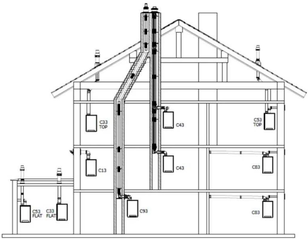
The drawings above are a sample and can differ on details.
| Explanation flue systems | ||
| Category in accordance to CE | ||
| B23 | A flue that evacuates the products of combustion to the outside of the room containing the appliance. The combustion air is drawn directly from the room. | Make sure the air inlet is open and complies to the demands |
| B33 | A flue system which is connected to a common duct system. This common duct system consists of a single natural draught flue. All pressurized parts of the appliance containing products of combustion are completely enclosed by parts of the appliance supplying combustion air. Combustion air is drawn into the appliance from the room by means of a concentric duct, which encloses the flue. The air enters through defined orifices situated in the surface of the duct. | Make sure the air inlet is open and complies to the demands |
| C13 | Horizontal flue system. Discharge in the outside wall.Inlet opening for the air supply is in the same pressure zone as the discharge | For example : a wall terminal through the facede. |
| C33 | Vertical flue system. Flue gas discharge via the roof.Inlet opening for the air supply is in the same pressure zone as the discharge | For example : a vertical roof terminal. |
| C43 | Joint air supply and flue gas discharge duct (CLV system)Twin-pipe or concentric | |
| C53 | Separate air supply and separate flue gas discharge duct.Discharging into different pressure zones | |
| C63 | Free in the market available flue material with CE approval | Do not mix flue materials from different suppliers. |
| C83 | Joint air supply and flue gas discharge duct (CLV system)Discharging into different pressure zones | Only as twin pipe system |
| C93 | Air supply and flue gas discharge duct in shaft or ducted: Concentric. Air supply from existing duct. Flue gas discharge via the roof. Air supply and flue gas discharge are in the same pressure zone. | Concentric flue system between the boiler and the duct. |
5.8 Flue material
The following flue materials can be ordered at Daikin.
Also visit the website: fluegas.daikin.eu
C13
| Art.no. | Description |
| EKFGP2978 | Wall Terminal Kit PP/GLV 60/100 |
| EKFGP4651 | Extension PP/GLV 60/100 x 500mm |
| EKFGP4652 | Extension PP/GLV 60/100 x 1000mm |
| EKFGP4660 | Elbow PP/GLV 60/100 90° |
| EKFGP4661 | Elbow PP/GLV 60/100 45° |
| EKFGP2977 | Wall Terminal Kit low profile PP/GLV 60/100 |
| EKFGP4664 | Elbow PP/GLV 60/100 30° |
| EKFGP4631 | Wall Bracket Dn.100 |
| EKFGP4667 | Measurement Tee with Inspection Panel PP/GLV 60/100 |
C33
| Art.no. | Description |
| EKFGP4631 | Wall Bracket Dn.100 |
| EKFGP4651 | Extension PP/GLV 60/100 x 500mm |
| EKFGP4652 | Extension PP/GLV 60/100 x 1000mm |
| EKFGP4660 | Elbow PP/GLV 60/100 90° |
| EKFGP4661 | Elbow PP/GLV 60/100 45° |
| EKFGP4664 | Elbow PP/GLV 60/100 30° |
| EKFGP4667 | Measurement Tee with Inspection Panel PP/GLV 60/100 |
| EKFGP6837 | Roof Terminal PP/GLV 60/100 AR460 |
C53
| Art.no. | Description |
| EKFGP4651 | Extension PP/GLV 60/100 x 500mm |
| EKFGP4652 | Extension PP/GLV 60/100 x 1000mm |
| EKFGP6837 | Roof Terminal PP/GLV 60/100 AR460 |
| EKFGW4085 | Elbow PP 80 90° |
| EKFGW4086 | Elbow PP 80 45° |
| EKFGV1102 | Chimney Conection Set 60/100 Air Intake Dn.80 C53 |
| EKFGP4660 | Elbow PP/GLV 60/100 90° |
| EKFGP4661 | Elbow PP/GLV 60/100 45° |
| EKFGP4664 | Elbow PP/GLV 60/100 30° |
| EKFGP4667 | Measurement Tee with Inspection Panel PP/GLV 60/100 |
| EKFGP4631 | Wall Bracket Dn.100 |
| EKFGW4001 | Extension PP 80x500 |
| EKFGW4002 | Extension PP 80x1000 |
| EKFGW4004 | Extension PP 80x2000 |
C93
| Art.no. | Description |
| EKFGP4678 | Chimney Connection 60/100 |
| EKFGP1856 | Flex Kit PP Dn.60-80 |
| EKFGP6340 | Extension Flex PP 80 L=10 M |
| EKFGP6344 | Extension Flex PP 80 L=15 M |
| EKFGP6341 | Extension Flex PP 80 L=25 M |
| EKFGP6342 | Extension Flex PP 80 L=50 M |
| EKFGP6324 | Connector Flex-Flex PP 80 |
| EKFGP4664 | Elbow PP/GLV 60/100 30° |
| EKFGP4661 | Elbow PP/GLV 60/100 45° |
| EKFGP4660 | Elbow PP/GLV 60/100 90° |
| EKFGP6333 | Spacer PP 80-100 |
| EKFGP4667 | Measurement Tee with Inspection Panel PP/GLV 60/100 |
| EKFGP4631 | Wall Bracket Dn.100 |
| EKFGP4651 | Extension PP/GLV 60/100 x 500mm |
5.9 Connection to a flue system without air inlet (B23, B33)

CAUTION
- Make sure the boiler room complies to the regulatory requirements for connecting to a flue system in accordance to B23 or B33
- When connection the boiler to a flue system in accordance to B23 or B33 the electrical protection class is IP20 instead of IP44
General assembly
- Slide the combustion gas outlet pipes into each other. From the unit, every pipe has to be slid into the previous one. Mount a non-vertical combustion gas outlet pipe on a slope towards the unit (min. 5mm/m).
5.9.1 Permitted pipe lengths at parallel air supply and flue tube systems
Permitted pipe lengths B23 and B33 when applying ∅80 mm
| C13 | C33 | C43 | C53 | C83 | |
| EKOMBG22ABV1 | 100 m | 100 m | 100 m | 100 m | 100 m |
| EKOMBG28ABV1 | 85 m | 85 m | 85 m | 85 m | 85 m |
| EKOMBG33ABV1 | 80 m | 80 m | 80 m | 80 m | 80 m |
5.10 Connection to a sealed flue system.
5.10.1 Pipe lengths
As the resistance of the flue tube and air supply pipes increases, the power of the unit will decrease. The maximum permitted power reduction is 5%.
The resistance of the air supply and the combustible gas outlet depends on the length, diameter and all components of the pipe system. Per unit category, the total permitted pipe length has been indicated for the air supply and the combustible gas outlet.
5.10.2 Permitted pipe lengths in concentric flue tube systems
Permitted pipe lengths when applying concentric 60/100
| C13 | C33 | |
| EKOMBG22ABV1 | 10 m | 11 m |
| EKOMBG28ABV1 | 10 m | 10 m |
| EKOMBG33ABV1 | 10 m | 10 m |
Permitted pipe lengths when applying concentric 80/125
Contact the manufacturer for test calculations for the resistance of the air supply and combustible gas outlet pipe and the wall temperature at the end of the combustible gas outlet pipe.
Replacement lengths
| Bend 90° | R/D=1 | 2 m |
| Bend 45° | R/D=1 | 1 m |
| Knee 90° | R/D=0.5 | 4 m |
| Knee 45° | R/D=0.5 | 2 m |
General assembly:
For all outlets, the following assembly applies:
- Slide the concentric combustion gas outlet pipe and air supply pipe.
- Slide the concentric pipes into each other.
From the unit, every pipe has to be slid into the previous one. - Mount a non-vertical combustion gas outlet pipe on a slope towards the unit (min. 5mm/m).
- Fit the assembly brackets in accordance with the assembly instructions of the supplier of the air supply/flue tube system.
5.10.3 Permitted pipe lengths at parallel air supply and flue tube systems
Permitted pipe lengths when applying ∅80 mm (total of flue pipe and air intake pipe together).
| C13 | C33 | C43 | C53 | C83 | |
| EKOMBG22ABV1 | 100 m | 100 m | 100 m | 100 m | 100 m |
| EKOMBG28ABV1 | 85 m | 85 m | 85 m | 85 m | 85 m |
| EKOMBG33ABV1 | 80 m | 80 m | 80 m | 80 m | 80 m |
Replacement lengths
| Bend 90° | R/D=1 | 2 m |
| Bend 45° | R/D=1 | 1 m |
| Knee 90° | R/D=0.5 | 4 m |
| Knee 45° | R/D=0.5 | 2 m |
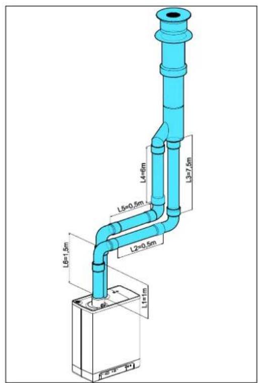
Calculation example
| Pipe | Pipe lengths | Pipe length total |
| Flue gas outlet | L1 + L2 + L3 + 2x2 m | 13 m |
| Air supply | L4 + L5 + L6 + 2x2m | 12 m |
Note:
The total pipe length is: sum of the straight pipe lengths + sum of the replacement pipe lengths of bends/knees amounts to a total of 25 meters. If this value is less than the maximum permitted pipe length, the flue gas outlet meets the requirements on this point.

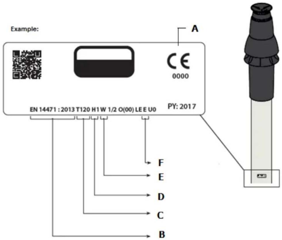
5.10.4 Free in the market available flue gas materials (C63).
The properties of the combustion determine the choices for the flue material.
The standards EN 1443 and EN 1856-1 provide the necessary information for choosing the flow material by means of a sticker including an identification string.
The Identification string contains the following information:
A CE marking
B The standard to comply to: Metal, EN 1856-1 or EN 1856-2
Plastic, EN 14471
The ID string needs to contain the following information:
C Temperature class : T120
D Pressure class : Pressure (P) or High Pressure (Hi)
E Resistance class : W (Wet)
F Resistance class in case of fire : E
Dimensions C63 Flue system (external dimensions in mm)
| Parallel | Concentric 80/125 | Concentric 60/100 | |||
| Flue pipe | Air inlet | Flue pipe | Air inlet | ||
| 80 | +0,3-0,7 | 80 | +0,3-0,7 | 60 | +0,3-0,7 |

Flue materials of different markings must not be combined!
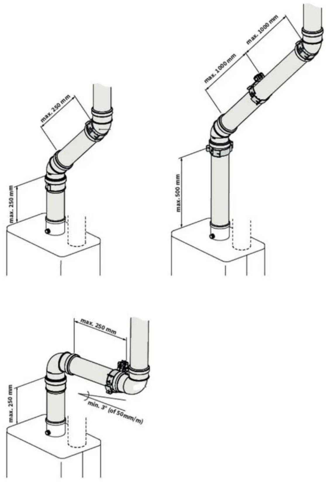
5.10.5 Securing the flue system

IMPORTANT
• These regulations are typical for both concentric and parallel flue systems.
- The flue system must be secured to a solid structure.
- The flue system should have a continuous fall back to the boiler (1.5° to 3°). N.B. Wall terminals must be installed leveled..
- Only use accompanying brackets.
- Every elbow must be secured by using the bracket.
Exception at connecting on boiler: If the length of the pipes before and aft the first elbow, are no more than 250 mm, the second element after the first elbow has to contain a bracket.
Note: The bracket must be positioned on the elbow!
- Every extension must be secured per metre with a bracket.
This bracket must not be clamped around the pipe ensuring free movement of the pipe..
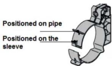
- Make sure bracket is locked into the correct position depending on the position of the bracket on the pipe or elbow:
- Do not mix flue parts or clamps of different suppliers.
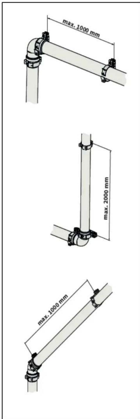
Max. distance between clamps
| Vertical | Others |
| 2000 mm | 1000 mm |
- Divide the lengths between the brackets evenly.
• Every system must contain at least 1 bracket.
• Position the first clam at a maximum of 500 mm from the boiler.
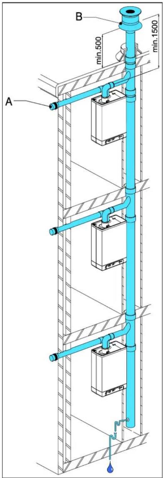
5.10.6 Air supply from the facade and a roof outlet with communal exhaust system
Unit category: C83

IMPORTANT
- An air supply from the outside wall and a roof outlet with a combined flue system is allowed.
- The air supply in the facade must be fitted with an inlet grid (A).
- The combined flue system must be fitted with a traction extractor hood (B).
- If the combined flue system is situated in the outdoors, the output pipe must be double-walled or insulated.
The minimum diameters of the communal output system based on vacuum
| Flue tube diameter | |||
| EKOMBG*ABV1 | |||
| Number of units | 22 | 28 | 33 |
| 2 | 110 | 130 | 130 |
| 3 | 130 | 150 | 150 |
| 4 | 150 | 180 | 180 |
| 5 | 180 | 200 | 200 |
| 6 | 200 | 220 | 220 |
| 7 | 220 | 230 | 230 |
| 8 | 230 | 250 | 250 |
| 9 | 240 | 270 | 270 |
| 10 | 260 | 280 | 280 |
| 11 | 270 | 290 | 290 |
| 12 | 280 | 300 | 300 |
Communal combustible gas outlet
The output of the combustion gas outlet can be made in any location on the sloping roof surface, providing the outlet in the roof surface has the same orientation as the air supply in the facade. On a flat roof, the outlet of the combustion gas outlet must be made in the "free" outlet area.
Fit a condense output.
Note
The communal outlet is certified in combination with the unit.
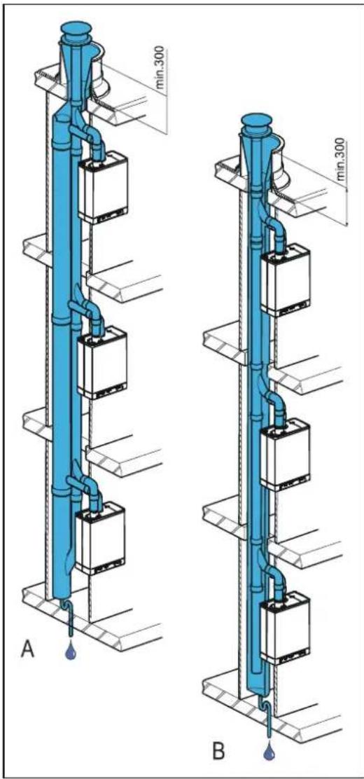
5.10.7 Combined flue outlet/air inlet system
Unit category : C43

IMPORTANT
• A Combination Air/flue gas system is permitted.
- For the combined combustion gas outlet hood and air supply hood, a declaration of no objection or a Gas certificate from the Gastec Gas institute is required.
- The passage of the pressure balancing opening at the bottom of the communal air supply and flue gas outlet system is equal to 0.44 times the flue gas outlet surface.
The communal air supply and the communal output of the combustion gases may be carried out concentrically or separately.
The minimum diameters of the combined air supply and flue system based on the continuation sheet 2001-02 inspection requirements no, 138 of Gastec.
| EKOMBG22ABV1 AND EKOMBG28ABV1 | EKOMBG33ABV1 | |||||||
| Number of units | Concentric | Parallel | Concentric | Parallel | ||||
| Flue outlet | Air inlet | Flue outlet | Air inlet | Flue outlet | Air inlet | Flue outlet | Air inlet | |
| 2 | 135 | 253 | 135 | 214 | 155 | 291 | 155 | 246 |
| 3 | 157 | 295 | 157 | 249 | 166 | 311 | 166 | 263 |
| 4 | 166 | 311 | 166 | 263 | 176 | 330 | 176 | 279 |
| 5 | 175 | 328 | 175 | 278 | 186 | 349 | 186 | 295 |
| 6 | 184 | 345 | 184 | 292 | 196 | 367 | 196 | 311 |
| 7 | 193 | 362 | 193 | 306 | 206 | 386 | 206 | 326 |
| 8 | 201 | 376 | 201 | 318 | 216 | 404 | 216 | 342 |
| 9 | 210 | 393 | 210 | 332 | 226 | 423 | 226 | 358 |
| 10 | 219 | 410 | 219 | 347 | 236 | 442 | 236 | 374 |
| 11 | 228 | 427 | 228 | 361 | 247 | 463 | 247 | 391 |
| 12 | 237 | 444 | 237 | 375 | 257 | 482 | 257 | 407 |
| 13 | 246 | 461 | 246 | 389 | 267 | 500 | 267 | 423 |
| 14 | 255 | 478 | 255 | 404 | 277 | 519 | 277 | 439 |
| 15 | 264 | 494 | 264 | 418 | 287 | 538 | 287 | 454 |
| 16 | 272 | 509 | 272 | 431 | 297 | 556 | 297 | 470 |
| 17 | 281 | 526 | 281 | 445 | 307 | 575 | 307 | 486 |
| 18 | 290 | 543 | 290 | 459 | 317 | 594 | 317 | 502 |
| 19 | 299 | 560 | 299 | 473 | 328 | 614 | 328 | 519 |
| 20 | 308 | 577 | 308 | 488 | 338 | 633 | 338 | 535 |
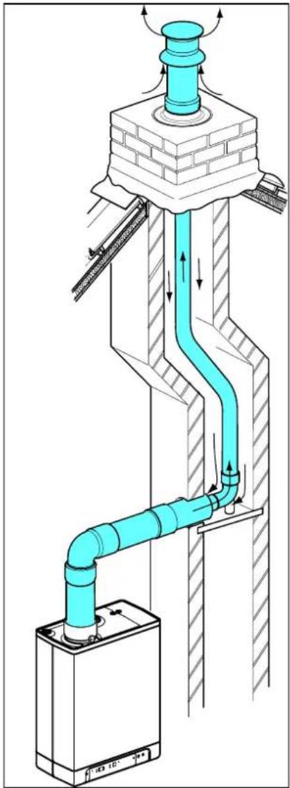
5.10.8 Concentric horizontal flue gas outlet, vertical part air-surrounded by shaft
Unit category : C93
A flue tube system according to C93 (C33) is permitted when using CE approved flue material or the flue material provided by Daikin.
The ponts below have to be considered.
General
- Flue outlet in shaft with 60 or 80 mm diameter (rigid or flexible).
- When using plastic flue pipe materials, a minimum temperature class of T120 applies.
- The transfer bend between concentric and vertical flue connection in the shaft must be supported in accordance with supplier instructions. The assembly instruction of the manufacturer for the flue system must always be followed in full.
- In existing installations, the shaft must be inspected and if necessary cleaned before the new installation is commissioned.
- The tightness of the shaft towards living spaces must be ensured.
Permitted pipe length and system requirements
When a shaft (e.g.a brickwork chimney) has the purpose of air intake the following requirements are applicable.
| Flue gas pipe | Dimension shaft [mm] | Max. length [mtr] | |
| Diameter (mm)(rigid or flexible) | Square | Round | |
| DN 60 | 115 x 115 | 135 | 11 |
| DN 80 | 135 x 135 | 155 | 29 |
Note:
The outlet system is certified in combination with the unit.
natural_image
Technical diagram of a pipe system with airflow indicators and structural components (no text or symbols)6 COMMISSIONING THE UNIT AND THE INSTALLATION
6.1 Filling and air purge of unit and installation
6.1.1 CH system
- Insert the unit's plug into a socket.
The unit may carry out a self-check: 2 (on service display). The unit will then go into the off setting: - (on service display) and the CH pressure is shown on the temperature display.

In case of a CH pressure lower than 0.5 bar, the CH pressure will be displayed flashing on the display. In the off setting, the CH pressure will be displayed.
- Connect the filling hose to the fill/drain tap and fill the installation with clean drinking water, up to a pressure between 1 and 2 bar if the installation is cold (to be read from the temperature display).
- Aerate the system with the manual aerator (A). Upon request, an automatic aerator can be fitted onto the unit instead of the manual aerator.
- Aerate the installation with the manual aerators on the radiators.
- Top up the CH installation if the pressure has dipped too low due to the aeration.
- Check all couplings for leaks.
- Check whether the siphon is filled with water.

WARNING
If the siphon is not filled with water, combustion gases may be released into the room.

WARNING
If an additive is added to the CH water, it must be suitable for the materials used in the unit, such as copper, brass, stainless steel, steel, plastic and rubber. The additive should preferably have a KIWA/ATA/Atest certification.
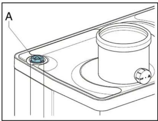
natural_image
Technical line drawing of a mechanical component with labeled point A (no text or symbols beyond label)6.1.2 DHW provision
- Open the main tap to bring the DHW section up to pressure.
- Aerate the exchanger and the pipe system by opening a DHW tap. Leave the tap open until all air has flowed out of the system.
- Check all couplings for leaks.
6.1.3 Gas supply
- Aerate the gas pipe with the initial pressure measuring nipple (D) on the gas block.
- Check all couplings for leaks.
- Check the initial pressure and offset pressure (see par. 7.7).
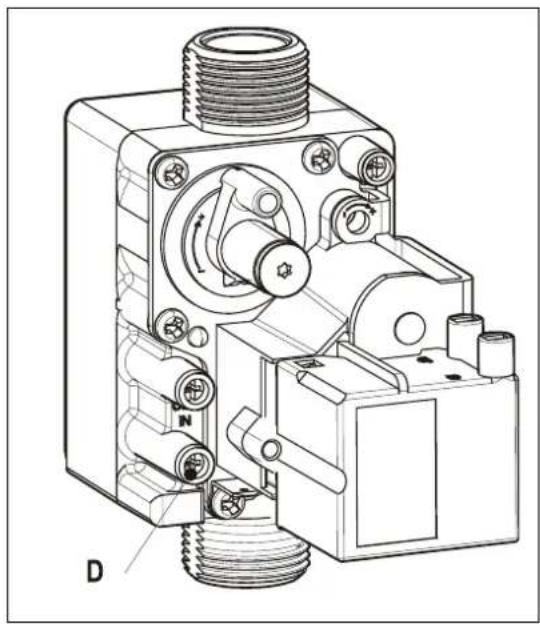
natural_image
Technical line drawing of a mechanical device with threaded ports and internal components (no text or symbols)6.2 Commissioning the unit
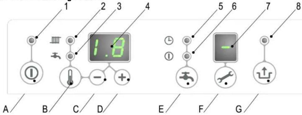
Reading
1 On/off
2 CH operation or setting maximum CH temperature
3 Tap operation or setting tap temperature
4 Required temperature CH or tap water in °C / pressure CH water in bar / malfunction code
5 Tap comfort function eco
6 Tap comfort function on
7 Operating code
8 Flashing in case of a malfunction
Operating
A On/off button
B Tap/CH button to set the required temperature
C - button
D + button
E Tap comfort function off / eco / on button
F Service button / actual temperature during heat request
G Reset button
After the following actions have been completed, the unit may be commissioned.
- Press the Ⓐ button to commission the unit.
The heat exchanger will be heated up, and on the service ✏ display, 3, 4 and 7 appear (Depending on status of external eco switch and/or OpenTherm regulation). - Set the pump setting depending on the set maximum power and the water side resistance of the installation. For the water head of the pump and the loss of pressure of the unit: (see par. 7.4).
- Set the room thermostat higher than the room temperature. The unit will now go into CH operation: 5 on the service ✗ display.
- Fire up the installation.
- Check whether the set maximum CH power matches the requested value. If necessary, the maximum CH power can be adjusted (see par. 7.2 parameter c and 3 and par. 7.3)
- Check whether the set minimum and maximum value of the pump characteristic have been set correctly (see par. 7.2 and parameter 3. and c. and par. 7.4)
- Switch the unit off.
- Purge the air from the unit and the installation after cooling down (top up if necessary).
- Switch the unit on.
- Check the heating and the hot water provision for the correct functioning.
- Instruct the user on the filling, air purging and functioning of the heating and the hot water provision.
Comments
- The unit is fitted with an electronic boiler controller which ignites the boiler controller and controls she modulating pump, at every heat request from the heating or from the hot water provision.
- The circulation pump will run at every heat request for the heating. The pump has a post-running time of 1 minute. The post-running time can be changed upon request (see par. 7.2).
- The pump will run automatically 1 time per 24 hours, for 10 seconds, in order to prevent it from getting stuck. This automatic switching on of the pump takes place 24 hours after the lastheating request. To change the time, the room thermostat must be turned up for a moment at the requested time.
- For the hot water provision, the pump will not run.
6.3 Switching off the unit

CAUTION
Drain the unit and the installation, if the mains electricity supply is interrupted and there is a risk of freezing.
- Remove the plug from the socket.
- Drain the unit with the filling/draining tap.
- Drain the installation at the lowest point.
- Close the main tap of the hot and cold water supply to the unit.
- Drain the unit by loosening the domestic hot water couplings under the unit.
- Empty the siphon.
6.3.1 Frost protection
- In order to prevent the condense outlet from freezing, the unit must be installed in a frost-free room.
- The unit is fitted with frost protection in order to prevent it from freezing. If the temperature of the heat exchanger drops too low, the boiler will switch on until the heat exchanger has heated up. If there is the possibility that the installation (or a part thereof) may freeze, an (external) frost thermostat must be fitted at the coldest place, on the return pipe. This must be connected in accordance with the electrical diagram (see par. 9.2).
Note
If an (external) frost thermostat has been fitted on the installation and has been connected to the unit, it will not be active if the unit on the operating panel is switched off ( - on service display).
7 SETTING AND ADJUSTMENT
The functioning of the unit can be influenced by means of the (parameter) settings in the boiler controller. Part of this can be configured directly via the operating panel, another part can only be adjusted by means of the service code.
7.1 Direct via operating panel
The following functions can be operated directly.
Unit on/off
The Ⓑ button activates the unit.
When the unit is active, the green LED above the Button will be lit. When the unit is off, one bar will be lit on the service display ( - ) to show the unit is connected to the electricity supply. In this operation setting, the temperature display will also show the pressure in the CH installation (in bar).
Summer mode.
When parameter q is set to a value unlike 0 summer mode can be activated pressing the Ⓐbutton.
In Summer mode the central heating has been shut off while DHW remains active.
Summer mode can be activated by pressing the ① button. again after activating the boiler.
On the display [So], [Su] or [Et] appears (the code on the display depends on the setting of parameter q).
Summer mode can be deactivated by pressing the ① button twice. The boiler will then be in normal functional mode again.
Tap comfort
The tap comfort function can be operated with the tap comfort 🔊 button and has the following settings:
- On: (① LED on) The tap comfort function of the unit is continuously switched on. The heat exchanger is continuously kept warm. The unit always immediately provides warm water.
- Eco: ( ⊕ LED on) The tap comfort function of the unit is self-learning. The unit will adjust to the usage pattern of the domestic hot water. This means the heat exchanger will not be kept warm during the night or during longer absences.
- Off: (Both LEDs off.) Off: The heat exchanger is not kept warm which means the supply of domestic hot water takes a bit of time. If there is no desire for domestic hot water, or of immediate supply hereof, the tap comfort function can be switched off.
Resetting
Check the nature of the malfunction on the basis of the malfunction codes under par. 8.2 and if possible, resolve the cause of the malfunction before resetting the unit.
If a locking malfunction is indicated by means of a flashing LED above the button and a number on the ↓ display, the unit can be restarted by pressing the reset ↓ button.
Change settings of the various functions:
Pressing the 📁 button for 2 seconds, will take you to the users setting menu (LED at 📄 and the number display will start to flash). If you press the 🔊 button repeatedly, a different function LED will flash each time. When the LED flashes, the appropriate function can be set with the + and - button. The set value is displayed on the display.
The on/off button closes the settings menu and the changes are not saved.
The reset button closes the settings menu and saves the changes.
When no button is pressed for 30 seconds, the settings menu will automatically be closed and the changes are saved.
Maximum CH leaving water temperature
Press the button until the LED at starts flashing.
Use the + and — button to enter the temperature between 30^ C and 90^ C (standard setting 80^ C).
Tap water temperature
Press the button until the LED at starts flashing.
Use the + and — button to enter the temperature between 40°C and 65°C (standard setting 60°C).
7.2 Parameter settings via the service code
The parameters of the boiler controller have been configured in the factory in accordance with the following table.
These parameters can only be changed with the service code. Take the following actions to activate the program memory:
-
Press the ↗ and the ↓ button simultaneously, until a □ appears on the service display and a □ on the temperature display.
-
Use the + button to enter 15 (service code) on the temperature display.
-
Use the ✕ button to set the parameter you wish to configure, on the service display.
-
Use the + and - button to set the parameter to the required value (visible) on the temperature display.
-
After all the required changes have been entered, press the ↕button until P appears on the service display.
The boiler controller has now been reprogrammed.
Note
Pressing the ① button will take you out of the menu without saving the parameter changes.
Example: Change maximum CH power
- Press the ↗ and the ↓ button simultaneously.
- Use the +button to go to 15
- Press the ✕ button 3 x. 60 and 3 will appear on the display.
- Use the + button to change the 60 to 70.
- Press the ↕ button until P appears.
- The change has now been implemented. The maximum CH power has been increased from 60 to 70 %.
| EKOMBG*ABV1 | |||||
| Parameter | Description | 22 | 28 | 33 | Settings reach |
| 0 | Service code [15] | - | - | - | Access to installers settings, the service code must be entered (=15) |
| 1 | Installation type | 0 | 0 | 0 | 0= Combi1= Space heating + hot water by means of storage tank2= Tap (hot water only)3= Solo |
| 2 | CH pump setting | 0 | 0 | 0 | 0= pump post-running time active1= pump continuously active2 - 5 = Not active |
| 3 | Set maximum CH power | 60 | 60 | 60 | Setting reach set value parameter c up to 100% (100 % = 99 + 1x) |
| 3. | Maximum capacity modulating CH pump | 80 | 80 | 80 | Setting reach set value parameter c. up to 100% |
| 4 | Set maximum hot water power | 99 | 99 | 99 | Setting reach set value parameter d up to 100% |
| 5 | Min. leaving water temperature of the fuel line | 25 | 25 | 25 | Setting reach 10°C to set value parameter 5 |
| 5. | Max setting value leaving water temperature via operating panel | 90 | 90 | 90 | Setting reach 30°C to 90°C |
| 6 | Min. outdoor temperature of the fuel line | -7 | -7 | -7 | Setting reach -30 to 10°C |
| 7 | Max. outdoor temperature of the fuel line | 25 | 25 | 25 | Setting reach 15°C to 30°C |
| 8 | CH pump post-running time after CH operation | 1 | 1 | 1 | Setting reach 0 to 15 minutes |
| 9 | CH pump post-running time after boiler operation | 1 | 1 | 1 | Setting reach 0 to 15 minutes (n/a to Combi unit) |
| A | Setting three-way valve or electrical valve | 0 | 0 | 0 | 0= powered during CH operation1= powered during hot water operation and rest2= powered during every heat request (CH, hot water and continuous heating function)3= group regulation4 and higher = Not applicable |
| b | Booster | 0 | 0 | 0 | Not applicable |
| C | Step-by-step modulation | 1 | 1 | 1 | 0= step-by-step modulation off during CH operation1= step-by-step modulation on during CH operation2= Power control by Open Therm room thermostat enabled |
| C | Minimum rpm CH | 30 | 30 | 30 | Setting reach 20 to 50% |
| c. | Minimum capacity modulating CH pump | 40 | 40 | 40 | Setting reach 15 to set value par. 3. |
| D | Minimum rpm hot water | 25 | 25 | 25 | Setting reach 20 to 50% |
| E | Min. leaving water temperature at OT (OpenTherm) or RF thermostat | 30 | 30 | 30 | Setting reach 10°C to 60°C |
| E. | Reaction OT and RF room thermostat | 1 | 1 | 1 | 0= do not respond to hot water request if requested temperature is lower than the set value par. E1= respond to hot water request with minimum leaving water temperature limited to set value par. E2= respond to hot water request with maximum leaving water temperature (on/off function) |
| F | Start rpm CH | 70 | 60 | 50 | Settings reach 40 to 99% of the set maximum rpm |
| F. | Minimum start rpm hot water | 70 | 60 | 50 | Settings reach 40 to 99% of the set maximum rpm |
| h | Max. rpm fan | 50 | 50 | 50 | Setting reach 40 to 50 (40=4000 rpm, 50=5000 rpm). Please note: Factory setting, rpm may deviate |
| J | Not applicable | - | - | - | Not applicable |
| L | Legionella protection | 0 | 0 | 0 | Not applicable (only for boilers with external DHW tank) |
| N | Regulated temperature during boiler operation (Ta) | 80 | 80 | 80 | Setting reach 60°C to 90°C |
| n. | Hot water temperature at Comfort/Eco | 0 | 0 | 0 | Setting reach 0 or 40°C to 60°C0 = reheating temperature is equal to hot water temperature |
| O. | Wait time CH request response | 0 | 0 | 0 | Settings reach 0 – 15 minutes |
| O | Waiting time CH operation after hot water operation | 0 | 0 | 0 | Settings reach 0 to 15 minutes |
| o. | Number of eco days | 3 | 3 | 3 | Setting reach 0,1 to 100 = Comfort function controllable by Open Therm room thermostat1 – 10 number of eco days |
| P | Anti-recycling time during CH operation | 5 | 5 | 5 | Minimum switch off time on boiler water temperature Can be set to 0 to 15 minutes |
| P. | Reference value hot water | 24 | 30 | 36 | 24 = EKOMBG22ABV130 = EKOMBG28ABV136 = EKOMBG33ABV1 |
| q | Summer mode | 0 | 0 | 0 | 0 = Summer mode deactivated1 = Summer mode to be activated by 1button(code in display : Su)2 = Summer mode to be activated by 1button(code in display : So)3 = Summer mode to be activated by 1button(code in display : Et) |
| r | Heating curve coefficient | 0 | 0 | 0 | Not active |
7.3 Setting maximum CH power
The maximum CH power is set to 60% in the factory. If more power is required for the CH installation, the maximum CH power can be changed by adjusting the rpm of the fan. See table: Setting CH power.
This table shows the relation between the rpm of the fan and the unit power.
| Desired CH power in kW (approx.) | Settings on service display(in % maximum rpm) | ||
| EKOMBG*ABV1 | |||
| 22 | 28 | 33 | |
| 22.7 | 28.4 | 31.9 | 100 |
| 20.5 | 25.6 | 28.8 | 90 |
| 18.2 | 22.9 | 25.6 | 80 |
| 16.0 | 20.1 | 22.4 | 70 |
| 13.7 | 17.4 | 19.2 | 60 |
| 11.5 | 14.6 | 16.0 | 50 |
| 9.3 | 11.8 | 12.8 | 40 |
| 5.9 | 7.7 | 8.0 | 25 |
Caution:
The power is slowly increased when the fire is lit and is lowered when the set leaving water temperature is reached (modulation on Tsupply).
| The minimum feedthrough amount (l/h) | Set power (kW) |
| 155 | 5.4 kW |
| 240 | 8.5 kW |
| 510 | 17.8 kW |
| 750 | 26.2 kW |
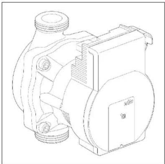
7.4 Set pump capacity
The EKOMBG*ABV1 CH boilers are fitted with a modulating A-class pump which modulates on the basis to the CH power provided. The minimum and maximum capacity of the pump can be adjusted with the parameters 3 and c. Also see par. 7.2. The set value of parameter 3. (max. pump setting) is the percentage of the maximum pump capacity and is linked to the set maximum CH power as set with parameter 3
The set value of parameter c. (min. pump setting) is linked to the minimum CH-power as set with parameter c
If the CH load modulates between the minimum and maximum value, the pump capacity will modulate along proportionately.
Pressure loss graph unit CH side
A. EKOMBG22ABV1
B. EKOMBG28ABV1
C. EKOMBG33ABV1
7.5 Weather dependent regulation
When connecting an outdoor sensor, the leaving water temperature is automatically regulated dependent on the outdoor temperature, in accordance with the set fuel line.
The maximum leaving water temperature (Tmax) is set via the temperature display. If so desired, the fuel line can be changed by using the service code (see par.7.2). The weather dependent regulation only functions with an on-off thermometer. When applying an Open Therm room thermostat, the outside temperature is passed on, but the fuel line of the CH boiler is not active.
Fuel line graph
X. T outside in °C
Y. T leaving water in °C
A. Factory setting
$$ \left(\text {Tmax} \mathrm{CH} = 8 0 ^ {\circ} \mathrm{C}, \text {Tmin} \mathrm{CH} = 2 5 ^ {\circ} \mathrm{C}, \text {Tmin} \mathrm{ex} = - 7 ^ {\circ} \mathrm{C}, \text {Tmax} \mathrm{ex} = 2 5 ^ {\circ} \mathrm{C}\right) $$
natural_image
Technical line drawing of a mechanical pump or motor assembly (no text or symbols)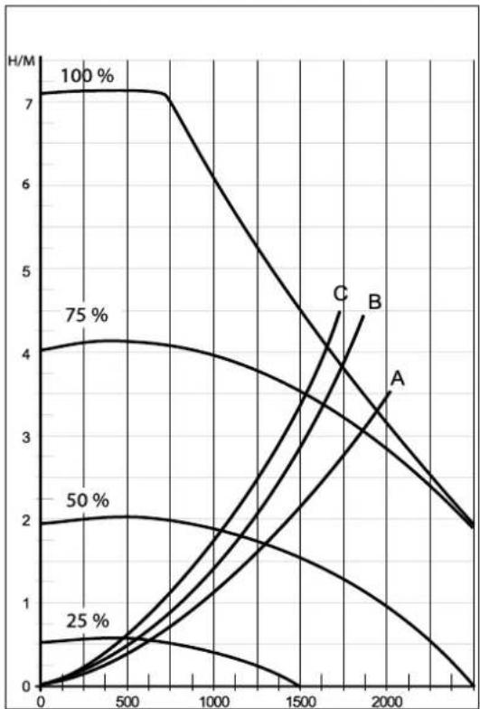
line
| x | A | B | C | 25% | 50% | 75% | | ---- | ---- | ---- | ---- | ---- | ---- | ---- | | 0 | 0.0 | 4.0 | 7.0 | 0.0 | 2.0 | 4.0 | | 500 | 0.5 | 3.5 | 6.5 | 0.5 | 2.0 | 4.0 | | 1000 | 1.0 | 3.0 | 5.0 | 1.0 | 1.5 | 3.5 | | 1500 | 1.5 | 2.5 | 3.5 | 1.5 | 1.0 | 3.0 | | 2000 | 2.0 | 2.0 | 2.0 | 2.0 | 0.5 | 2.0 | | 2500 | 2.5 | 1.5 | 1.0 | 2.5 | 0.0 | 1.5 |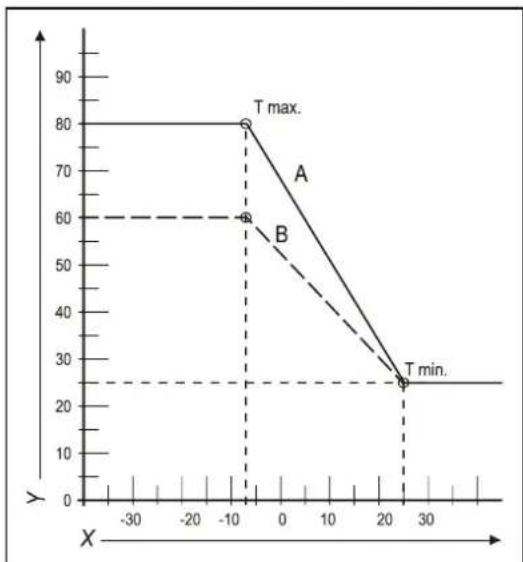
line
| X | Y | |---|---| | -10 | 60 | | -5 | 80 | | 25 | 25 | | 30 | 25 |B. Example
(Tmax CH = 60°C, Tmin CH = 25°C, Tmin ex = -7°C, Tmax ex = 25°C)
7.6 Conversion to different type of gas

CAUTION
Work on gas carrying parts may only be carried out by a certified installer.
If a unit is connected to a different type of gas than the one it has been set to by the manufacturer, the gas dosing ring must be replaced. Conversion sets for other types of gas are available to order.
Converting the dosing ring
- Switch off the boiler and remove the plug from the socket.
- Shut the gas valve.
- Remove the front panel from the unit.
- Loosen the coupling (A) above the gas block and turn the gas mixing tube (B) backwards.
- Replace the O-ring (C) and the gas dosing ring (D) by the rings in the conversion set.
- Reassemble it in reverse order.
- Open the gas valve.
- Check whether the gas couplings before the gas block are sealed.
- Enter the plug in the socket and switch on the boiler.
- Check whether the gas couplings after the gas block are sealed (during operation).
- Now check the setting of the gas/air ratio (see par. 7.7).
- Put a sticker of the configured gas type on top of the existing sticker at the gas block.
- Put a sticker of the configured gas type at the type plate.
- Return the front panel onto the unit.
7.7 Gas/air regulation
The gas/air regulation has been set at the factory and does not require any adjustments, in principle.
The setting can be checked by measuring the CO_2 percentage in the combustion gases or by measuring the offset.
In case of any disturbance, replacement of the gas block or conversion to a different type of gas, the regulation must be checked and set in accordance with the following tables.
| Gas type | Natural gas H | Propane P |
| Gas category | 2E/H G20 | 3P / G31 |
| CO2% at Low setting (L) (✗ and —)With open cover | See par.: 7.8 | See par.: 7.8 |
| CO2% at Low setting (H) (✗ and + 2x)With open cover | See par.: 7.8 | See par.: 7.8 |
| Initial gas pressure (mbar) | 20 mbar | 30/37/50 mbar |
| Gas dosing ring(only valid in combination with fan with integrated tunnel venturi (see drawing) | Natural gas H | Propane P |
| EKOMBG22ABV1 | 505 | 410 |
| EKOMBG28ABV1 | 600 | 480 |
| EKOMBG33ABV1 | 655 | 525 |

CAUTION
CO2 check must be carried out with open cover. If the cover is shut, the CO2% may be higher than the values stated in the above table.
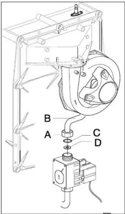
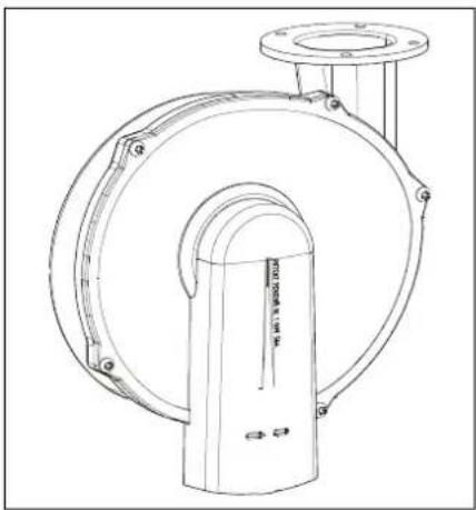
natural_image
Technical line drawing of a mechanical pump or valve assembly (no text or symbols)7.8 Setting gas/air regulation
The CO_2 setting has been set at the factory and does not require any adjustments, in principle. The setting can be checked by measuring the CO_2 percentage in the combustion gases. In case of any disturbance of the setting, the replacement of the gas valve or the conversion to a different type of gas must be checked, and if necessary set in accordance with the following instructions. Always check the CO_2 percentage when the lid is open.
Checking the carbon dioxide setting
1 Switch off the heat pump module with the user interface.
2 Switch off the gas boiler with the ① button. - appears on the service display.
3 Remove the front panel from the gas boiler.
4 Remove the sample point (a) and enter an appropriate chimney analysis probe.

IMPORTANT
Ensure the start-up procedure of the analysis machine has been completed before inserting the probe in the sample point.

IMPORTANT
Wait for the gas boiler to run stable. Faulty measurements may occur if the measuring probe is connected before the boiler is running stable.
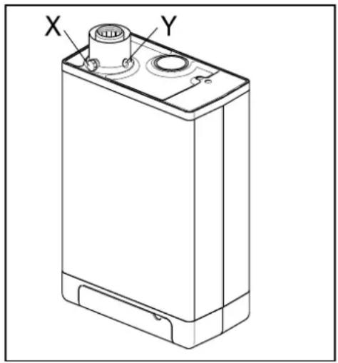
5 Switch on the gas boiler with the ① button and create a request for space heating.
6 Select the High setting by twice pressing the and + buttons simultaneously. A capital letter "H" will appear on the service display. The user display will show a Busy symbol. Do NOT carry out a test when a small letter "h" is shown. If this is the case, press and again.
7 Allow the display values to stabilize. Wait at least 3 minutes and compare the CO_2 percentage to the values in the following table.
| CO2value at maximum power | Natural gas G20 | Propane G31 (30/37/50 mbar) |
| Maximum value | 9.6 | 10.8 |
| Minimum value | 8.4 | 9.8 |
8 Note the CO _2 percentage at maximum power. This is important in relation to the following steps.

IMPORTANT
It is NOT possible to adjust the CO_2 percentage when the test program is being carried out. If the CO_2 percentage deviates from the values in the above table, contact your local service department.
9 Select the Low setting by once pressing the ✗ and — buttons simultaneously. "L" appears on the service display. The user display will show a Busy symbol.
10 Allow the display values to stabilize. Wait at least 3 minutes and compare the CO _2 percentage to the values in the following table.
| CO2 value at minimum power | Natural gas G20 | Propane G31 (30/37/50 mbar) |
| Maximum value | (a) | |
| Minimum value | 8.4 | 9.4 |
(a) CO _2 value at maximum power registered at setting High.
11 If the CO_2 percentage at maximum and minimum power is within the reach stated in the above tables, the CO_2 setting of the boiler is correct. If NOT, adjust the CO_2 setting in accordance with the instruction in the following chapter.
12 Switch off the unit by pressing the ① button and return the sample point to its position. Make sure it is gas tight.
13 Return the front panel to its place.

CAUTION
Work on gas carrying parts may ONLY be carried out by qualified, competent individuals.
Adjusting the carbon dioxide setting

IMPORTANT
Only adjust the CO_2 setting when you have first checked it and you have made sure the adjustment is necessary. No adjustments may be made to the gas valve without prior permission from your local Daikin distributor. In Belgium, the gas valve may NOT be adjusted and/or the seal may NOT be removed or broken. Contact your distributor.
1 Remove the cap (A) which covers the adjuster screw.
2 Turn the screw (B) to the right to increase the CO _2 percentage, and to the left to decrease it. See the following table for the desired value.
| Measured value at maximum power | Set values CO2(%) at minimum power (front lid open) | |
| Natural gas 2H (G20, 20 mbar) | Propane 3P (G31,30/50/37 mbar) | |
| 10.8 | - | 10.5±0.1 |
| 10.6 | 10.3±0.1 | |
| 10.4 | 10.1±0.1 | |
| 10.2 | 9.9±0.1 | |
| 10 | 9.8±0.1 | |
| 9.8 | 9.6±0.1 | |
| 9.6 | 9.0±0.1 | - |
| 9.4 | 8.9±0.1 | |
| 9.2 | 8.8±0.1 | |
| 9.0 | 8.7±0.1 | |
| 8.8 | 8.6±0.1 | |
| 8.6 | 8.5±0.1 | |
3 After measuring the CO 2 percentage and adjusting the setting, replace the cover cap and the sample point. Make sure they are gas tight.
4 Select the High setting by twice pressing the ✗ and buttons + simultaneously. A capital letter will appear on the service display.
5 Measure the CO 2 percentage. If the CO 2 percentage still deviates from the values in the table which indicates the CO 2 percentage at maximum power, contact your local distributor.
6 Press + and - simultaneously to leave the test program.
7 Return the front panel to its place.
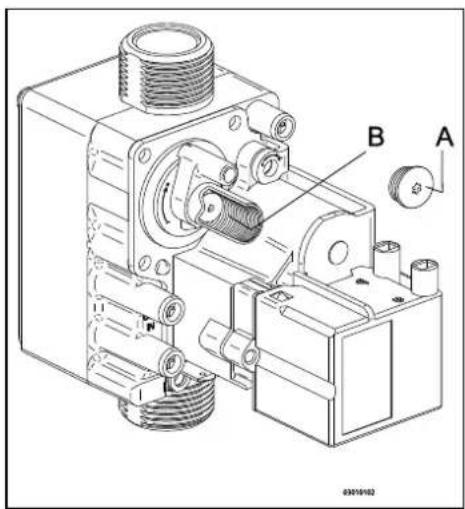
8 MALFUNCTIONS
8.1 Show last malfunction
Use the Ⓛ key to switch the unit off, and press the button.
The red malfunction LED is lit continuously, and the latest fault code is shown flashing on the temperature display.
If the unit has never detected a locking malfunction, no code will be displayed.
The last locking malfunction can be deleted by briefly pressing the ✿ button while pressing the — button.
8.2 Malfunction codes
If the malfunction LED is flashing, the boiler controller detects a fault. A malfunction code will be shown on the temperature display.
When the malfunction is rectified, the boiler controller can be restarted by pressing the reset ⏻ button.
The following faults can be distinguished:
| Temperature display | Description | Possible cause/solution |
| Unit is off. | ||
| 10, 11, 12, 13, 14 | Sensor fault S1 | Air in the installation. Purge the air from the boiler and CH installation.Check the connection of the ntc on the hot water tube.Check wiring for break.Replace S1. |
| 20, 21, 22, 23, 24 | Sensor fault S2 | Check wiring for break.Replace S2. |
| 0 | Sensor fault after self-check | Replace S1 and/or S2. |
| 1 | Temperature too high | Air in installation. Purge the air from the boiler and CH installation.Pump is not running. Reset or replace the pump, see par. 8.2.10 |
| 2 | Switch S1 and S2 | Check cable harness.Replace S1 or S2. |
| 4 | No flame signal | Main gas valve not opened.Gas supply pressure too low, or disappears.Condense output blocked.Check ignition unit and ignition cable.No or incorrect ignition distance, check this using the checking mold.Gas block or ignition unit is not receiving electrical current.Check earthing. |
| 5 | Poor flame signal | Condense output blocked.Gas supply pressure too low, or disappears.Check ignition unit and ignition cable.Check setting of gas block.Check earthing.Check air supply and gas output for possible recirculation of flue gases. |
| 6 | Flame detection error | Replace ignition cable + spark plug.Replace ignition unit.Replace boiler controller. |
| 8 | Fan rpm is not correct | Fan is coming up against cover insulation.Wiring between fan and cover.Check wiring or plug for lack of wire contact, measure 25-27V dc.Check and/or replace fan.Replace boiler controller. |
| 27 | Short circuit outdoor sensor | Check the wiring of the outdoor sensor.Replace outdoor sensor.Boiler controller is not suitable for this application.Replace boiler controller for the appropriate version. |
| 29, 30 | Gas valve controller fault | Replace boiler controller. |

Only replace faulty parts with the original Daikin parts.
Failing to fit or incorrectly fitting the sensors S1 and/or S2 may lead to serious damage.
8.3 Other faults
8.3.1 Boiler controller is noisy when igniting
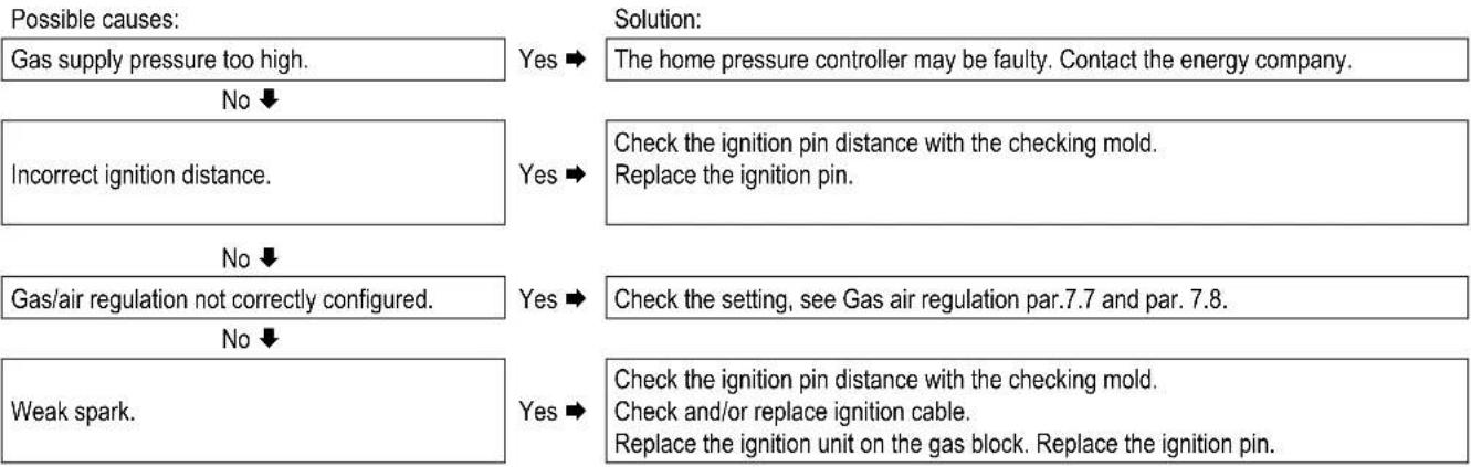
flowchart
graph TD
    A["Possible causes:"] --> B["Gas supply pressure too high."]
    B --> C{No}
    C -->|Yes| D["Solution: The home pressure controller may be faulty. Contact the energy company."]
    C -->|No| E["Incorrect ignition distance."]
    E --> F{Yes}
    F -->|Yes| G["Check the ignition pin distance with the checking mold. Replace the ignition pin."]
    F -->|No| H["Gas/air regulation not correctly configured."]
    H --> I{No}
    I -->|Yes| J["Solution: Check the setting, see Gas air regulation par.7.7 and par. 7.8."]
    I -->|No| K["Weak spark."]
    K --> L{Yes}
    L -->|Yes| M["Solution: Check the ignition pin distance with the checking mold. Check and/or replace ignition cable. Replace the ignition unit on the gas block. Replace the ignition pin."]
Checking mold ignition pin position
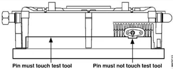
8.3.2 Boiler controller resonates
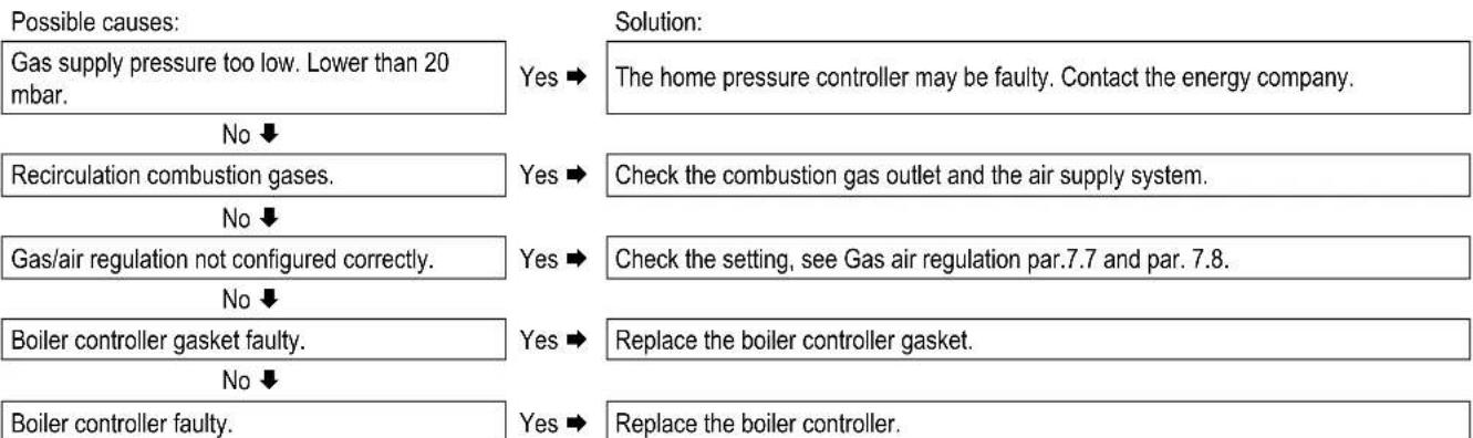
flowchart
graph TD
    A["Possible causes:"] --> B["Gas supply pressure too low. Lower than 20 mbar."]
    B --> C{No}
    C --> D["Recirculation combustion gases."]
    D --> E{No}
    E --> F["Gas/air regulation not configured correctly."]
    F --> G{No}
    G --> H["Boiler controller gasket faulty."]
    H --> I{No}
    I --> J["Boiler controller faulty."]

    K["Solution:"] --> L["Solution:"]
    L --> M["The home pressure controller may be faulty. Contact the energy company."]
    M --> N["Check the combustion gas outlet and the air supply system."]
    N --> O["Check the setting, see Gas air regulation par.7.7 and par. 7.8."]
    O --> P["Replace the boiler controller gasket."]
    P --> Q["Replace the boiler controller."]
8.3.3 No heating (CH)
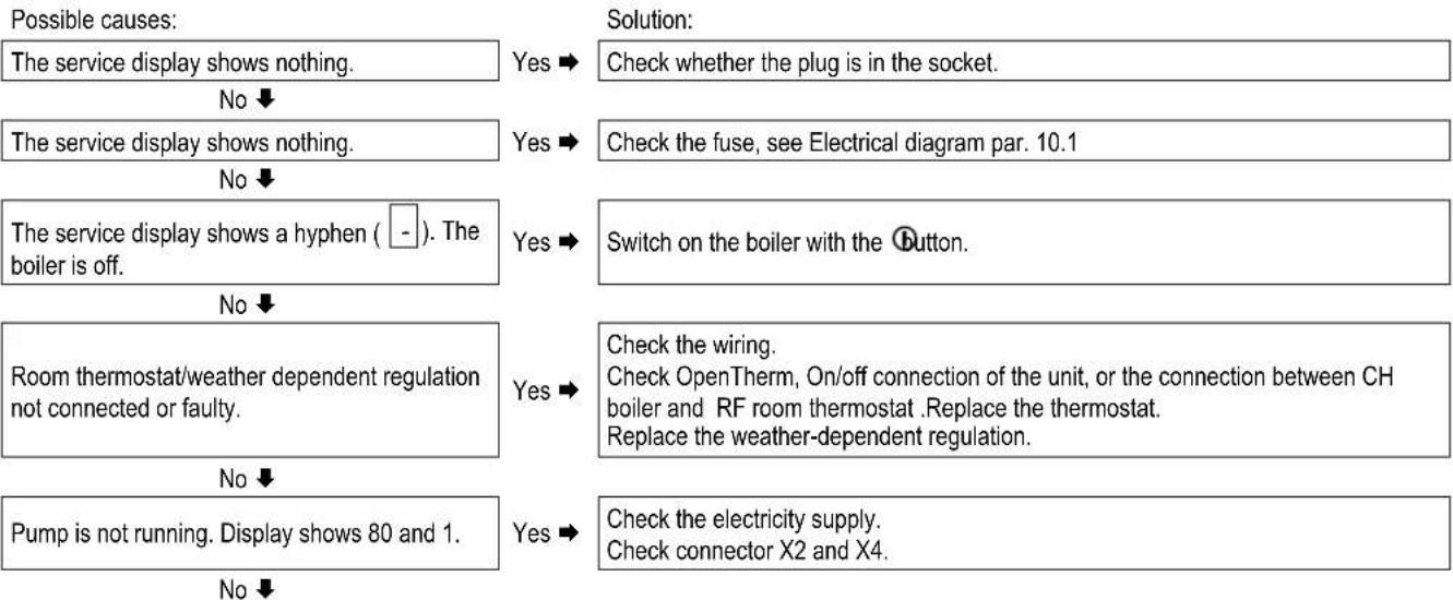
flowchart
graph TD
    A["Possible causes:"] --> B["The service display shows nothing."]
    B --> C{No}
    C -->|Yes| D["Check whether the plug is in the socket."]
    C -->|No| E["The service display shows nothing."]
    E --> F{No}
    F -->|Yes| G["Check the fuse, see Electrical diagram par. 10.1"]
    F -->|No| H["The service display shows a hyphen ( - ). The boiler is off."]
    H --> I{No}
    I -->|Yes| J["Switch on the boiler with the Button."]
    I -->|No| K["Room thermostat/weather dependent regulation not connected or faulty."]
    K --> L{No}
    L -->|Yes| M["Check the wiring. Check OpenTherm, On/off connection of the unit, or the connection between CH boiler and RF room thermostat .Replace the thermostat. Replace the weather-dependent regulation."]
    L -->|No| N["Pump is not running. Display shows 80 and 1."]
    N --> O{No}
    O -->|Yes| P["Check the electricity supply. Check connector X2 and X4."]
| No electrical supply (24 V). | Yes ➔ | Replace the faulty controller. Check the wiring in accordance with the diagram.Check the connector X4.Replace the faulty controller. |
8.3.4 The power is reduced
Possible causes:
At high rpm, the power has decreased.
Solution:
Yes →
Clean the unit and siphon.
Check the flue tube and the air supply system.
8.3.5 CH is not reaching correct temperature
Possible causes:
Water pressure in installation is too low.
No ↓
Room thermostat is not set correctly.
No ↓
Temperature is set too low.
No ↓
No flow through the installation.
No ↓
The boiler power is not set correctly.
No ↓
No heat transfer due to contamination in the CH boiler/installation.
Solution:
Yes →
Top up the installation. See par. 6.1.1.
Yes →
Check the setting and adjust if required.
Yes →
Increase the CH temperature See Operation CH. If there is an outdoor sensor: Check the outdoor sensor for short circuit: rectify this.
Yes →
Check the T ( ± 20^ C) between the supply and return CH. Ensure there is good flow through the installation.
Yes →
Adjust the boiler power. See Setting maximum CH power.
Yes →
Rinse the CH boiler/installation on the side of the CH.
8.3.6 No domestic hot water
Possible causes:
The service display shows nothing.
No ↓
The service display shows nothing.
No ↓
Flow sensor does not work.
No ↓
Tap flow < 1.5 l/min.
No ↓
No electricity supply on flow sensor (5V DC).
No ↓
S3 faulty.
No ↓
The thermostatic shower or bath tap is faulty.
Solution:
Yes →
Check whether the plug is in the socket.
Yes →
Check the fuse, see Electrical diagram par. 10.1
Yes →
Replace the flow sensor.
Yes →
Increase the tap flow.
Yes →
Check the wiring in accordance with the diagram.
Yes →
Replace S3.
Yes →
The thermostatic tap only lets through cold water. This means the tap flow through the boiler remains under 1.5l / min . Check the thermostatic tap.
8.3.7 DHW is not reaching the correct temperature
Possible causes:
Tap flow too high.
No ↓
DHW temperature set too low.
Solution:
Yes →
Reduce the tap flow. Check the dosing disk (EKOMBG22ABV1 and EKOMBG28ABV1)
Yes →
Increase the DHW temperature, see par. 7.1.
CH installation becomes hot during tapping.
No ↓
Insufficient heat transfer due to lime scale or contamination in the CH boiler on DHW side.
Yes →
Unwanted circulation in the ch circuit during hot water request due to thermosiphon effect or second pump in the CH circuit. Install a check valve in case of thermosiphon effect or a two-way valve in case of a second pump.
Yes →
Remove lime scale or rinse the CH boiler on the DHW side.
8.3.8 CH installation stays warm unwanted
Possible causes:
Room thermostat/weather dependent regulation faulty or short circuited.
Solution:
Yes →
Check the wiring.
Check OpenTherm, On/off connection of the unit, or the connection between CH boiler and RF room thermostat. Replace the thermostat.
Replace the weather-dependent regulation.
No ↓
CH installation is heated due to Tap comfort. The service display regularly shows code 7.
Yes →
Unwanted circulation in the CH circuit due to thermosiphon effect or second pump in the CH circuit. Install a check valve in case of thermosiphon effect or a two-way valve in case of a second pump.
8.3.9 A-label pump LED flashes intermittently red/green
Possible causes:
Too high or too low mains voltage.
Solution:
Yes →
Check the mains voltage.
No ↓
Pump temperature is too high.
Yes →
Check the water and ambient temperature.
8.3.10 A-label pump LED flashes red
Possible causes:
Pump stopped.
Solution:
Yes →
Reset the pump by switching off the unit by pressing the on/off button for at least 20 seconds (attention: if the pump has been set to continuous, the pump can only be reset by pulling the plug from the socket).
Replace the pump.
9 MAINTENANCE
The unit and the installation must be checked by a certified installer, and cleaned if necessary.

CAUTION
Work on gas carrying parts may only be carried out by a certified installer.
After work, check the flue gas carrying parts for air tightness. If the unit has just been operational, some parts may be hot.
9.1.1 Disassembly
- Switch the unit off with the ① button.
- Remove the plug from the socket.
- Shut the gas valve.
- Open the display valve and loosen the two screws on the left and right of the display, and remove the front panel.
- Wait until the unit has cooled down.
- Unscrew the coupling nut at the bottom of the flue tube to the left.
- Slide the flue gas pipe upwards (1) with a turn to the left until the bottom of the pipe reaches above the coupling of the condense outlet container. Pull the bottom of the pipe forward (2) and remove the pipe by rotating it to the left and down (3).
- Lift the condense outlet tray from the connection of the siphon (4) on the left, and turn it to the right with the siphon connection over the edge of the bottom tray (5). Push down the condense outlet tray at the back from the connection to the heat exchanger (6) and remove it from the unit.
- Take the connector from the fan and the ignition unit from the gas block.
- Disconnect the coupling under the gas block.
- Unscrew the shouldered bolts (hex key) of the front lid and remove it to the front, complete with gas block and fan (be careful not to damage the boiler controller, insulation plate, gas block, gas pipe and fan). Lay the removed front lid with the foot rests horizontally on a flat surface.
- The boiler controller and the integrated insulation plate do not require any maintenance (do not need cleaning). Therefore never use a brush or compressed air to clean these parts, in order to avoid dust developing.
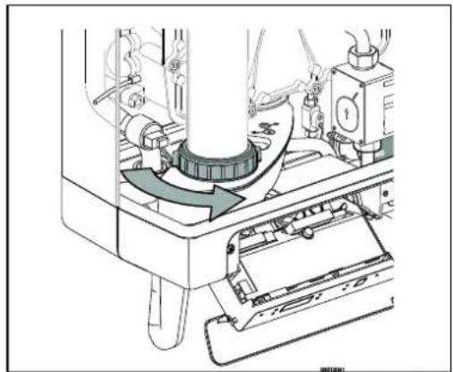
natural_image
Mechanical assembly diagram showing a rotating component with arrows indicating motion (no text or symbols)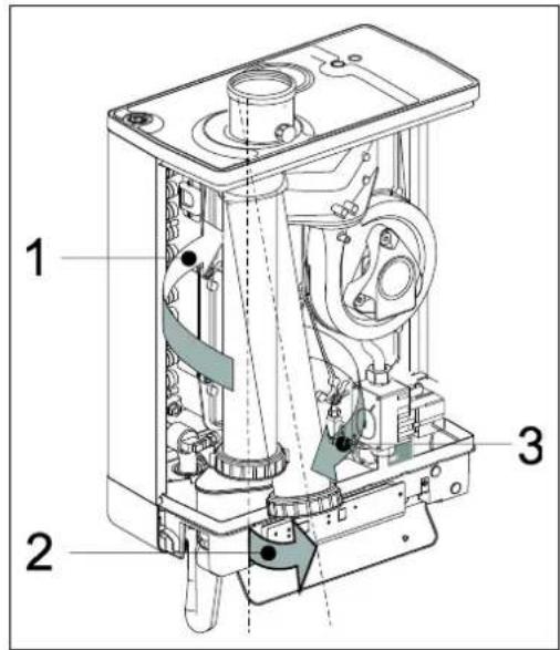
9.1.2 Cleaning
- Clean the heat exchanger with a brush or vacuum cleaner, from top to bottom.
- Clean the bottom of the heat exchanger.
- Clean the condense outlet tray with water.
- Clean the siphon with water.
- Clean the inside and bottom of the front plate with a soft brush.

CAUTION
The integrated insulation plate and boiler controller gasket contain ceramic fibers.
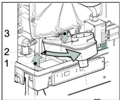
9.1.3 Fitting

During maintenance the front plate seal needs to be replaced. When assembling, check the other seals for damages, hardening, (hairline) fractures and/or discoloration. Where necessary, place a new seal. Also check the correct positioning.
-
Check that between the flange of the shoulder bolt and the front plate, there is a thin layer of ceramic grease. If there is no or insufficient grease, it must be applied (see image).
-
Note: Replace the seal around the front cover. Clean the seal ring chamber with a soft brush and make sure the new o-ring is pressed in well all around. Avoid stretching or tearing. Place the front lid on the heat exchanger and secure it with the special shoulder bolts (hex key). Make sure that the o-ring remains in place when installing the front plate. Evenly tighten the shoulder bolts crosswise manually (10 - 12 Nm). For the sequence of tightening, see image.
-
Evenly manually tighten the boiler controller bolts crosswise.
-
Fit the gas coupling under the gas block.
-
Fit the connector onto the fan and the ignition unit onto the gas block.
-
Fit the condense outlet tray by sliding it into the outlet stump of the switcher (1), with the siphon connection, before the bottom tray. Then turn the condense outlet tray to the left (2) and push it down into the siphon connection (3). Make sure that the rear of the condense outlet tray ends up resting on the cam at the back of the bottom container (A).
-
Fill the siphon with water and fit it onto the connection under the condense outlet tray.
-
Slide the flue gas pipe, while turning it to the left, with its top around the flue gas adapter in the top lid. Insert the bottom into the condense outlet tray, drag the gasket down and tighten the swivel head to the right.
-
Open the gas valve and check the gas couplings under the gas block and on the assembly bracket for leakage.
-
Check the CH and the water pipes for leakage.
-
Insert the plug into the socket.
-
Switch the unit on with the Ⓐ button.
-
Check the front lid, the connection of the fan to the front lid and the flue tube parts for leaks.
-
Check the gas-air regulation (see par. 7.7 and par. 7.8) and check the gas coupling on the gas block for gas tightness.
-
Assemble the cover and tighten the two screws to the left and the right of the display, and close the display cover.
-
Check the heating and the hot water provision for correct functioning.
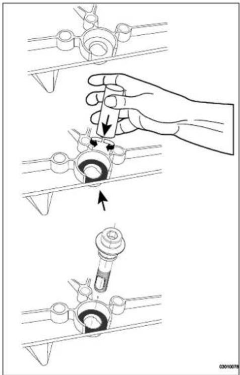

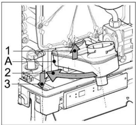
9 TECHNICAL SPECIFICATIONS
| Model name | EKOMBG22ABV1 | EKOMBG28ABV1 | EKOMBG33ABV1 |
| Condensing boiler | Yes | Yes | Yes |
| Low temperature boiler | No | No | No |
| B1 boiler | No | No | No |
| Combination heater | Yes | Yes | Yes |
| Domestic water | ||||
| Nom. load upper value, Qn (Hs) | kW | 6.1 – 25.9 | 7,9 – 32,3 | 8,4 – 36,3 |
| Nom. load lower value, Qn (Hi) | kW | 5.5 – 23.3 | 7.1 – 29.1 | 7.6 – 32.7 |
| Domestic water threshold | l/min | 2 | ||
| Domestic water quantity 60°C | l/min | 6 | 7.5 | 9 |
| Domestic water quantity 40°C (mixed) | l/min | 10 | 12.5 | 15 |
| Domestic water temperature | °C | 60 | ||
| Domestic water side pressure difference | kPa | See par. 5.2 | ||
| CH | ||||
| Nom. load upper value, Qn (Hs) | kW | 6.1 – 25.9 | 7,9 – 32,3 | 8,4 – 36,3 |
| Nom. load lower value, Qn (Hi) | kW | 5.5 – 23.3 | 7.1 – 29.1 | 7.6 – 32.7 |
| Nom. output Pn | kW | 6,0 - 22,6 | 7,6 - 28,2 | 8,3 - 32,0 |
| Max. CH water pressure PMS | bar | 3 | ||
| Max. CH water temperature | °C | 90 | ||
| Other data | ||||
| Gas consumption G25 (1) | m3/h | 0.62 – 2.82 | 0.84 – 3.46 | 0.89 – 3.92 |
| Gas consumption G20 (1) | m3/h | 0.58 – 2.42 | 0.74 – 3.02 | 0.79 – 3.39 |
| Gas consumption G31 (1) | m3/h | 0.21 – 0.94 | 0.29 – 1.19 | 0.30 – 1.29 |
| Pressure loss of the unit (CH) | mH2O | See par. 7.4 | ||
| Max. Flue gas temperature DHW | °C | 70 | 70 | 70 |
| Mass.flow flue gas (max) | g/s | 10,8 | 13,5 | 15,1 |
| Available fan pressure | Pa | 75 | 75 | 75 |
| NOx class | 6 | 6 | 6 | |
| NOx | mg/kWh | 28 | 27 | 36 |
| P1, at 30% of Rated input (30/37) | kW | 7,5 | 9,4 | 10,7 |
| P4, Rated output (80/60) | kW | 22,6 | 28,2 | 32,0 |
| η 1, Efficiency at P1 | % | 96.4 | 96.8 | 98,2 |
| η 4, Efficiency at P4 | % | 87,1 | 87,2 | 88,0 |
| Standby heat loss, Pstby | kW | 0.037 | 0,037 | 0,038 |
| Daily fuel consumption, Qfuel | kWh | 14,463 | 22.884 | 22,573 |
| Daily electricity consumption, Qelec | kWh | 0,064 | 0,076 | 0,071 |
| Electrical data | ||||
| Mains voltage | V | 230 | ||
| Safety class | IP | IPX4D, (B23, B33 = IP20) | ||
| Absorbed power: full load | W | 80 | ||
| Absorbed power: standby | W | 2 | ||
| Auxiliary electricity consumption at full load (elmax) | kW | 0,045 | 0,045 | 0,045 |
| Auxiliary electricity consumption at part load (elmin) | kW | 0,015 | 0,015 | 0,015 |
| Auxiliary electricity consumption in stand by mode (Psb) | kW | 0,002 | 0,002 | 0,002 |
| Installation measurements and weight | ||||
| Height | mm | 590 | 650 | 710 |
| Width | mm | 450 | ||
| Depth | mm | 240 | ||
| Weight | kg | 30 | 33 | 36 |
Gas category (1) (EN 15502)
B23; B33; C13x; C33x; C43x; C53x; C63x; C83x: C93x
| Destination country | Boiler categorie (EN437) | Gas type and gas inlet pressure (EN 437) | |
| IT | II2H3P | G20, 20 mbar, G31: 37 mbar | |
| FR | II2Esi3P | G20, 20 mbar, G25: 25 mbar, G31: 37 mbar | |
| BE | I2E(S) | G20, 20 mbar, G25: 25 mbar | |
| PL | II2E3P | G20, 20 mbar, G31: 37 mbar | |
| DE | II2ELL3P | G20, 20 mbar, G25: 20 mbar, G31: 50 mbar | |
| GR | II2H3P | G20, 20 mbar, G31: 37 mbar | |
| PT | II2H3P | G20, 20 mbar, G31: 37 mbar | |
(1) G20 – Natural gas E/H
G25 - Natural gas LL/L
G31 – Liquefied Propane gas
9.1 Technical Product Fiche in accordance to CELEX-32013R0811
| Supplier | Daikin Europe NVZandvoordestraat 3008400 OostendeBelgium | ||||
| Type designation | EKOMBG22ABV1 | EKOMBG28ABV1 | EKOMBG33ABV1 | ||
| Seasonal space heating energy efficiency class | - | - | A | A | A |
| Heat rated output | P_rated | kW | 23 | 28 | 32 |
| Annual energy consumption | Q_HE | GJ | 44 | 55 | 61 |
| Seasonal space heating energy efficiency | _s | % | 91 | 92 | 93 |
| Sound power level | L_WA | dB | 50 | 50 | 50 |
| Declared load profile | - | - | L | XL | XL |
| Water heating energy efficiency class | - | - | A | A | A |
| Annual electricity consumption | AEC | kWh | 14 | 17 | 16 |
| Annual fuel consumption | AFC | GJ | 11 | 18 | 18 |
| Water heating energy efficiency | _WH | % | 80 | 83 | 84 |
| Efficiency class controller | II | II | II | ||
| Contribution to yearly efficiency | % | 2,0 | 2,0 | 2,0 | |
| IMPORTANTPlease read all instructions before fitting this appliance.This appliance is not intended for use of persons (including children) with diminished physical, sensory or mental ability, or lack of experience and knowledge, unless supervised by, or instruction about the use of the appliance by a person who is responsible for their safety.The appliance and installation should every year be inspected by an qualified installer and cleaned when necessary.The appliance can be cleaned with a damp cloth. Don't use aggressive or abrasive cleaning- or solvent | |||||
9.2 Electrical diagram
| A | Earth connection heat exchanger | F | Fuse (3.15 AT) | P1 | CH pump | S5 | Flow sensor |
| B | Spark cover | G | Gas valve + ignition unit | S1 | Supply sensor | S7 | CH water pressure sensor |
| C | Boiler controller | I | Ignition/ionization pin | S2 | Return sensor | V | Fan |
| E | Earth lips boiler controller | M | Mains voltage | S3 | DHW sensor |
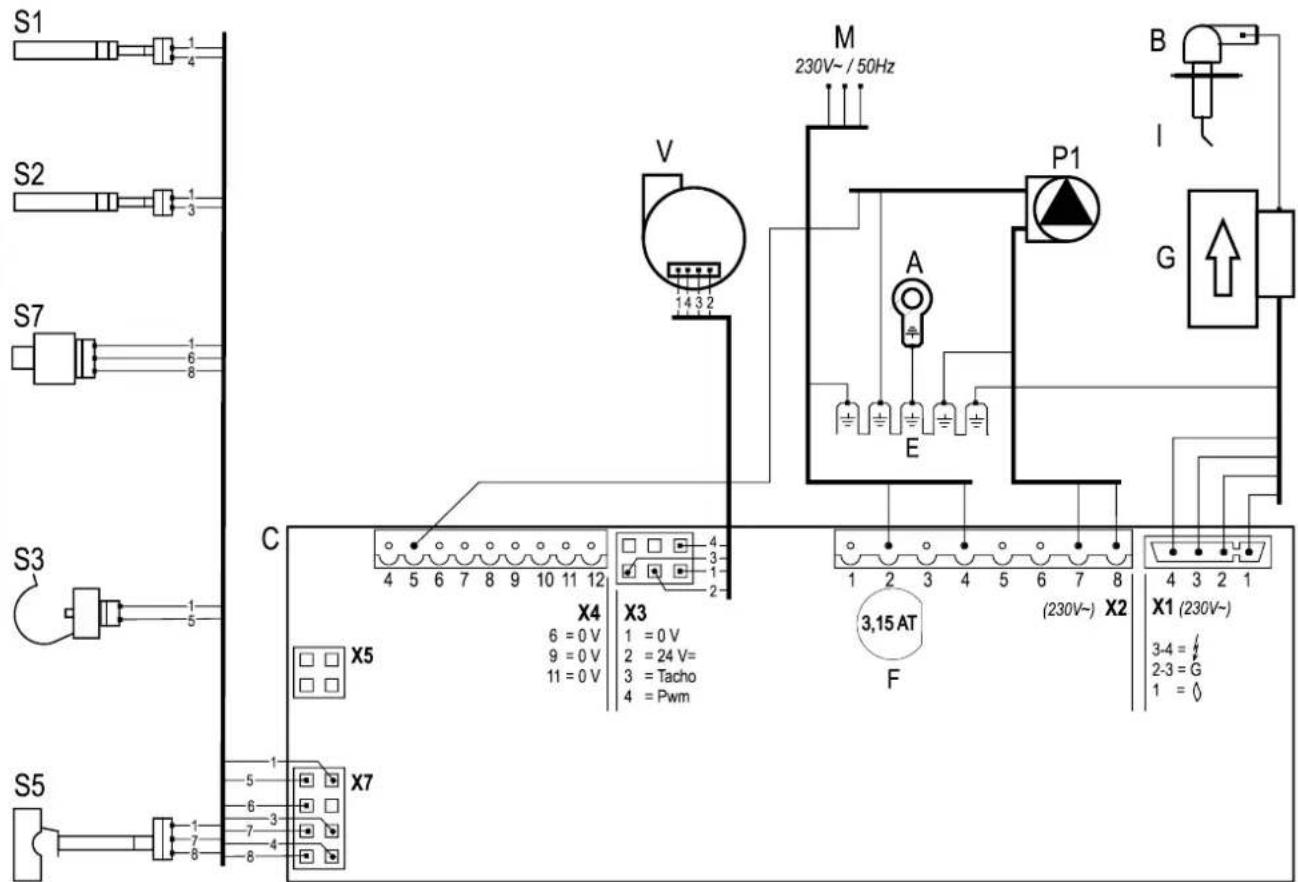
| Connecting: | |||
| Connector X424V= | 5 - ± | [X486] | CH pump (5= PWM signal (red), E=earth) |
| 6 - 7 | [X22D] | On/off room thermostat and/or frost thermostat (24Vdc or ± 125mA) | |
| 8 - 9 |  | Outdoor sensor (12 k Ohm / 25°C) | |
| 9 - 10 | [0236] | Tank sensor or tank thermostat (if through connection 9 – 10 present, then remove it) | |
| 11 - 12 | [6A50] | OpenTherm thermostat | |
| Connector X2230V~ | 2 - 4 |  | Mains cable (2=L (brown), 4=N (blue), E=earth) |
| 7 - 8 |  | CH-pump (8=L (brown), 7=N (blue), E=earth) | |
| 3 – 5 - 6 | [A8ZS] | Floor heating or group regulation valve. (3=L (brown), 5=switch (black), 6=N (blue)) (EK3WV1AA). | |
| 3 – 5 - 6 |  | Three-way valve (3=L (brown), 5=switch (black), 6=N (blue)) (EK3WV1AA). | |
| Connector X5 |  | Computer interface | |
9.3 NTC resistances
| NTC 12k Ohm | |||||
| T [°C] | R [ohm] | T [°C] | R [ohm] | T [°C] | R [ohm] |
| -15 | 76020 | 25 | 12000 | 65 | 2752 |
| -10 | 58880 | 30 | 9805 | 70 | 2337 |
| -5 | 45950 | 35 | 8055 | 75 | 1994 |
| 0 | 36130 | 40 | 6653 | 80 | 1707 |
| 5 | 28600 | 45 | 5522 | 85 | 1467 |
| 10 | 22800 | 50 | 4609 | 90 | 1266 |
| 15 | 18300 | 55 | 3863 | 95 | 1096 |
| 20 | 14770 | 60 | 3253 | 100 | 952 |
10 WARRANTY CONDITIONS
The general warranty conditions of Daikin Europe NV apply to this product.
The warranty is void if it is determined that the faults, damages, or undue wear are attributable to improper use or inexpert treatment or inexpert repair, setting, installation or maintenance, by non-certified installers, or that it was exposed to substances with aggressive chemicals (incl. hair spray) and other damaging substances.
The warranty also becomes void when pipes and couplings have been applied in the installation which may cause oxygen diffusion, or the defect is a consequence of lime scale (damaging to the unit and installation). Surface damage as well as transport damage is included under the warranty. The entitlement to warranty becomes void if it cannot be proven that the CH boiler has been subjected to maintenance by a certified installer at least once a year from the commissioning date. The instructions for installation and use which we provide for units must be followed in full.
Environment

If the unit is due for replacement, it can usually be taken back by your dealer, following consultation. Should this not be possible, consult your council for the possibilities for recycling or environmentally friendly processing of used materials.
Various plastics and metals were used in the manufacturing of the unit. Furthermore, the unit contains electrical components which belong with electronic waste.
Use as intended
The unit, as described in this documentation is intended for heating spaces via a central heating installation and/or the supply of hot water. Any other usage falls outside the intended use of the unit. No liability can be accepted on damage arising from incorrect use.
INHALTSVERZEICHNIS
© 2022 Daikin Europe NV
natural_image
Line drawing of a rectangular electronic device with a cylindrical top and side ports (no text or symbols)A. ZH-Pumpe
B. Gasventil
4.2 Installationsort
natural_image
Technical line drawing of a mechanical assembly with labeled component A (no text or symbols beyond label)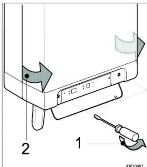
4.3 Montage
natural_image
Technical line drawings of mechanical components with screws and bolts (no text or symbols)natural_image
Technical line drawing of a mechanical device with internal tubing and component cluster (no text or symbols)
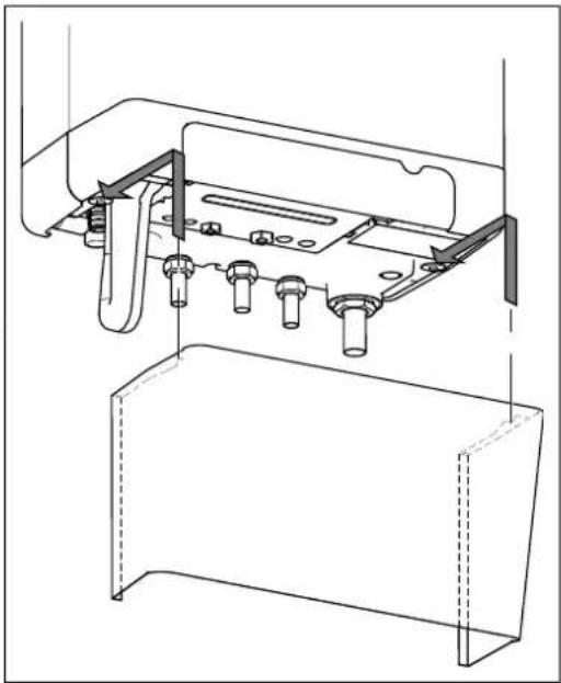
natural_image
Technical line drawing of a mechanical assembly with no visible text or symbols5 ANSCHLIEßEN
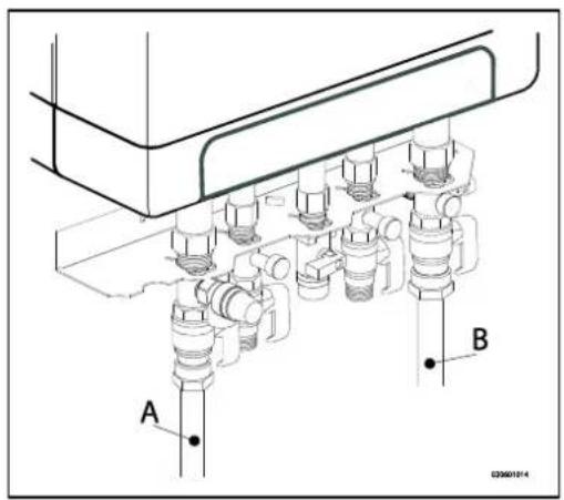
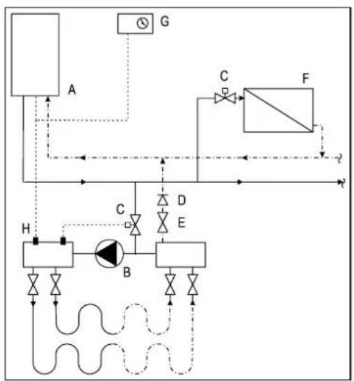
flowchart
graph TD
    A["Component A"] -->|Flow| B["Component B"]
    B -->|Control| C["Component C"]
    C -->|Flow| D["Component D"]
    D -->|Control| E["Component E"]
    E -->|Flow| F["Component F"]
    F -->|Control| G["Component G"]
    G -->|Flow| H["Component H"]
    H -->|Control| A
    style A fill:#f9f,stroke:#333
    style B fill:#ccf,stroke:#333
    style C fill:#cfc,stroke:#333
    style D fill:#fcc,stroke:#333
    style E fill:#cff,stroke:#333
    style F fill:#ffc,stroke:#333
    style G fill:#fff,stroke:#333
    style H fill:#fcf,stroke:#333
natural_image
Technical line drawing of a mechanical assembly with labeled component A (no text or symbols present)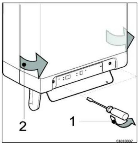
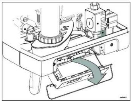
natural_image
Technical diagram of a mechanical assembly with no visible text or symbols5.3.1 Elektroanschlüsse
5.4.3 Modulierendes Funk-Raumthermostat

natural_image
Technical diagram of a pipe system with airflow indicators and structural components (no text or symbols)6 INBETRIEBNAHME DES GERÄTS UND DER INSTALLATION
natural_image
Technical line drawing of a mechanical component with labeled point A (no text or symbols beyond label)natural_image
Technical line drawing of a mechanical assembly with threaded component and labeled part D (no text or symbols beyond labels)$$ (T \max Z H = 6 0 ^ {\circ} C, T \min Z H = 2 5 ^ {\circ} C, T \min a u \beta e n = - 7 ^ {\circ} C, $$
$$ \text { Tmax außen } = 2 5 ^ {\circ} \mathrm{C}) $$
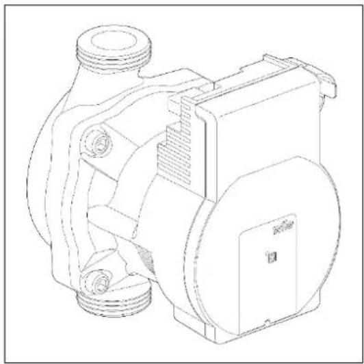
natural_image
Technical line drawing of a mechanical pump or motor assembly (no text or symbols)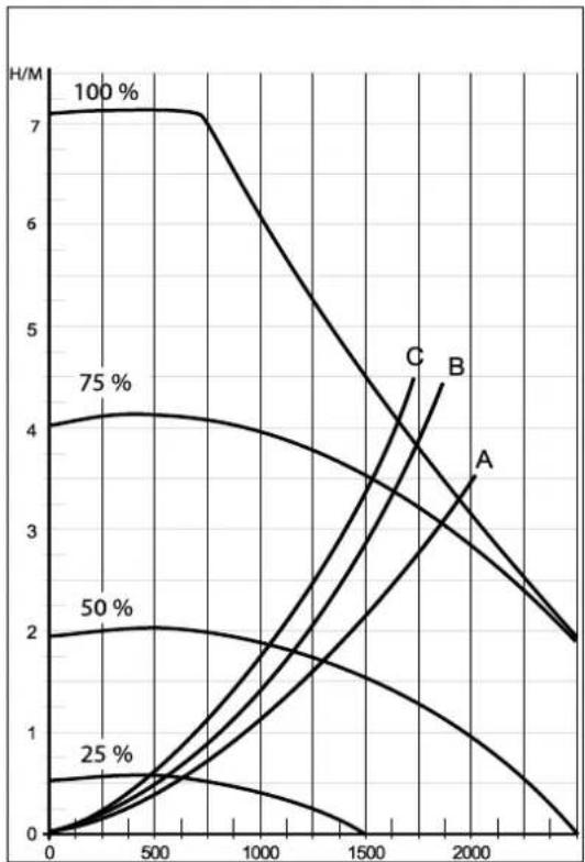
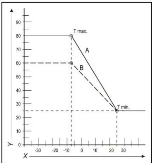
line
| X | A | B | | ---- | --- | --- | | -10 | 80 | 60 | | 25 | 25 | 25 |8 STÖRUNGEN
natural_image
Mechanical assembly diagram showing a rotating component with directional arrows indicating motion (no text or symbols)
9.1.2 Reinigen
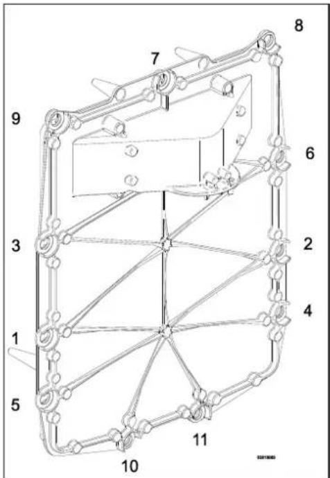
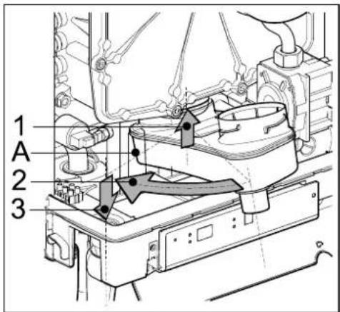
10 TECHNISCHE DATEN
© 2022 Daikin Europe NV
natural_image
Line drawing of a rectangular electronic device with mounting holes and a central cylindrical component (no text or symbols)A. Pompe CH
B. Vanne de gaz
N. Bloc raccord/barrette de raccordement X4
O. Bac de purge de condensat
natural_image
Technical line drawing of a mechanical assembly with labeled component A (no text or symbols beyond label)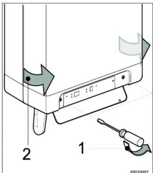
4.3 Assemblage
natural_image
Technical line drawings of mechanical components with screws and bolts (no text or symbols)natural_image
Technical line drawing of a mechanical device with internal components and housing (no text or symbols)
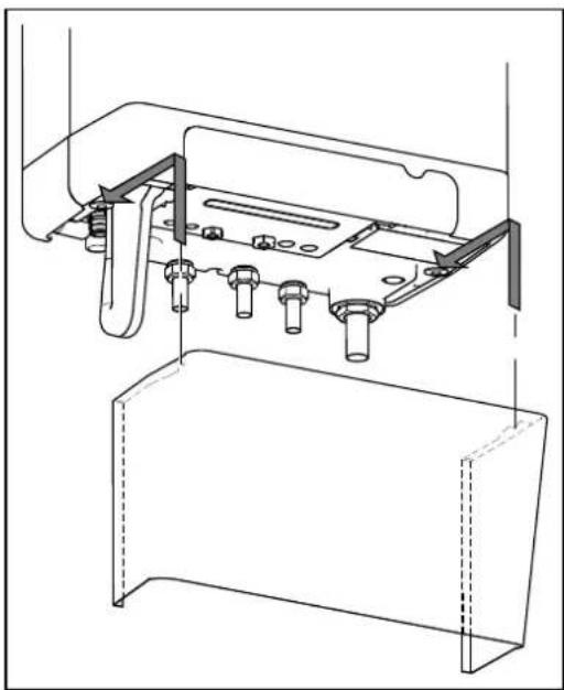
natural_image
Technical line drawing of a mechanical assembly with mounting brackets and bolts (no text or symbols)5 CONNEXION
natural_image
Technical line drawing of a mechanical assembly with labeled component A (no text or symbols present)

natural_image
Technical diagram of a mechanical assembly with no visible text or symbols5.4.3 Thermostat d'ambiance modulant, sans fil

natural_image
Technical diagram of a pipe system with airflow indicators and structural components (no text or symbols)6 MISE EN SERVICE DE L'UNITE ET DE L'INSTALLATION
natural_image
Technical line drawing of a mechanical assembly with threaded ports and internal components (no text or symbols)natural_image
Technical line drawing of a mechanical pump or motor assembly (no text or symbols)
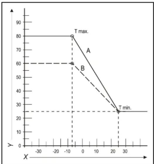
line
| X | Y | | ---- | ---- | | -10 | 80 | | -10 | 60 | | 20 | 25 |natural_image
Technical line drawing of a rectangular battery casing with labeled ports X and Y (no text or symbols beyond labels)8 DYSFONCTIONNEMENTS
natural_image
Mechanical assembly diagram showing a rotating component with directional arrows indicating motion (no text or symbols)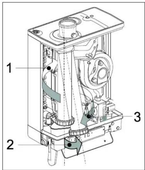
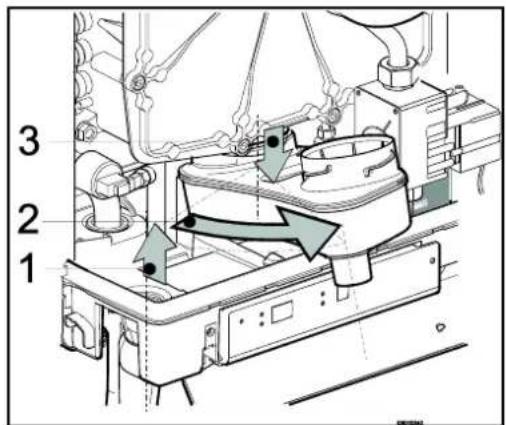
9.1.3 Montage


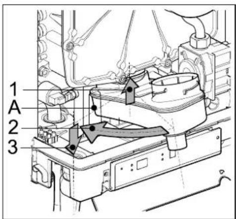
© 2022 Daikin Europe NV
natural_image
Line drawing of a rectangular electronic device with a cylindrical top and mounting base (no text or symbols)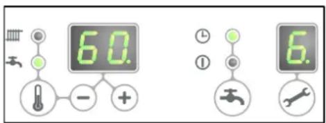
Zelftest
A. A-label CV-pomp
B. Gasblok
P. Warmwatersensor S3
Q. Sifon
R. Warmtewisselaar
• DN15
• Drukklasse (MOP)5
• High temperature class C

CAUTION
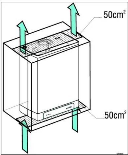
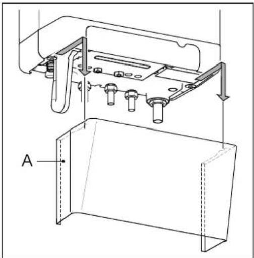
natural_image
Technical line drawing of a mechanical assembly with labeled component A (no text or symbols beyond label)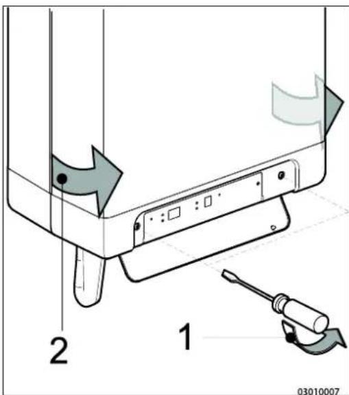
4.3 Montage
natural_image
Technical line drawings of mechanical components with bolts and connectors (no text or symbols)natural_image
Technical line drawing of an electrical enclosure with internal wiring and a multi-tiered base unit (no text or symbols)4.3.3 Toestel monteren
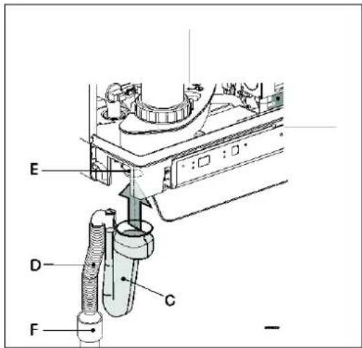
natural_image
Technical line drawing of a mechanical assembly with no visible text or symbols5 AANSLUITEN

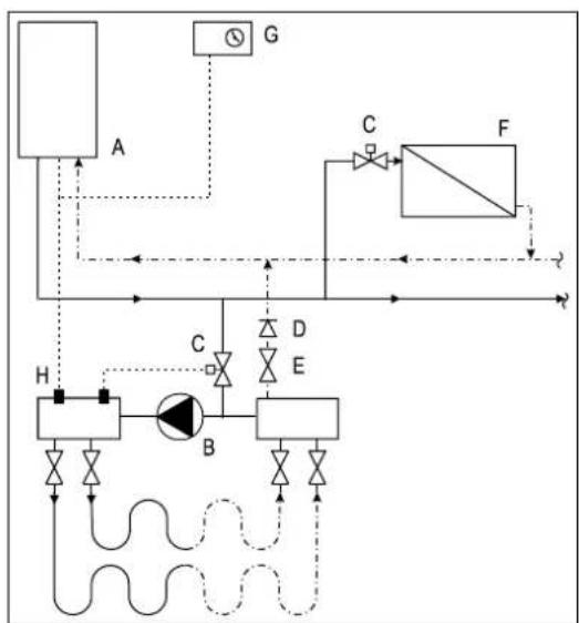
flowchart
graph TD
    A["A"] --> G["G"]
    G --> C["C"]
    C --> F["F"]
    F --> H["H"]
    H --> B["B"]
    B --> D["D"]
    D --> E["E"]
    E --> B
    B --> F
    style A fill:#f9f,stroke:#333
    style B fill:#ccf,stroke:#333
    style C fill:#cfc,stroke:#333
    style D fill:#fcc,stroke:#333
    style E fill:#cff,stroke:#333
    style F fill:#ffc,stroke:#333
    style G fill:#fff,stroke:#333
    style H fill:#fff,stroke:#333
    style_I[" "] --> A
    I --> B
    I --> C
    I --> D
    I --> E
line
| X | A | B | C | | ---- | --- | --- | --- | | 0.0 | 1.0 | 1.0 | 1.0 | | 0.2 | 3.0 | 3.5 | 4.0 | | 0.4 | 5.0 | 6.0 | 7.0 | | 0.6 | 6.5 | 8.0 | 9.0 | | 0.8 | 8.0 | 10.0 | 11.0 | | 1.0 | 9.5 | 11.5 | 12.5 | | 1.2 | 10.5 | 12.5 | 13.5 | | 1.4 | 11.5 | 13.5 | 14.5 | | 1.6 | 12.5 | 14.5 | 15.5 | | 1.8 | 13.5 | 15.5 | 16.5 | | 2.0 | 14.5 | 16.5 | 17.5 |natural_image
Technical line drawing of a mechanical assembly with labeled component A (no text or symbols beyond label)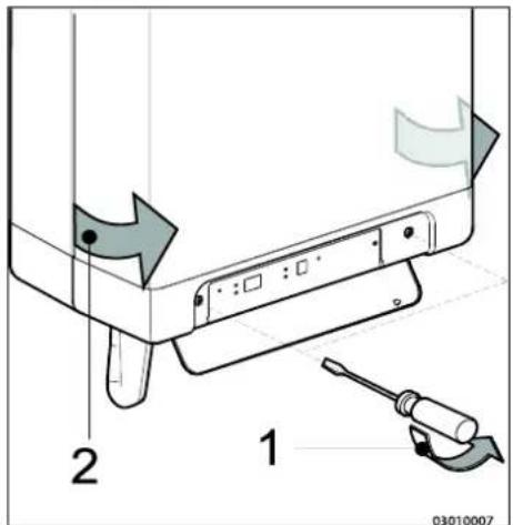

natural_image
Technical diagram of a mechanical assembly with no visible text or symbols5.4.3 Modulerende kamerthermostaat, draadloos

natural_image
Technical diagram of a mechanical assembly with multiple cylindrical components and labeled point E (no text or symbols beyond label)RGA = Rookgasafvoer, LTV = Luchttoevoer
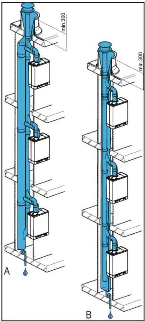
natural_image
Technical diagram of a pipe system with a blue-tinted duct and brick wall, showing airflow direction (no text or labels)6 IN BEDRIJF STELLEN VAN HET TOESTEL EN DE INSTALLATIE
natural_image
Technical line drawing of a mechanical component with labeled section A (no text or symbols beyond label)natural_image
Technical line drawing of a mechanical device with threaded shaft and internal components (no text or symbols)$$ (T \max C V = 8 0 ^ {\circ} C, T \min C V = 2 5 ^ {\circ} C, T \min b u = - 7 ^ {\circ} C, T \max b u = 2 5 ^ {\circ} C) $$
B. Voorbeeld
$$ (T \max C V = 6 0 ^ {\circ} C, T \min C V = 2 5 ^ {\circ} C, T \min b u = - 7 ^ {\circ} C, T \max b u = 2 5 ^ {\circ} C) $$
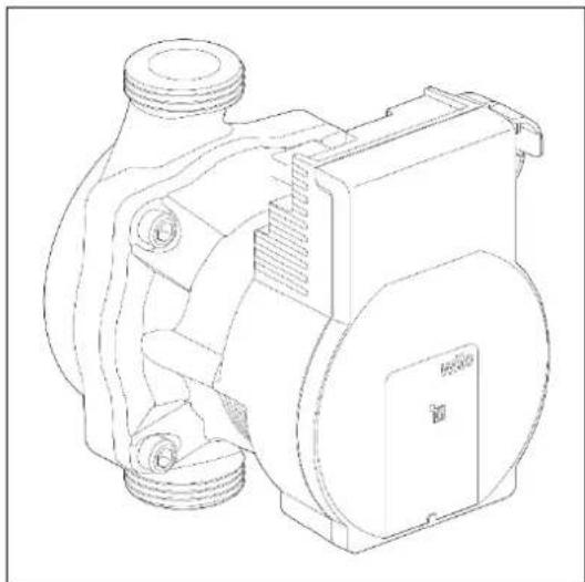
natural_image
Technical line drawing of a mechanical pump or motor assembly (no text or symbols)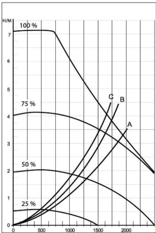
line
| x | 100 % | 75 % | 50 % | 25 % | A | | ---- | ----- | ---- | ---- | ---- | ----- | | 0 | 7.0 | 4.0 | 2.0 | 0.5 | 0.0 | | 500 | 7.0 | 4.1 | 2.1 | 0.6 | 0.1 | | 1000 | 6.5 | 3.8 | 1.8 | 0.4 | 0.3 | | 1500 | 5.0 | 3.5 | 1.5 | 0.2 | 0.6 | | 2000 | 3.5 | 2.5 | 1.0 | 0.1 | 1.0 | | 2500 | 2.0 | 1.5 | 0.5 | 0.0 | 1.5 |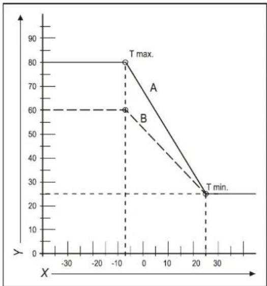
line
| X | Y | | ---- | ---- | | -10 | 80 | | -10 | 60 | | 20 | 25 |natural_image
Technical line drawing of a rectangular battery casing with labeled ports X and Y (no text or symbols beyond labels)8 STORINGEN
Branderpakking defect.
Nee ↓
Brander defect.
Oplossing:
Ja →
natural_image
Mechanical assembly diagram showing a rotating component with directional arrows indicating motion (no text or symbols)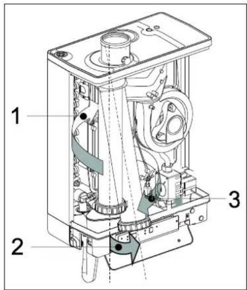
9.1.2 Reinigen
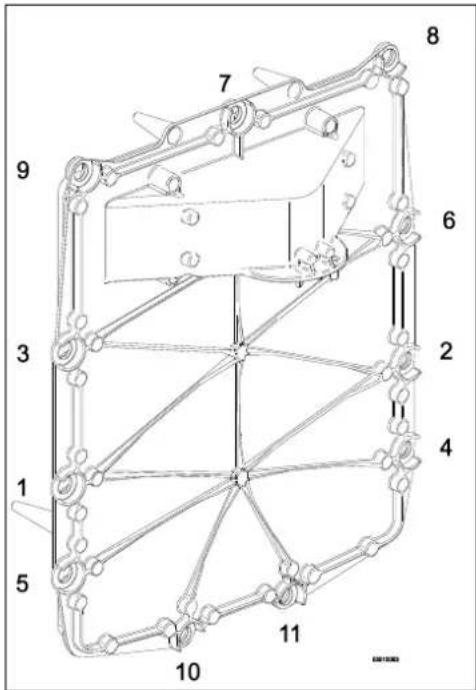

10 TECHNISCHE SPECIFICATIES
10.1 Technical Product Fiche in accordance to CELEX-32013R0811
© 2022 Daikin Europe NV
natural_image
Line drawing of a rectangular electronic device with a cylindrical top and mounting base (no text or symbols)A. Pompa CH
B. Valvola del gas
natural_image
Technical line drawing of a mechanical assembly with labeled component A (no text or symbols beyond label)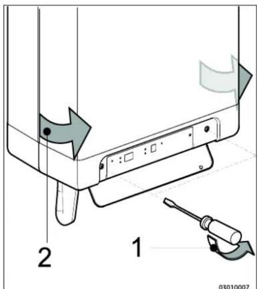
4.3 Montaggio
natural_image
Technical line drawings of mechanical components with screws and bolts (no text or symbols)4.3.2 Montaggio del B-pack
natural_image
Technical line drawing of a mechanical device with internal tubing and housing (no text or symbols)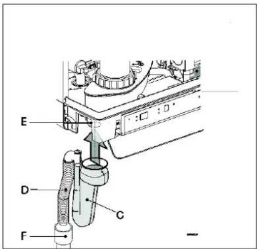

natural_image
Technical line drawing of a mechanical assembly with mounting brackets and bolts (no text or symbols)5 COLLEGAMENTI
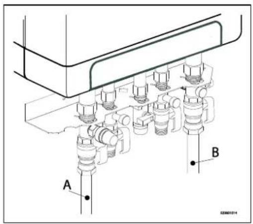
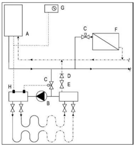
flowchart
graph TD
    A["Component A"] --> B["Valve"]
    B --> C["Actuator C"]
    C --> D["Flow Control"]
    D --> E["Component E"]
    E --> F["Valve F"]
    F --> G["Control G"]
    H["Component H"] --> I["Valve I"]
    I --> J["Actuator J"]
    J --> K["Flow Control"]
    K --> L["Component L"]
    L --> M["Control M"]
    M --> N["Flow Control"]
    N --> O["Component O"]
    O --> P["Control P"]
    P --> Q["Control Q"]
    Q --> R["Control R"]
    R --> S["Control S"]
    S --> T["Control T"]
    T --> U["Control U"]
    U --> V["Control V"]
    V --> W["Control W"]
    W --> X["Control X"]
    X --> Y["Control Y"]
    Y --> Z["Control Z"]
natural_image
Technical line drawing of a mechanical assembly with labeled component A (no text or symbols beyond label)
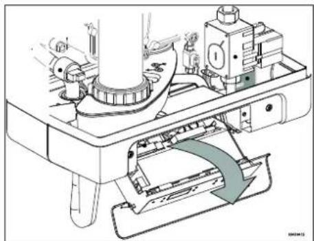
natural_image
Technical line drawing of a mechanical assembly with no visible text or symbolsnatural_image
Technical diagram of a pipe system with airflow indicators and support structures (no text or labels)natural_image
Technical line drawing of a mechanical component with labeled section A (no text or symbols beyond label)6.1.2 Fornitura ACS
natural_image
Technical line drawing of a mechanical device with threaded ports and internal components (no text or symbols)natural_image
Technical line drawing of a mechanical pump or motor assembly (no text or symbols)
line
| x | 100 % | 75 % | 50 % | 25 % | A | | ---- | ----- | ---- | ---- | ---- | ----- | | 0 | 7.0 | 4.0 | 2.0 | 0.5 | 0.0 | | 500 | 7.0 | 4.1 | 2.1 | 0.6 | 0.1 | | 1000 | 6.5 | 3.8 | 1.8 | 0.4 | 0.3 | | 1500 | 5.0 | 3.5 | 1.5 | 0.2 | 0.6 | | 2000 | 3.0 | 2.5 | 1.0 | 0.1 | 1.0 | | 2500 | 2.0 | 2.0 | 0.5 | 0.0 | 1.5 |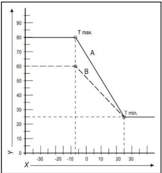
line
| X | Y | | ---- | ---- | | -10 | 80 | | -10 | 60 | | 25 | 25 |natural_image
Technical line drawing of a rectangular battery casing with labeled ports X and Y (no text or symbols beyond labels)8 DIFETTI
natural_image
Mechanical assembly diagram showing a rotating component with directional arrows indicating motion (no text or symbols)

9.1.3 Montaggio

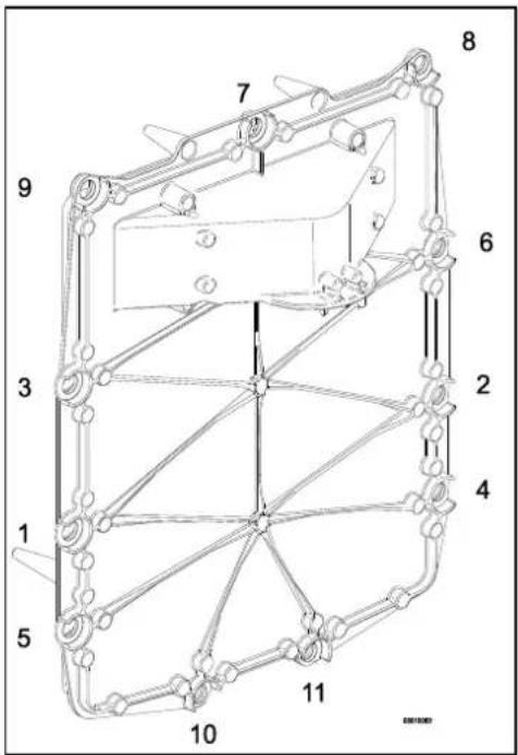
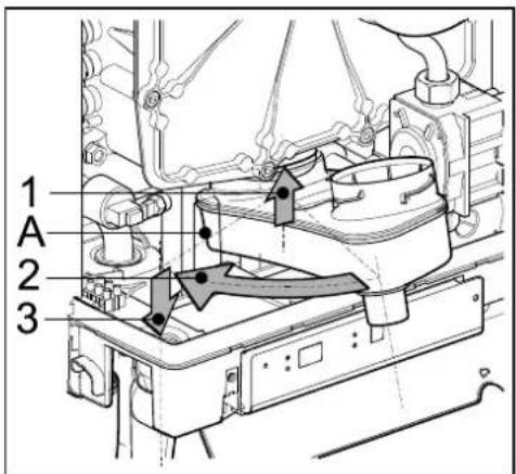
10 SPECIFICHE TECNICHE
G25 - Gas Naturale LL/L
G31 - GPL Propano
© 2022 Daikin Europe NVs
natural_image
Line drawing of a rectangular electronic device with a cylindrical top and mounting base (no text or symbols)natural_image
Technical line drawing of a mechanical assembly with labeled component A (no text or symbols beyond label)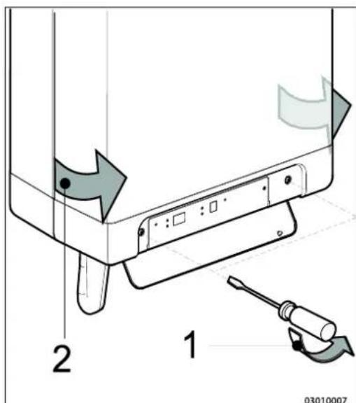
4.3 Montaż
natural_image
Technical line drawings of mechanical components with screws and bolts (no text or symbols)natural_image
Technical line drawing of an electrical enclosure with internal wiring and multiple water pumps (no text or symbols)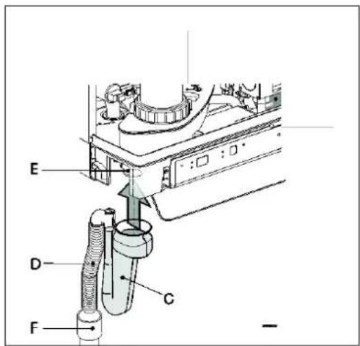
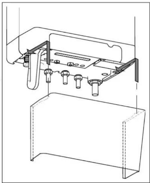
natural_image
Technical line drawing of a mechanical assembly with mounting brackets and fasteners (no text or symbols)5 PODŁĄCZANIE
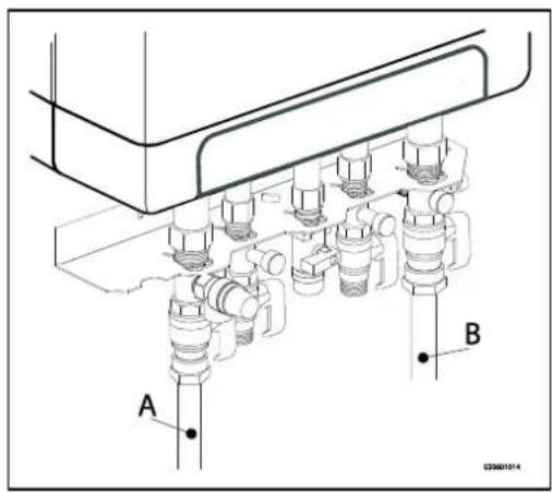
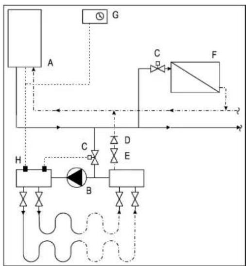
flowchart
graph TD
    A["Component A"] -->|Flow| B["Component B"]
    B -->|Control| C["Component C"]
    C -->|Flow| D["Component D"]
    D -->|Control| E["Component E"]
    E -->|Flow| F["Component F"]
    F -->|Control| G["Component G"]
    G -->|Flow| H["Component H"]
    H -->|Control| A
    style A fill:#f9f,stroke:#333
    style B fill:#ccf,stroke:#333
    style C fill:#cfc,stroke:#333
    style D fill:#fcc,stroke:#333
    style E fill:#cff,stroke:#333
    style F fill:#ffc,stroke:#333
    style G fill:#f9f,stroke:#333
    style H fill:#cfc,stroke:#333
natural_image
Technical line drawing of a mechanical assembly with labeled component A (no text or symbols present)

natural_image
Technical line drawing of a mechanical assembly with no visible text or symbols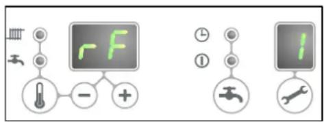
natural_image
Technical line drawing of a mechanical assembly with multiple pipes and a labeled component 'E' (no text or symbols beyond label)natural_image
Technical diagram of a pipe system with airflow indicators and support structures (no text or labels)6 ROZRUCH URZĄDZENIA I INSTALACJI
natural_image
Technical line drawing of a mechanical device with threaded ports and internal components (no text or symbols)natural_image
Technical line drawing of a mechanical pump or motor assembly (no text or symbols)
line
| x | 100 % | 75 % | 50 % | 25 % | A | B | | ---- | ----- | ---- | ---- | ---- | ---- | ---- | | 0 | 7 | 4 | 2 | 0.5 | 0 | 0 | | 500 | 7 | 4 | 2 | 0.5 | 0.5 | 0.5 | | 1000 | 7 | 4 | 2 | 0.5 | 1 | 1 | | 1500 | 6 | 3.5 | 2 | 0.5 | 2 | 2 | | 2000 | 4 | 3 | 2 | 0.5 | 3.5 | 3.5 | | 2500 | 2 | 2 | 2 | 0.5 | 4 | 4 | | 3000 | 2 | 2 | 2 | 0.5 | 4 | 4 |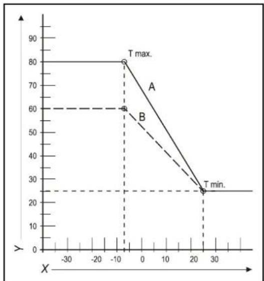
line
| X | Y | | ---- | ---- | | -10 | 80 | | -10 | 60 | | 20 | 25 |natural_image
Technical line drawing of a rectangular battery casing with labeled ports X and Y (no text or symbols beyond labels)8 USTERKI
natural_image
Mechanical assembly diagram showing a rotating component with directional arrows indicating motion (no text or symbols)9.1.1 Demontaż
9.1.2 Czyszczenie
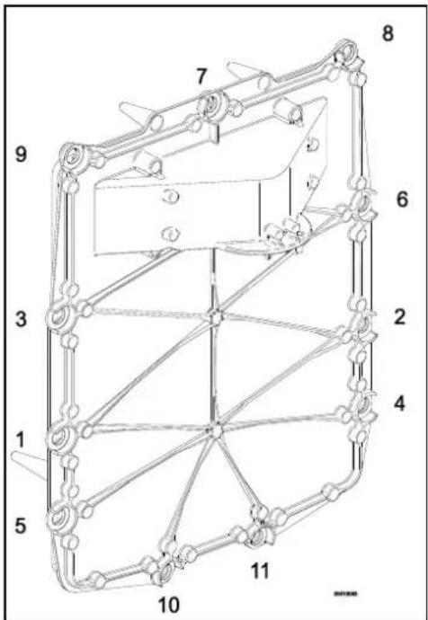
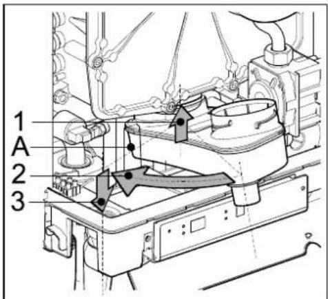
10 DANE TECHNICZNE
(1) G20 – Gaz ziemny E/H
G25 – gaz ziemny LL/L
G31 - LPG, Propan
© 2022 Daikin Europe NV
natural_image
Line drawing of a rectangular electronic device with a cylindrical top and mounting base (no text or symbols)7 Temperatura solicitada atingida
A. Bomba de CH
B. Válvula de gás
natural_image
Technical line drawing of a mechanical assembly with labeled component A (no text or symbols beyond label)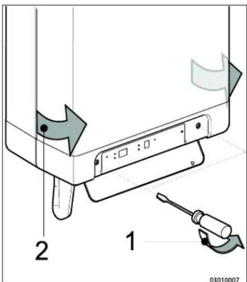
4.3 Montagem
natural_image
Technical line drawings of mechanical components with screws and bolts (no text or symbols)natural_image
Technical line drawing of a mechanical device with internal components and connectors (no text or symbols)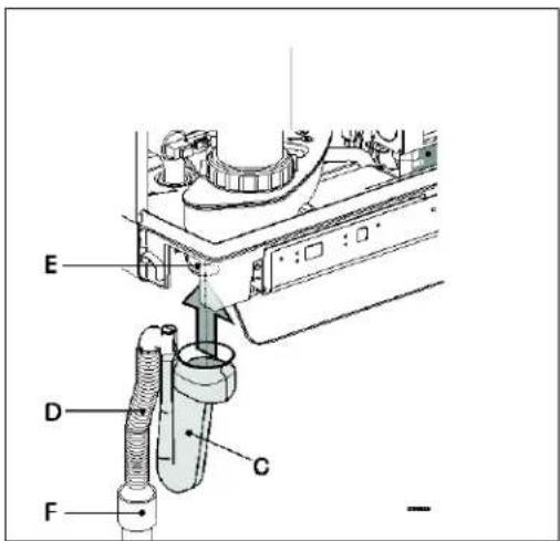
4.3.4 Aplicar a cobertura (opcional)
natural_image
Technical line drawing of a mechanical assembly with mounting brackets and bolts (no text or symbols)5 LIGAR
line
| X | A | B | C | | ---- | --- | --- | --- | | 0.0 | 1.0 | 1.0 | 1.0 | | 0.2 | 3.0 | 3.5 | 4.0 | | 0.4 | 5.0 | 6.0 | 7.0 | | 0.6 | 7.0 | 8.0 | 9.5 | | 0.8 | 9.0 | 10.0 | 11.5 | | 1.0 | 10.5 | 11.5 | 12.5 | | 1.2 | 11.5 | 12.5 | 13.5 | | 1.4 | 12.0 | 13.0 | 14.0 | | 1.6 | 12.5 | 13.5 | 14.5 | | 1.8 | 13.0 | 14.0 | 15.0 | | 2.0 | 13.5 | 14.5 | 15.5 |natural_image
Technical line drawing of a mechanical assembly with labeled component A (no text or symbols beyond label)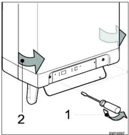
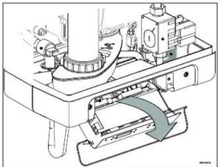
natural_image
Technical line drawing of a mechanical assembly with no visible text or symbolsnatural_image
Technical diagram of a mechanical assembly with multiple cylindrical components and a labeled component 'E' (no text or symbols beyond label)natural_image
Technical diagram of a pipe system with airflow indicators and a base unit (no text or labels)natural_image
Technical line drawing of a mechanical valve assembly (no text or symbols)natural_image
Technical line drawing of a mechanical pump or motor assembly (no text or symbols)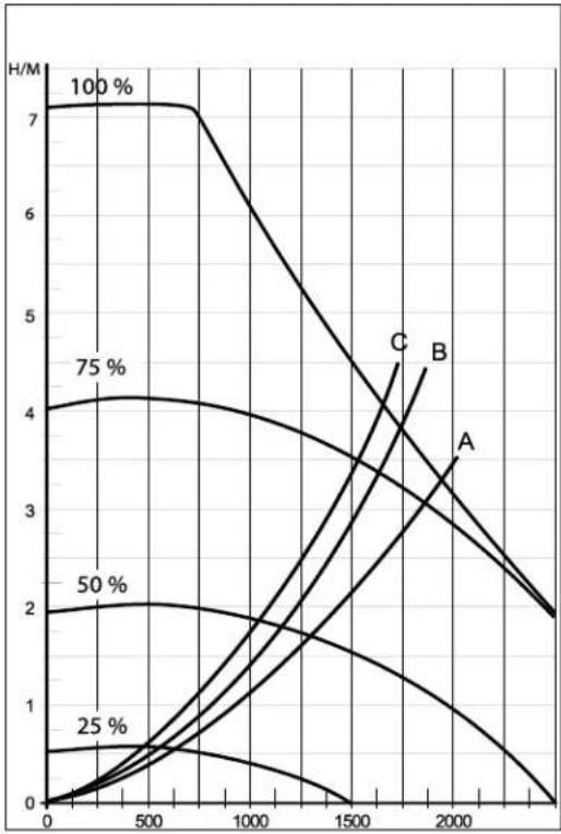
line
| x | y (Line 1) | y (Line 2) | y (Line 3) | y (Line 4) | y (Line 5) | y (Line 6) | y (Line 7) | | ---- | ---------- | ---------- | ---------- | ---------- | ---------- | ---------- | ---------- | | 0 | 7 | 4 | 2 | 1 | 0.5 | 0.2 | 0.1 | | 500 | 7 | 4 | 2 | 1 | 0.5 | 0.2 | 0.1 | | 1000 | 6 | 3.5 | 1.5 | 1 | 0.3 | 0.1 | 0.05 | | 1500 | 5 | 3 | 1 | 0.5 | 0.2 | 0.05 | 0.02 | | 2000 | 4 | 2.5 | 0.5 | 0.2 | 0.1 | 0.02 | 0.01 | | 2500 | 3 | 2 | 0.2 | 0.1 | 0.05 | 0.01 | 0.005 | | 3000 | 2 | 1.5 | 0.1 | 0.05 | 0.02 | 0.005 | 0.002 |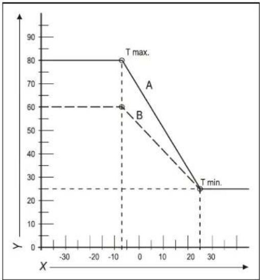
line
| X | Y | |---|---| | -10 | 80 | | -10 | 60 | | 25 | 25 |natural_image
Technical line drawing of a mechanical pump or valve assembly (no text or symbols)8 AVARIAS
natural_image
Technical diagram of a mechanical assembly with no visible text or symbols

9.1.3 Instalação

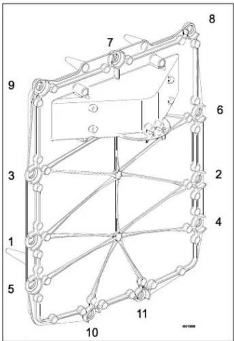

10 ESPECIFICAÇÕES TÉCNICAS
© 2022 Daikin Europe NV
natural_image
Line drawing of a rectangular electronic device with a cylindrical top and control buttons at the base (no text or symbols)A. Αντλία CH
B. Báva aερίου
natural_image
Technical line drawing of a mechanical assembly with labeled component A (no text or symbols beyond label)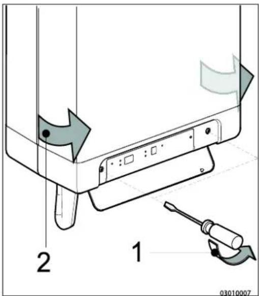
4.3 Συναρμολόγηση
natural_image
Technical line drawings of mechanical components with screws and bolts (no text or symbols)natural_image
Technical line drawing of a mechanical device with internal components and housing (no text or symbols)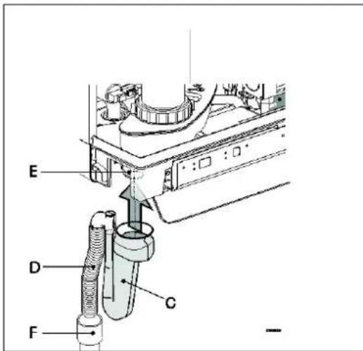
natural_image
Technical line drawing of a mechanical assembly with no visible text or symbols5 ΣΥΝΔΕΣΗ
natural_image
Technical line drawing of a mechanical assembly with labeled component A (no text or symbols beyond label)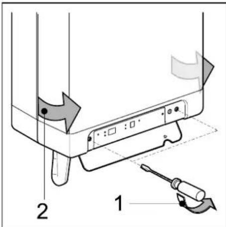

natural_image
Technical diagram of a pipe system with airflow indicators, showing a cyan pipe passing through a brick wall and connected to a battery (no text or symbols present)natural_image
Technical line drawing of a mechanical device with threaded shaft and mounting base (no text or symbols)natural_image
Technical line drawing of a mechanical pump or motor assembly (no text or symbols)
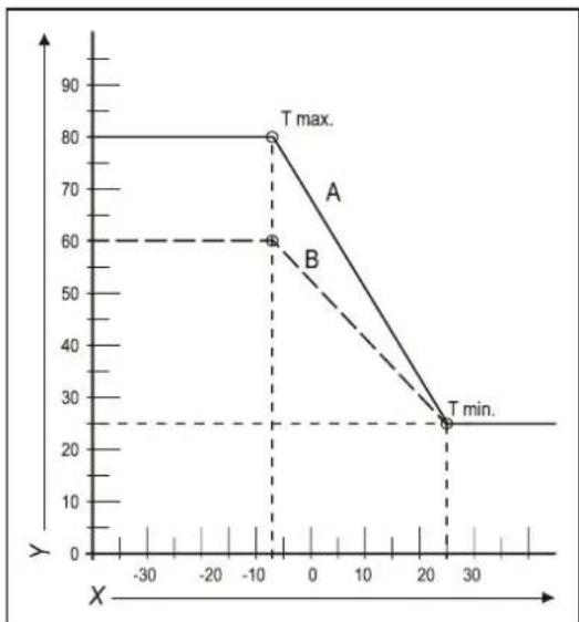
line
| Point | X | Y | |-------|------|-----| | A | -10 | 80 | | B | -10 | 60 | | T min.| 25 | 25 |natural_image
Technical line drawing of a mechanical pump or valve assembly (no text or symbols)8 ΔΥΣΛΕΙΤΟΥΡΓΙΕΣ
natural_image
Mechanical assembly diagram showing a rotating component with directional arrows (no text or symbols)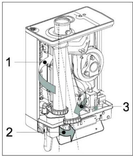
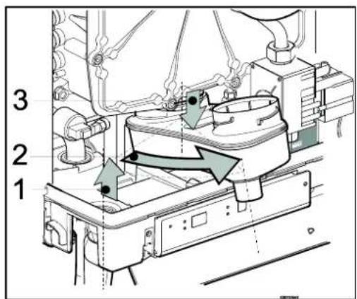
9.1.3 Εφαρμογή

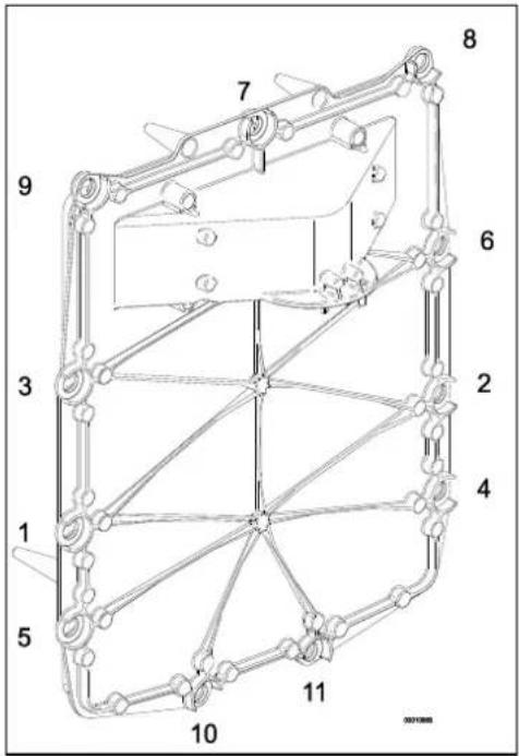
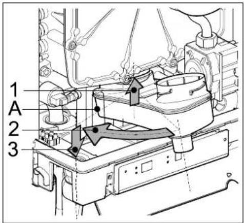
- EKOMBG22ABV1
- EKOMBG28ABV1
- EKOMBG33ABV1
- Safety instructions 5
- Unit description 5
- Main components 9
- Installation 11
- Connecting 16
- Commissioning the unit and the Installation 35
- Setting and adjustment 38
- Malfunctions
- Maintenance
- Technical specifications
- 10
- These installation instructions
- Symbols
- CAUTION
- IMPORTANT
- Service and technical support for the installer
- Identification of the product
- SAFETY INSTRUCTIONS
- UNIT DESCRIPTION
- General
- Functioning
- Operating modes
- Standby
- Post-running CH
- Requested temperature reached
- Selftest
- Ventilating
- Igniting
- CH-operation
- Domestic hot water operation
- Heating up unit
- PC Interface
- Test programs
- Frost protection
- Note
- MAIN COMPONENTS
- INSTALLATION
- Installation measurements
- Installation space
- Installing in kitchen cabinet
- Removing cover plate and front panel
- Assembly
- Assembling suspension strip and assembly bracket
- Assembling bottom connection set
- Assembling the unit
- Apply cover plate (optional)
- CONNECTING
- Connecting CH installation
- The CH installation must be fitted with:
- Thermostatic radiator taps
- Underfloor heating
- Underfloor heating with pump
- Connection diagram underfloor heating
- Underfloor heating without pump
- Dividing CH installation in groups in case of additional heat sources
- Operating principle
- Installation instructions
- Connecting DHW installation
- Comments
- Resistance graph tap circuit unit
- Connecting electronically
- Connect room thermostat
- Room thermostat on/off
- Modulating room thermostat, Open Therm
- Modulating room thermostat, wireless
- Testing the connection between the unit and the RF room thermostat
- Undo the appointment of an RF room thermostat to the CH boiler.
- Outdoor temperature sensor
- Connecting gas
- Flue and air supply duct
- Concentric connection 60/100
- Concentric connection 80/125
- Parallel connection 80/80
- Outlet systems
- Flue material
- Connection to a flue system without air inlet (B23, B33)
- General assembly
- Permitted pipe lengths at parallel air supply and flue tube systems
- Connection to a sealed flue system.
- Pipe lengths
- Permitted pipe lengths in concentric flue tube systems
- General assembly:
- Permitted pipe lengths at parallel air supply and flue tube systems
- Note:
- Free in the market available flue gas materials (C63).
- Securing the flue system
- Air supply from the facade and a roof outlet with communal exhaust system
- Communal combustible gas outlet
- Combined flue outlet/air inlet system
- Concentric horizontal flue gas outlet, vertical part air-surrounded by shaft
- General
- Permitted pipe length and system requirements
- COMMISSIONING THE UNIT AND THE INSTALLATION
- Filling and air purge of unit and installation
- CH system
- WARNING
- DHW provision
- Gas supply
- Commissioning the unit
- Reading
- Operating
- Switching off the unit
- Frost protection
- SETTING AND ADJUSTMENT
- Direct via operating panel
- Unit on/off
- Tap comfort
- Resetting
- Change settings of the various functions:
- Maximum CH leaving water temperature
- Tap water temperature
- Parameter settings via the service code
- Example: Change maximum CH power
- Setting maximum CH power
- Set pump capacity
- Pressure loss graph unit CH side
- Weather dependent regulation
- Fuel line graph
- Conversion to different type of gas
- Work on gas carrying parts may only be carried out by a certified installer.
- Converting the dosing ring
- Gas/air regulation
- Setting gas/air regulation
- Checking the carbon dioxide setting
- Adjusting the carbon dioxide setting
- Show last malfunction
- Malfunction codes
- Other faults
- Boiler controller is noisy when igniting
- Boiler controller resonates
- No heating (CH)
- The power is reduced
- CH is not reaching correct temperature
- No domestic hot water
- DHW is not reaching the correct temperature
- CH installation stays warm unwanted
- A-label pump LED flashes intermittently red/green
- A-label pump LED flashes red
- Disassembly
- Cleaning
- Fitting
- Technical Product Fiche in accordance to CELEX-32013R0811
- Electrical diagram
- WARRANTY CONDITIONS
- Environment
- Use as intended
- INHALTSVERZEICHNIS
- Installationsort
- Montage
- ANSCHLIEßEN
- Modulierendes Funk-Raumthermostat
- INBETRIEBNAHME DES GERÄTS UND DER INSTALLATION
- STÖRUNGEN
- Reinigen
- TECHNISCHE DATEN
- Assemblage
- CONNEXION
- Thermostat d'ambiance modulant, sans fil
- MISE EN SERVICE DE L'UNITE ET DE L'INSTALLATION
- DYSFONCTIONNEMENTS
- Montage
- Toestel monteren
- AANSLUITEN
- Modulerende kamerthermostaat, draadloos
- IN BEDRIJF STELLEN VAN HET TOESTEL EN DE INSTALLATIE
- STORINGEN
- Technical Product Fiche in accordance to CELEX-32013R0811
- Montaggio
- Montaggio del B-pack
- COLLEGAMENTI
- Fornitura ACS
- DIFETTI
- Montaggio
- SPECIFICHE TECNICHE
- Montaż
- PODŁĄCZANIE
- ROZRUCH URZĄDZENIA I INSTALACJI
- USTERKI
- Demontaż
- Czyszczenie
- Montagem
- Aplicar a cobertura (opcional)
- LIGAR
- AVARIAS
- Instalação
- Συναρμολόγηση
- ΣΥΝΔΕΣΗ
- ΔΥΣΛΕΙΤΟΥΡΓΙΕΣ
- Εφαρμογή
Brand : DAIKIN
Model : EKOMBG22ABV1
Category : Boiler