AC1 - Vacuum Cleaner Ultenic - Free user manual and instructions
Find the device manual for free AC1 Ultenic in PDF.


User questions about AC1 Ultenic
0 question about this device. Answer the ones you know or ask your own.
Ask a new question about this device
Download the instructions for your Vacuum Cleaner in PDF format for free! Find your manual AC1 - Ultenic and take your electronic device back in hand. On this page are published all the documents necessary for the use of your device. AC1 by Ultenic.
USER MANUAL AC1 Ultenic
natural_image
Line drawing of a handheld vacuum cleaner with attached housing and handle (no text or symbols)User Manual
Cordless Wet Dry Vacuum Cleaner
Model: AC1
Contents
EN IT
Precautions 01
About Your Product 03
Product Use 05
Product Maintenance 08
Troubleshooting 11
Product Specification 12
Please read the following precautions carefully before using this appliance:
- Use only indoors on non-carpeted floor surfaces such as vinyl, tile, sealed wood, etc. Be careful not to run over loose objects or carpet edges.
- Use only the battery pack and charger specified by the Ultenic. Using any other battery pack may cause personal injury and fire risk.
- Do not use your product to clean flammable or chemical products such as gasoline, strong acids, or strong alkalis; do not use WashVac AC1 to pick up sharp objects such as metal nails, glass fragments, and needles.
- Do not touch the charger and the plug with wet hands.
- Do not use WashVac AC1 without the filter.
- Do not use with a damaged power cable or plug. If WashVac AC1 has been dropped, damaged, left outdoors, dropped into water, or failed to work properly, contact our service center.
- Be extra careful when cleaning on the stairs.
- Keep your hair, clothing, fingers, and all parts of your body away from openings and moving parts.
- Do not use WashVac AC1 when the water depth exceeds 5 mm.
- Turn off this appliance before making any adjustments, replacing accessories, or storing this appliance.
- WashVac AC1 can only be used, charged, and stored in a dry room where the temperature is higher than 4^ but lower than 35^ .
- If you accidentally drop the battery, liquid may run out of the battery. Avoid touching it. If touched accidentally, rinse with water. If liquid gets into your eyes, seek medical help.
- If this appliance overheats, makes abnormal noise, produces abnormal smell or leaks, stop using it immediately.
- For long-term storage, please turn off WashVac AC1 and disconnect the power from the socket.
- Be sure to clean the dirty water tank after each use to avoid clogging, which will result in poor suction, motor overheating or shortened service life of this appliance.
- All data and technical descriptions in this manual are based on test results from Ultenic laboratory tests and Ultenic reserves the right of final interpretation.
FCC Statement
This device complies with Part 15 of the FCC Rules. Operation is subject to the following two conditions: (1) This device may not cause harmful interference, and (2) this device must accept any interference received, including interference that may cause undesired operation.
Warning: Changes or modifications not expressly approved by the party responsible for compliance could void the user's authority to operate the equipment.
Note: This equipment has been tested and found to comply with the limits for a Class B digital device, pursuant to Part 15 of the FCC Rules. These limits are designed to provide reasonable protection against harmful interference in a residential installation. This equipment generates, uses, and can radiate radio frequency energy and, if not installed and used in accordance with the instructions, may cause harmful interference to radio communications. However, there is no guarantee that interference will not occur in a particular installation. If this equipment does cause harmful interference to radio or television reception, which can be determined by turning the equipment off and on, the user is encouraged to try to correct the interference by one or more of the following measures: (1) Reorient or relocate the receiving antenna. (2) Increase the separation between the equipment and receiver. (3) Connect the equipment into an outlet on a circuit different from that to which the receiver is connected. (4) Consult the dealer or an experienced radio/ TV technician for help.
About Your Product
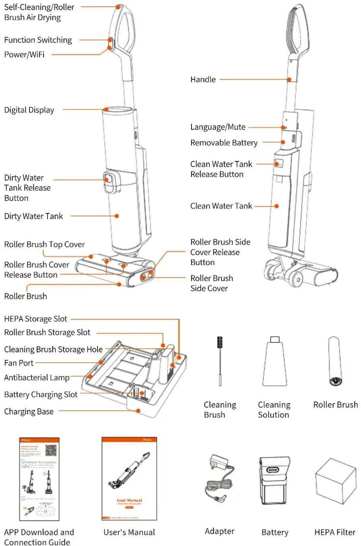
Self-Cleaning/Roller
Brush Air Drying
Function Switching
Power/WiFi
Digital Display
Dirty Water
Tank Release
Button
Dirty Water Tank
Roller Brush Top Cover
Roller Brush Cover
Release Button
Roller Brush
HEPA Storage Slot
Roller Brush Storage Slot
Cleaning Brush Storage Hole
Fan Port
Antibacterial Lamp
Battery Charging Slot
Charging Base
APP Download and Connection Guide
User's Manual
Cleaning
Brush
Cleaning Solution
Roller Brush
Adapter
Battery
HEPA Filter
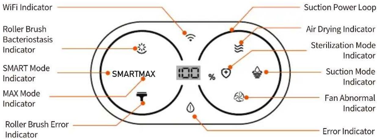
Display Indicator Diagram
text_image
WiFi Indicator Roller Brush Bacteriostasis Indicator SMART Mode Indicator MAX Mode Indicator Roller Brush Error Indicator Suction Power Loop Air Drying Indicator Sterilization Mode Indicator Suction Mode Indicator Fan Abnormal Indicator Error Indicator SMARTMAXAccessories
Cleaning Tool:
Can be used to clean dirty water tank and tube.
Cleaning Solution:
It can remove dirt, grease and tough stains from hard floor surfaces such as tile, marble, sealed hardwood floors, etc. Add a bottle cap of cleaning solution (10ml) to each water tank filled with clean water, in a ratio of 1:100.
Note: Do not add non-special cleaning solution to avoid corrosion of the water tank.
HEPA Filter:
The filtered mounted on the sewage tank, dirty water and dust are discharged into the air to reduce air pollution and avoid water entering the motor and damaging it.
Roller Brush:
The roller head with bristles can be used for vacuuming and washing at the same time.(If there is a lot of hair at home, you can replace the composite roller brush to clean)

natural_image
Line drawings of four different objects: a toothbrush, a tube, a cube, and a rolled roller (no text or symbols)Cleaning Tool Cleaning Solution HEPA Filter Roller Brush
Product Use
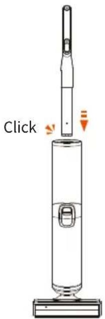
Assembly
- To assemble the handle, insert it directly into the appliance until you hear a click.
- To disassemble the handle, use a tool (such as a screwdriver) to release the handle by pressing the spring, and then lift the released handle from the appliance.
text_image
Click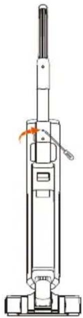
natural_image
Line drawing of a vacuum cleaner with handle and control panel (no text or symbols)Charging
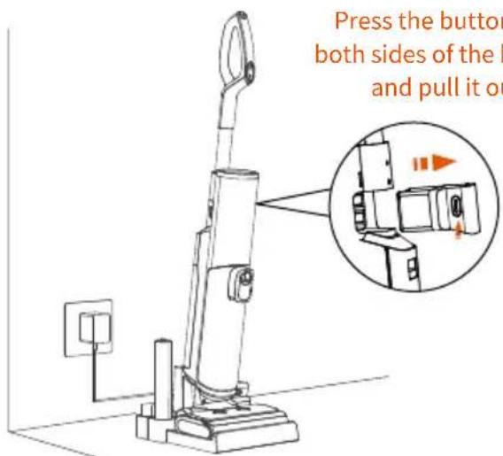
- Put the device on the charging stand first, then plug in the charger to charge. It may take 4 hours for a full charge.
(The battery can also be removed and separately charged on the base, but it must be ensured the charging slot is dry.)
- To avoid tripping hazards, please place the appliance and the charging base close to a wall while charging.
Note: When not in use for a long period of time, the appliance must be charged once every month for optimal performance.
text_image
Press the button both sides of the l and pull it on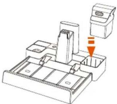
natural_image
Technical line drawing of a mechanical assembly with a downward arrow indicating a component (no text or symbols present)Battery can be directly charged on the base
Operation
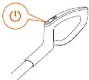
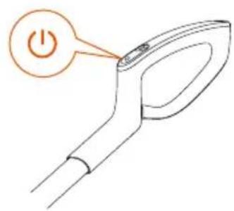
- Press the power button and the appliance will start in SMART by default. Press it again to turn off.
text_image
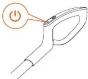
Diagram of a power switch with an orange button labeled 'Power' pointing to the switch handle.- Long-press the power button for 5s to configure the network. For operation instructions, please follow the "APP Download and Connection Guide
text_image
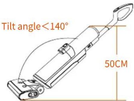
Diagram of a power switch with an orange button labeled 'Power' pointing to the switch handle- Do not recline the appliance more than 140^ to prevent water leakage. (The appliance cannot be fully extended when the gap under the furniture is less than 50cm)
text_image
Tilt angle<140° 50CM- Press the function button to switch among SMART, MAX, Sterilization and Suction Modes.
natural_image
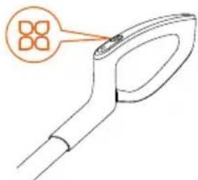
Line drawing of a tool handle with a highlighted square icon (no text or symbols)- Press the mute button for 5s to turn the sound on/off. Press the Language/Mute button to switch languages (In sequence: English, German, French, Italian and Spanish). Long-press for 3s to turn on/off the voice.
natural_image
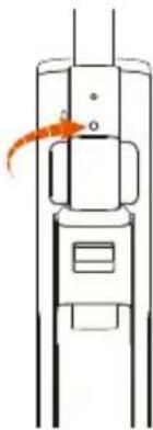
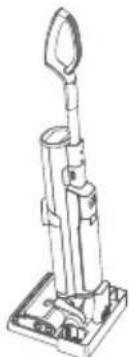
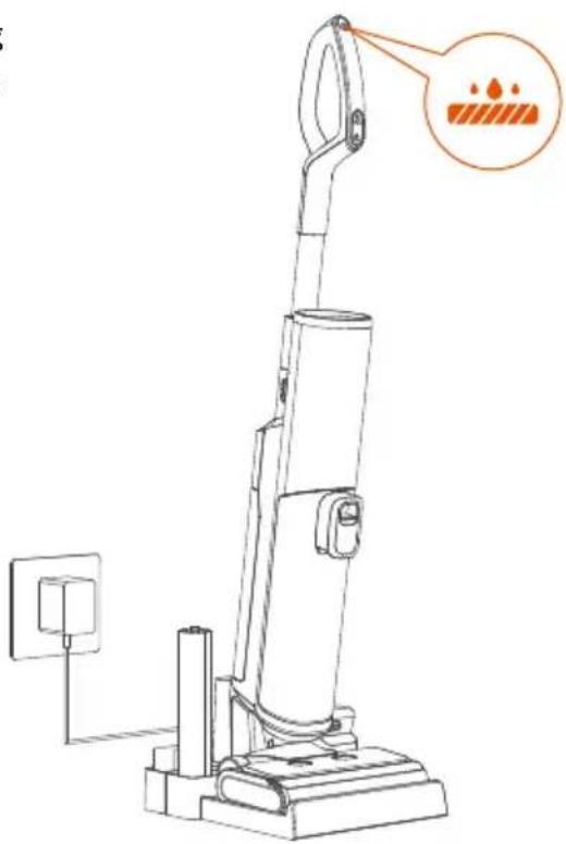
Simple line drawing of a vertical cylindrical device with an orange arrow pointing to the top section (no text or symbols)- After use, place the appliance vertically on the charging base for charging and storage.
natural_image
Technical line drawing of a mechanical device with a conical top and base (no text or symbols)-
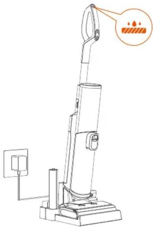
When the appliance is charged on the charging base, you can press the self-cleaning button to automatically clean the roller brush and tube. After the self-cleaning, the Sterilization UV Light and fan will be turned on automatically after a delay of 5s.
-
When the appliance is charged on the charging base, long-press the self-cleaning button for 5s to turn on/off the antibacterial lamp and fan.
natural_image
Line drawing of a vacuum cleaner with an orange annotation highlighting a textured surface (no text or symbols present)Cleaning Mode
SMART SMART Mode
In SMART mode, the appliance automatically applies different suction power and sprays the appropriate amount of water according to the degree of dirt on the floor detected by the sensor.
MAX MAX Mode
In MAX mode, the appliance will apply max suction and spray max amount of water for deeper cleaning.

Sterilization Mode
In Sterilization mode, the appliance will make sterilizing solution and work in SMART mode.

Suction Mode
In Suction mode, the appliance only absorbs liquids and does not spray water.
Product Maintenance
To get the best performance and prevent odors, thoroughly clean and dry the clean water tank, dirty water tank, filters, cleaning tool, roller brush and roller brush cover, Roller brush side cover after each use.
After maintenance, place the appliance vertically on the charging base and store them in a dry place indoors.
Main Body
Before cleaning, stop the appliance and unplug the power plug. Clean the surface with water or neutral detergent and wring out the cloth to prevent water from entering the appliance.
text_image
Diagram of a power switch with an orange button labeled 'Power' pointing to the switch handle.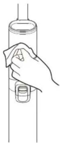
natural_image
Line drawing of a hand cleaning a cylindrical object with a cloth (no text or symbols)Dirty Water Tank
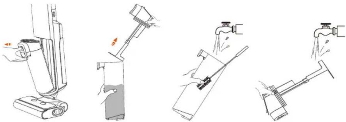
When the dirty water reaches the Max line, this appliance will stop working while displaying a reminder and playing a voice. Remove the tank, use a cleaning brush to remove residual debris, and flush the tank interior. (Pay attention to the direction of the hand)
natural_image
Four-step diagram showing a hand operating a cleaning machine, pouring liquid from a bottle into a bag (no text or symbols present)① ② ③ ④
Roller brush self-cleaning
- After use, put this appliance back to the charging dock for self-cleaning. Press the self-cleaning button to start the process.
- After completion, you will hear the voice prompt “Cleaning completed, please clean the dirty water tank”.
Note: Before self-cleaning, the battery level should exceed 20%, the dirty water tank should be emptied, and the water level of the clean water tank should exceed 40%.
natural_image
Line drawing of a vacuum cleaner with a close-up view showing the blade and base (no text or symbols)Filter
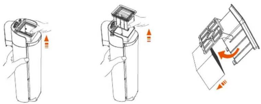
Grab the sides of the filter and pull it up. Wash it under running water, and then install it back into the machine until it is dry.
* Your appliance has a spare filter for easy replacement.
① ② ③
Roller brush top cover
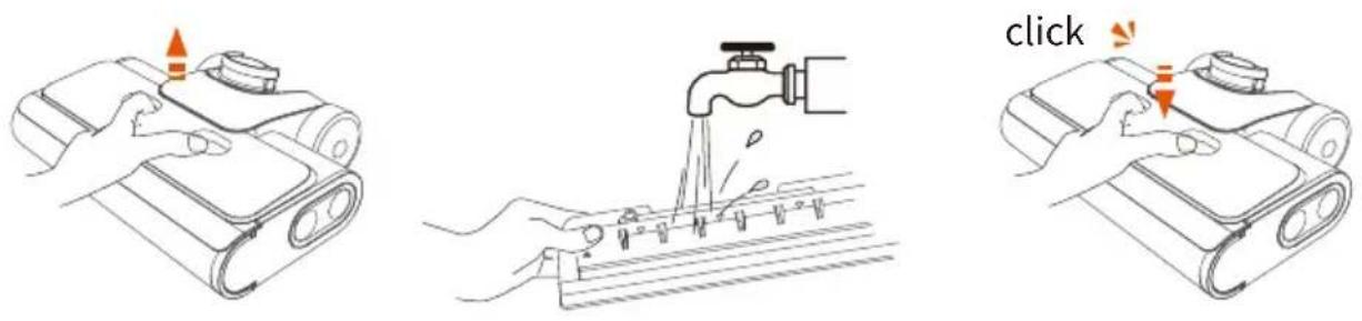
- Grab the front handle while holding down the button, and pull up to remove it.
- Wash it with water.
- Make sure the cover is locked in place when installed, to avoid water leakage.
Roller Brush
- Hold down the right button to remove the cover, and then pull out the Roller Brush to the right.
- Remove hair and debris from the Roller Brush with a cleaning tool, and then rinse with water.
- Remove hair and debris from the Roller Brush box and tube with the cleaning brush.
Note: Your appliance has a spare Roller Brush for easy replacement.

Troubleshooting
| Problem | Possible cause | Solution |
| The appliance is not turned on | Automatic overheating protection | Restart after cooling down |
| Can not run after turning on Voice prompt: standby | The machine stands upright | Step on the roller brush top, press down the handle and enter the working state |
| All lights are off during operation | Battery overheat or malfunction | Restart after cooling down |
| Error indicator flashes Voice prompt: Check the roller brush | Roller brush is blocked; Roller brush not installed or absent | Clean the roller brush; Install the roller brush correctly |
| Error indicator flashes Voice prompt: Water shortage in clean water tank, please add water | Clean water tank is empty | Add water or liquid to the clean water tank and reinstall it |
| Error indicator flashes Voice prompt: Dirty water tank full, please clean up in time to avoid odor | Dirty water has reached the Max line | Empty the dirty water and reinstall the dirty water tank |
| Voice prompt: check the dirty water tank | Dirty water tank absent Install the dirty water tank correctly | |
| WiFi indicator OFF | WiFi disconnected | Follow the instructions in the APP to connect to WiFi |
| Battery level indicator flashes Voice prompt: insufficient power, please charge | Low battery | Charge the appliance or restart it |
| Weak suction | The filter is not installed; The filter is dirty or the tube is blocked. | Install the filter; Clean the filter and tube |
| High noise of the motor | The filter is not installed; The filter is dirty or the tube is blocked. | Install the filter; Clean the filter and tube |
| Error indicator flashes Voice prompt: Fan error | Motor fault | Shut down and restart after 2 minutes. If it still doesn't work, please contact the customer service: support@Ultenic.com |
Product Specification
| Product model | WashVac AC1 |
| Charging input | 100~240V |
| Voltage and electric quantity | 21.6V, 4000mAh |
| Rated power | 200W |
| Running time | SMART: ~45min MAX: ~25min |
| Charging time | 4h |
| Water flow rate | 45~200mL/min |
| Clean Water Tank Capacity | 1L |
| Dirty Water Tank Capacity | 1L |
| Water Resistant | IPX4 |
Vorsichtsmaßnahmen
natural_image
Line drawings of four different objects: a brush, a tube, a cube, and a rolled paper (no text or symbols)natural_image
Line drawing of a vacuum cleaner with handle and base mount (no text or symbols)Aufladen
natural_image
Technical line drawing of a mechanical assembly with a component and an arrow indicating a downward motion (no text or symbols present)text_image
Diagram of a power switch with an orange button labeled 'Power' pointing to the handletext_image
Diagram of a power switch with an orange button labeled 'Power' pointing to the switch handlenatural_image
Line drawing of a tool handle with a highlighted square component (no text or symbols)natural_image
Line drawing of a vertical device with an orange arrow pointing to the top section (no text or symbols)natural_image
Technical line drawing of a mechanical device with a handle and base (no text or symbols)natural_image
Line drawing of a vacuum cleaner with a close-up view showing the handle and base, no text or symbols present.Reinigungsmodus
SMART SMART-Modus
text_image
Diagram of a power switch with an orange power button labeled in Chinese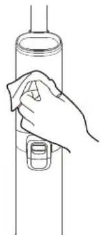
natural_image
Line drawing of a hand cleaning a cylindrical object with a cloth (no text or symbols)Schmutzwassertank
natural_image
Four-step diagram showing a hand operating a cleaning machine, pouring liquid from a bottle into a spray bottle (no text or symbols present)① ② ③ ④
natural_image
Line drawing of a vacuum cleaner with an orange warning icon and label (no text or symbols on the device itself)Filter
natural_image
Line drawings showing three different cleaning or packaging methods: a portable device, a mechanical component with a handle, and a drain with water pouring (no text or symbols present)Störungsbehebung
text_image
User Manual #POTATO FOR YOUR Copyright © 2014natural_image
Line drawing of a vacuum cleaner with handle and spool (no text or symbols)Chargement
natural_image
Technical line drawing of a mechanical assembly with a highlighted component (no text or symbols)text_image
Diagram of a power switch with an orange button labeled 'Power' pointing to the handletext_image
Diagram of a power switch with an orange button labeled 'Power' pointing to the switch handlenatural_image
Line drawing of a tool handle with a highlighted square symbol (no text or labels)natural_image
Simple line drawing of a vertical device with an orange arrow pointing to the left side (no text or symbols)natural_image
Technical line drawing of a mechanical device with a lever and base (no text or symbols)natural_image
Line drawing of a vacuum cleaner with an orange annotation highlighting a textured surface (no text or symbols present)Mode de nettoyage
SMART Mode SMART
text_image
Diagram of a power switch with an orange button labeled 'Power' pointing to the switch's tip.
natural_image
Line drawing of a hand cleaning a cylindrical object with a cloth (no text or symbols)natural_image
Four-step diagram showing a hand holding a device, pouring liquid from a bottle into a container, and finally extending a lever to handle a bucket (no text or symbols present)① ② ③ ④
natural_image
Line drawing of a vacuum cleaner with a close-up view showing its mounting base and heat sink (no text or symbols present)Filtre
natural_image
Three-step line drawings of a device being handled, showing hand positioning, internal components, and cleaning steps (no text or symbols)Dépannage
text_image
POT ECONOMICS VEGETABLES SLICE File: To the following table is to be used in the POT ECONOMICS database. It is not used to use the other database. The database is used to create a new database (e.g., a new database with a new database containing a new database). The database is used to create a new database (e.g., a new database containing a new database). The database is used to create a new database (e.g., a new database containing a new database). The database is used to create a new database (e.g., a new database containing a new database). The database is used to create a new database (e.g., a new database containing a new database). The database is used to create a new database (e.g., a new database containing a new database). The database is used to create a more complete or complete version of the database. Table 1 The table is created using the 'POT ECONOMICS' database as an example of the existing database design. The database contains two distinct databases: one for the existing database and one for the newer ones. The existing database contains three databases, each represented by a separate icon. The newer database contains four databases, each represented by a separate icon. The existing database contains five databases, each represented by a separate icon. The newer database contains six databases, each represented by a separate icon. The existing database contains seven databases, each represented by a separate icon. The newer database contains eight databases, each represented by a separate icon. The existing database contains nine databases, each represented by a separate icon. The newer database contains ten databases, each represented by a separate icon. The existing database contains ten databases, each represented by a separate icon. The newer database contains ten databases, each represented by a separate icon. The existing database contains ten databases, each represented by a separate icon. The newer database contains ten databases, each represented by a separate icon. The existing database contains ten databases, each represented by a separate icon. The newer database contains ten databases, each represented by a separate icon. The existing database contains ten databases, each represented by a separate icon. The newer database contains ten databases (e.g., 100), 1000, 10000, and 10000 respectively. Table 2 The table is created using the 'POT ECONOMICS' database as an example of the existing database design. The database contains two distinct databases: one for the existing database and one for the newer database. The existing database contains three databases (e.g., 100), 1000, and 1000 respectively. The existing database contains four databases (e.g., 1000, 10000, 10000) and one for the newer database (e.g., 1000, 10000, 10000) respectively. Table 3 The table is created using the 'POT ECONOMICS' database as an example of the existing database design. The database contains two distinct databases: one for the existing database and one for the newer database. The existing database contains three databases (e.g., 100), 1000, and 1000 respectively. The existing database contains four databases (e.g., 1000, 10000, 1012), and one for the newer database (e.g., 1000, 10000, 1012) respectively. Table 4 The table is created using the 'POT ECONOMICS' database as an example of the existing database design. The database contains two distinct databases: one for the existing database and one for the newer database. The existing database contains three databases (e.g., 100), 1000, and 1000 respectively. The existing database contains four databases (e.g., 1000, 10000, 1028), and one for the newer database (e.g., 1000, 10000, 1028) respectively. Table 5 The table is created using the 'POT ECONOMICS' database as an example of the existing database design. The database contains two distinct databases: one for the existing database and one for the newer database. The existing database contains three databases (e.g., 100), 1000, and 1012 respectively. Table 6 The table is created using the 'POT ECONOMICS' database as an example of the existing database design. The database contains two distinct databases: one for the existing database and one for the newer database. The existing database contains three databases (e.g., 100), 1000, and 1012 respectively. Table 7 The table is created using the 'POT ECONOMICS' database as an example of the existing database design. The database contains two distinct databases: one for the existing database and one for the newer database. The existing database contains three databases (e.g., 100), 1000, and 1012 respectively. Table 8 The table is created using the 'POT ECONOMICS' database as an example of the existing database design. The database contains two distinct databases: one for the existing database and one for the newer database. The existing database contains three databases (e.g., 100), 1000, and 1012 respectively. Table 9 The table is created using the 'POT ECONOMICS' database as an example of the existing database design. The database contains two distinct databases: one for the existing database and one for the newer database. The existing database contains three databases (e.g., 100), 1000, and 1012 respectively. Table 10 The table is created using the 'POT ECONOMICS' database as an example of the existing database design. The database contains two distinct databases: one for the existing database and one for the newer database. The existing database contains three databases (e.g., 100), 1000, and 1012 respectively. Table 11 The table is created using the 'POT ECONOMICS' database as an example of the existing database design. The database contains two distinct databases: one for the existing database and one for the newer database. The existing database contains three databases (e.g., 100), 1000, and 1012 respectively. Table 12 The table is created using the 'POT ECONOMICS' database as an example of the existing database design. The database contains two distinct databases: one for the existing database and one for the newer database. The existing database contains three databases (e.g., 100), 1000, and 1012 respectively. Table 13 The table is created using the 'POT ECONOMICS' database as an example of the existing database design. The database contains two distinct databases: one for the existing database and one for the newer database. The existing database contains three databases (e.g., 100), 1000, and 1012 respectively. Table 14 The table is created using the 'POT ECONOMICS' database as an example of the existing database design. The database contains two distinct databases: one for the existing database and one for the newer database. The existing database contains three databases (e.g., 100), 1000, and 1012 respectively. Table 15 The table is created using the 'POT ECONOMICS' database as an example of the existing database design. The database contains two distinct databases: one for the existing database and one for the newer database. The existing database contains three databases (e.g., 100), 1000, and 1012 respectively. Table 16 The table is created using the 'POT ECONOMICS' database as an example of the existing database design. The database contains two distinct databases: one for the existing database and one for the newer database. The existing database contains three databases (e.g., 100), 1000, and 1012 respectively. Table 17 The table is created using the 'POT ECONOMICS' database as an example of the existing database design. The database contains two distinct databases: one for the existing database and one for the newer database. The existing database contains three databases (e.g., 100), 1000, and 1012 respectively. Table 18 The table is created using the 'POT ECONOMICS' database as an example of the existing database design. The database contains two distinct databases: one for the existing database and one for the newer database. The existing database contains three databases (e.g., 100), 1000, and 1012 respectively. Table 19 The table is created using the 'POT ECONOMICS' database as an example of the existing database design. The database contains two distinct databases: one for the existing database and one for the newer database. The existing database contains three databases (e.g., 102), 128, and 288 respectively. Table 20 The table is created using the 'POT ECONOMICS' Database as an example of the existing database design. The data includes two data points per row: one for each data point.text_image
User Manual Product Name: User Manualnatural_image
Line drawing of a vacuum cleaner with handle and base mount (no text or symbols)Ricarica
natural_image
Technical line drawing of a mechanical assembly with a highlighted component (no text or symbols)text_image
Diagram of a power switch with an orange button labeled 'Power' pointing to the handlenatural_image
Simple line drawing of a tool handle with a highlighted square containing four squares (no text or symbols)text_image
Diagram of a power switch with an orange button labeled 'Power' pointing to the switch handle.natural_image
Line drawing of a vertical cylindrical device with an orange arrow pointing to its top section (no text or symbols)natural_image
Technical line drawing of a mechanical device with a cylindrical component and a protruding horn (no text or symbols)natural_image
Line drawing of a vacuum cleaner with a warning icon and label (no text or symbols on the device itself)Modalità di pulizia
SMART SMART mode
natural_image
Line drawing showing a hand holding a cleaning tool next to a device with a power button (no text or symbols)natural_image
Four-step diagram showing a hand holding a device, pouring liquid from a bottle into a cleaning or cleaning tool (no text or symbols present)① ② ③ ④
Spazzola a rullo autopulente
natural_image
Line drawing of a vacuum cleaner with a close-up view showing the handle and base (no text or symbols)Filtro
natural_image
Three-step diagram showing a device being handled, with arrows indicating motion direction (no text or symbols)① ② ③
natural_image
Three-step line drawings of a cleaning device: opening, pressing a clip, and pouring liquid into a tap (no text or symbols)text_image
SPTA WATER DRAIN CIVILICUS and the following: 1. The first part of the diagram is to be used to create a device from the top of the chart. The second part is to be used to create a device from the bottom of the chart. The third part is to be used to create a device from the top of the chart. The fourth part is to be used to create a device from the bottom of the chart. The second part is also used to create a device from the top of the chart. The third part is used to create a device from the bottom of the chart. The second part is used to create a device from the top of the chart. The third part is used to create a device from the bottom of the chart. The second part is used to create a device from the top of the chart. The third part is used to create a device from the bottom of the chart. The second part is used to create a device from the top of the chart. The third part is used to create a device from the bottom of the chart. The second part is used to create an object on the right side, and the second part is used to create an object on the left side, respectively. The second part is used to create an object on the left side, respectively. The second part is used to create an object on the right side, respectively. The second part is used to create an object on the left side, respectively. The second part is used to create an object on the right side, respectively. The second part is used to create an object on the left side, respectively. The second part is used to create an object on the right side, respectively. The second part is used to create an object on the left side, respectively. The second part is used to create an object on the right side, respectively.text_image
User Manual JF500201-01-01 © 2018natural_image
Technical line drawing of a mechanical assembly with a component and an arrow indicating direction (no text or symbols)text_image
Diagram of a power switch with an orange button labeled 'Power' pointing to the handletext_image
Diagram of a power tool with an orange button labeled 'Power' pointing to the handlenatural_image
Line drawing of a tool handle with a highlighted square icon (no text or symbols)natural_image
Simple line drawing of a vertical cylindrical device with an orange arrow indicating motion or force (no text or symbols)natural_image
Technical line drawing of a mechanical device with a flame-like top component (no text or symbols)natural_image
Line drawing of a vacuum cleaner with an orange annotation highlighting a textured surface (no text or symbols present)Modo de limpieza
SMART Modo SMART (INTELIGENTE)
Máquina principal (cuerpo)
natural_image
Line drawing of a vacuum cleaner with a close-up view showing its mounting base and handle (no text or symbols present)Filtro
natural_image
Three-step diagram showing a device with internal components and directional arrows indicating motion (no text or symbols)① ② ③
natural_image
Three-step line drawings of a cleaning device: holding a scroll, opening a component, and pouring liquid into a drain (no text or symbols)natural_image
Line drawings of four household items: a toothbrush, a toothpaste tube, a cube, and a rolled roller (no text or symbols)natural_image
Line drawing of a vacuum cleaner with handle and control panel (no text or symbols)充電
natural_image
Technical line drawing of a mechanical assembly with no visible text or symbolstext_image
Diagram of a power switch with an orange button labeled 'Power' pointing to the handle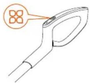
text_image
Diagram of a tool or device with an orange annotation box highlighting four square features.text_image
Diagram of a power switch with an orange button labeled 'Power' pointing to the switch handle.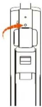
natural_image
Line drawing of a vertical cylindrical device with an orange arrow pointing to its top section (no text or symbols)natural_image
Line drawing of a mechanical device with a handle and base (no text or symbols)natural_image
Line drawing of a vacuum cleaner with an orange annotation highlighting a paint drop (no text or symbols present)クリーニングモード
SMART SMARTモード
natural_image
Line drawing showing a hand cleaning a cylindrical device with a power button (no text or symbols)汚水タンク
natural_image
Four-step diagram showing a hand operating a device with a lever, demonstrating fluid flow and mechanical assembly (no text or symbols)① ② ③ ④
ローラーブラシのセルフクリーニング
natural_image
Line drawing of a vacuum cleaner with a warning icon and mounting base (no text or symbols)フィルター
natural_image
Three-step diagram showing a device being opened, then closed, and finally assembled with orange arrows indicating motion (no text or symbols)① ② ③
ローラーブラシトップカバー
natural_image
Three-step line drawings of a vacuum cleaner's internal components, showing hand positioning, cleaning, and cleaning steps (no text or symbols)故障处理