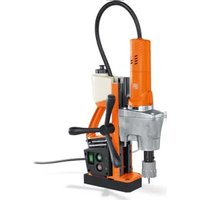
KBE 50-2 - Drill Fein - Free user manual and instructions
Find the device manual for free KBE 50-2 Fein in PDF.

 FR
FR
 BG
BG
 CS
CS
 DA
DA
 DE
DE
 EL
EL
 EN
EN
 ES
ES
 ET
ET
 FI
FI
 HU
HU
 IT
IT
 JA
JA
 KO
KO
 LT
LT
 LV
LV
 NL
NL
 NO
NO
 PL
PL
 PT
PT
 RO
RO
 RU
RU
 SK
SK
 SL
SL
 SV
SV
 TH
TH
 TR
TR
 UK
UK
 ZH
ZH
| Brand | Fein |
| Model | KBE 50-2 |
| Product type | Magnetic drill press |
| Power input (P1) | Not specified in the manual |
| Useful power (P2) | Not specified in the manual |
| No-load speed (n0) | Not specified in the manual |
| Max. chuck capacity | Not specified in the manual |
| Drilling diameter steel - carbide cutter | Not specified in the manual |
| Drilling diameter steel - twist drill | Not specified in the manual |
| Weight according to EPTA-Procedure 01 | Not specified in the manual |
| Permissible ambient temperature | Not specified in the manual |
| Sound pressure level LpA | Not specified in the manual |
| Sound power level LwA | Not specified in the manual |
| Power supply type | Electric, 230 V (check the rating plate) |
| Main functions | Drilling of magnetic materials with core cutters and twist drills |
| Safety device | Thermal protection, automatic restart after power cut, safety switch |
| Fixing method | Electromagnetic base, safety strap supplied |
| Maintenance and cleaning | Blow out ventilation slots with compressed air, inspect hoses and lines |
| Spare parts and repairability | Cutting tools, lubricant tank replaceable by user; other parts by FEIN after-sales service |
| General information | Operating manual and general safety instructions included; legal warranty and declaration of conformity |
Frequently Asked Questions - KBE 50-2 Fein
User questions about KBE 50-2 Fein
0 question about this device. Answer the ones you know or ask your own.
Ask a new question about this device
Download the instructions for your Drill in PDF format for free! Find your manual KBE 50-2 - Fein and take your electronic device back in hand. On this page are published all the documents necessary for the use of your device. KBE 50-2 by Fein.
USER MANUAL KBE 50-2 Fein
OBJ_BUCH-000000296-001.book Page 1 Wednesday, February 7, 2018 3:03 PM

▶ KBE 35 (**) 7 270 .. ▶ KBE 50-2 (**) 7 270 .. ▶ KBE 50-2M (**) 7 270 .. ▶ KBE 65-2M (**) 7 270 ..


EN 61029-1:2009 + Cor.:2009 + A11:2010 EN 55014-1:2006 + A1:2009 + A2:2011 EN 55014-2:2015 EN 61000-3-2:2014 EN 61000-3-3:2013 2011/65/EU, 2006/42/EG, 2014/30/EU

Dunih
I. V. A. Gansen
Director of Product
Development
I. V. Dr. Schreiber
Head of Development/
Electronics and Drives
a. C. 2 E. H. GCH. Pival in China. Although an average total of the average duration is below 3 h. 01:267, 06:0 BY 2018.02 DE

natural_image
Four industrial drill press machines in different configurations, shown from different angles (no text or labels visible)2
| KBE35 (**) | KBE50-2 (**) | KBE50-2M (**) | KBE65-2M (**) | |
| 7 270 .. 7 270 .. 7 270 .. 7 270 .. | ||||
| P_1 | W 850 1100 1100 1200 | |||
| P_2 | W 450 650 650 700 | |||
| n_OR | ||||
| ● | /min, min ^-1 , rpm,r/min 620 330 330 310 | |||
| ●● | /min, min ^-1 , rpm,r/min | -650 650 630 | ||
| kg 11,8 12,5 13,5 13,8 | ||||
| Fe HM | mm 12 - 35 12 - 50 12 - 50 12 - 65 | |||
| Fe HSS | mm 12 -35 12 -50 12 -50 12 - 50 | |||
| Fe HSS | mm 13 16 23 25 | |||
| L_pA | dB 87,5 88,5 88,5 88,5 | |||
| K_pA | dB | 3 | 3 | 3 |
| L_wA | dB 98,5 99,5 99,5 99,5 | |||
| K_wA | dB | 3 | 3 | 3 |
| L_pCpeak | dB | 102,3 | 102,5 | 102,5 |
| K_pCpeak | dB | 3 | 3 | 3 |
| _h | m/s ^2 | <2,5 | <2,5 | <2,5 |
| K_a | m/s ^2 | 1,5 | 1,5 | 1,5 |
| T_a | °C | -0 ... + 45 | -0 ... + 45 | -0 ... + 45 |
3
| de | 20 | pt | 44 | tr | 69 | sl | 93 | et | 119 | th | 144 |
| en | 24 | el | 48 | hu | 73 | sr | 97 | lt | 123 | ja | 149 |
| fr | 28 | da | 53 | cs | 77 | hr | 101 | lv | 127 | hi | 153 |
| it | 32 | no | 57 | sk | 81 | ru | 105 | zh(CM) | 131 | ar | 160 |
| nl | 36 | sv | 61 | pl | 85 | uk | 110 | zh(CK) | 136 | ||
| es | 40 | fi | 65 | ro | 89 | bg | 114 | ko | 140 |




OBJ BUCH-0000000296-001.book Page 4 Wednesday, February 7, 2018 3:47 PM


4







OBJ BUCH-0000000296-001.book Page 5 Wednesday, February 7, 2018 3:47 PM


5
flowchart
graph TD
    A["Feed Pump"] --> B["1. Upper pipe with inlet"]
    B --> C["2. Top pipe with outlet"]
    C --> D["3. Lower pipe with inlet"]
    D --> E["4. Lower pipe with outlet"]
    E --> F["5. Condenser unit with inlet and outlet"]




6



8





OBJ BUCH-0000000296-001.book Page 9 Wednesday, February 7, 2018 3:47 PM


9




10





OBJ BUCH-0000000296-001.book Page 11 Wednesday, February 7, 2018 3:47 PM


11




12
flowchart
graph TD
    A["Start"] --> B{KBE 50-2 (**)}
    B --> C["KBE 50-2M (**)"]
    B --> D["KBE 65-2M (**)"]
    C --> E["Route to Bike"]
    D --> E
    E --> F["Loop Back to Bicycle"]
    F --> G["● = Bicycle"]
    F --> H["● = Bicycle"]
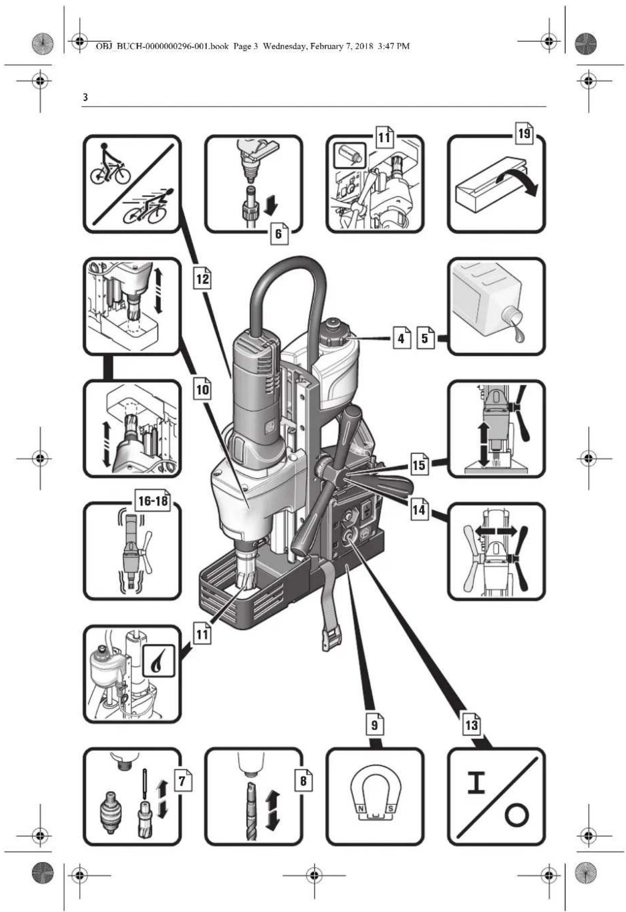
| IE ∘ Fe HM | Fe HSS | ||||
| KBE 35 (**) | ● | 12 35 mm | 1,5 +3 mm | ||
| KBE 50-2 (** )KBE 50-2M (**) | ● | 27 50 mm | 16 23 mm | ||
| KBE 65-2M (**) | ● | 27 65 mm | 16 25 mm | ||
| KBE 50-2 (** )KBE 50-2M (**)KBE 65-2M (**) | ●● | 12 26 mm | 1,5-15 mm | ||









OBJ BUCH-0000000296-001.book Page 14 Wednesday, February 7, 2018 3:47 PM


14


OBJ BUCH-0000000296-001.book Page 15 Wednesday, February 7, 2018 3:47 PM


15





OBJ BUCH-0000000296-001.book Page 17 Wednesday, February 7, 2018 3:47 PM


17




18
de
Original Instructions.
Symbols, abbreviations and terms used.
| Symbol, character Explanation | |
 | Make sure to read the enclosed documents such as the Instruction Manual and the General Safety Instructions. |
 | Observe the instructions in the text or graphic opposite! |
 | Observe the instructions in the text or graphic opposite! |
 | Before commencing this work step, pull the mains plug out of the socket. Otherwise there will be danger of injury if the power tool should start unintentionally. |
 | Use eye protection during operation. |
 | Use ear protection during operation. |
 | Do not touch the rotating parts of the power tool. |
 | Warning against sharp edges of application tools, such as the cutting edges of the cutter blades. |
 | Danger of slipping! |
 | Caution! Falling objects! |
 | Hot surface! |
 | Do not reach in! |
| [2233] | General prohibition sign. This action is prohibited. |
 | Confirms the conformity of the power tool with the directives of the European Community. |
| WARNING | This sign indicates a possible dangerous situation that could cause severe or fatal injury. |
 | Worn out power tools and other electrotechnical and electrical products should be sorted separately for environmental-friendly recycling. |
 | 1st gear/2nd gear |
| [400] | Steel |
| [44A6] | Low speed |
| [YCXX] | High speed |
| [3XT2] | Magnetic holding power, sufficient |
 | Magnetic holding power, insufficient |
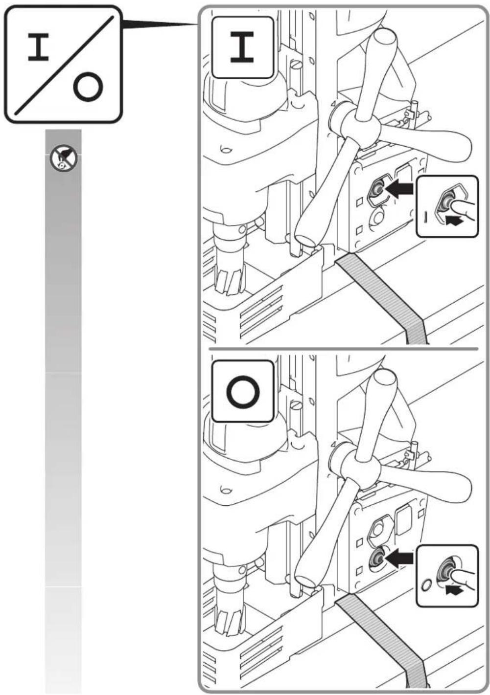
 | Starts the drill motor. Rotation direction: clockwise |
WARNING
| Symbol, character Explanation | |
| Stops the motor | |
| (**) may contain numbers and letters | |
| Character Unit of measure-ment, international | Unit of measurement, national | Explanation | |
| P_1 | W | W | P o w |
| P_2 | W | W | O u t |
| n_OR | /min, min ^-1 , rpm, r/min | rpm No-load speed | (clockwise) |
| in | inch inch Size | ||
| UV | V | R | a t e |
| f/Hz Hz Frequency | |||
| M... | mm | mm Size of metric thread | |
| ∅ | mm | mm Diameter of a round part | |
| IE O Fe HM | mm | mm Drilling capacity in steel - TCT (core drill bit) | |
| IE O Fe HSS | mm | mm Drilling capacity in steel - high speed steel (HSS) (core drill bit) | |
| IN O Fe HSS | mm | mm Drilling capacity in steel - high speed steel (HSS) (twist drill bit) | |
| mm | mm Max. drill chuck capacity | ||
| kg | kg | Weight according to EPTA-Procedure 01 | |
| T_a | °C | °C | Allowable ambient temperature |
| L_pA | dB | dB | Sound pressure level |
| L_wA | dB | dB | Sound power level |
| L_pCpeak | dB | dB | Peak sound pressure level |
| K... | Uncertainty | ||
| m, s, kg, A, mm, V, W, Hz, N, °C, dB, min, m/s ^2 | m, s, kg, A, mm, V, W, Hz, N, °C, dB, min, m/s ^2 | Basic and derived units of measurement from the international system of units SI. | |
e
P
d
For your safety.
WARNING
Read all safety warnings and all instructions. Failure to follow the
warnings and instructions may result in electric shock, fire and/or serious injury.
Save all warnings and instructions for future reference.

Do not use this power tool before you have thoroughly read and completely understood this Instruction Manual and the enclosed "General
Safety Instructions" (document number
3 41 30 054 06 1). The documents mentioned should be kept for later use and enclosed with the power tool, should it be passed on or sold.
Please also observe the relevant national industrial safety regulations.
Intended use of the power tool:
Magnetic core drill unit for drilling with core drill bits and solid drill bits on materials with surfaces suitable for magnets in weather-protected environments using the application tools and accessories recommended by FEIN.
This power tool is also suitable for use with AC generators with sufficient power output that correspond to the Standard ISO 8528, design type G2. This Standard is particularly not complied with when the so-called distortion factor exceeds 10% .When in doubt, please refer to the generator instruction/specification guide.
These appliances are not intended for use by persons (including children) with reduced physical, sensory or mental capabilities, or lack of experience and knowledge, unless they have been given supervision or instruction concerning use of the appliance by a person responsible for their safety.
Children should be supervised to ensure that they do not play with the appliance.
Special safety instructions.
Wear personal protective equipment. Depending on application, use face shield, safety goggles or safety glasses. Where appropriate, wear dust mask, hearing protectors, gloves and workshop apron capable of stopping small abrasive or workpiece fragments. The eye protection
en
must be capable of stopping flying debris generated by various operations. The dust mask or respirator must be capable of filtrating particles generated by your operation. Prolonged exposure to high intensity noise may cause hearing loss.
Do not touch the sharp edges of the core drill bit. Danger of Injury.
Before putting into operation: Mount the contact protector to the machine.
Replace the protective cable bushing immediately when damaged. A defective protective cable bushing can lead to overheating of the machine and to an emergency stop.
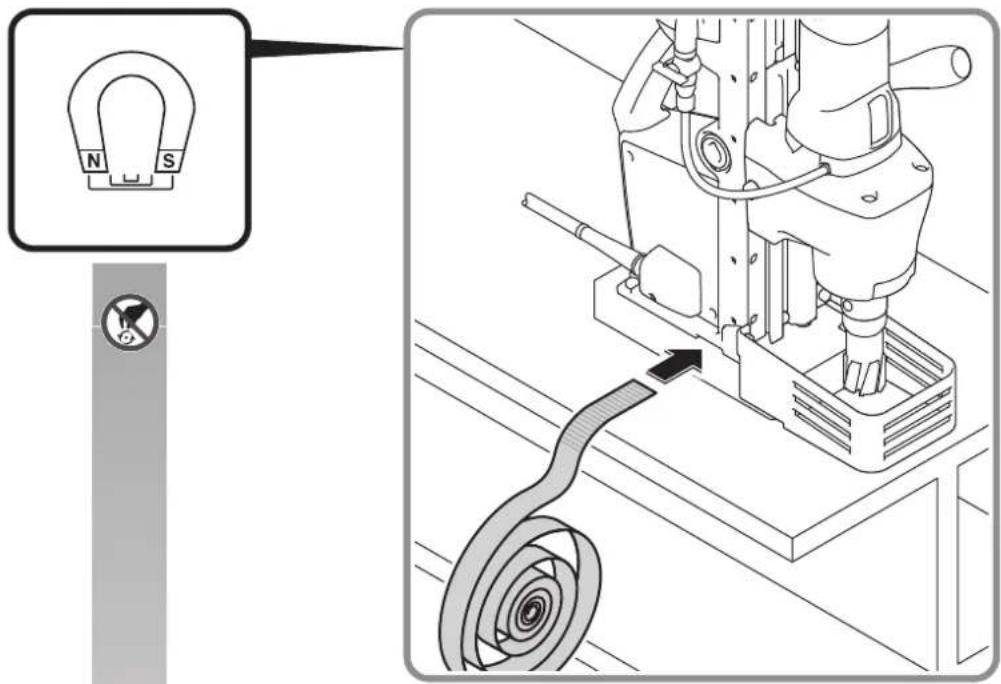
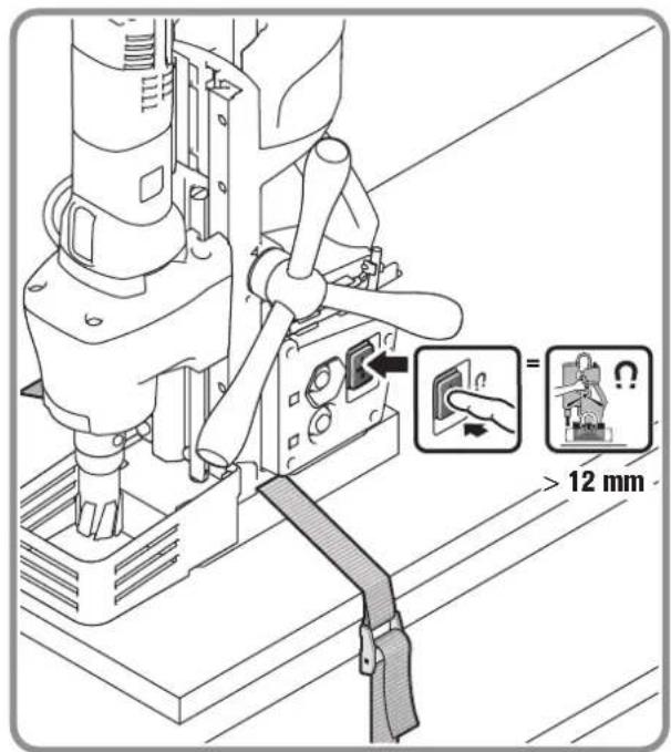
Always secure the power tool with with the supplied lashing strap. In case of a power failure or when the mains plug is pulled, the magnetic holding power is not maintained. When carrying out such work, beware of falling objects, such as cores or chips.
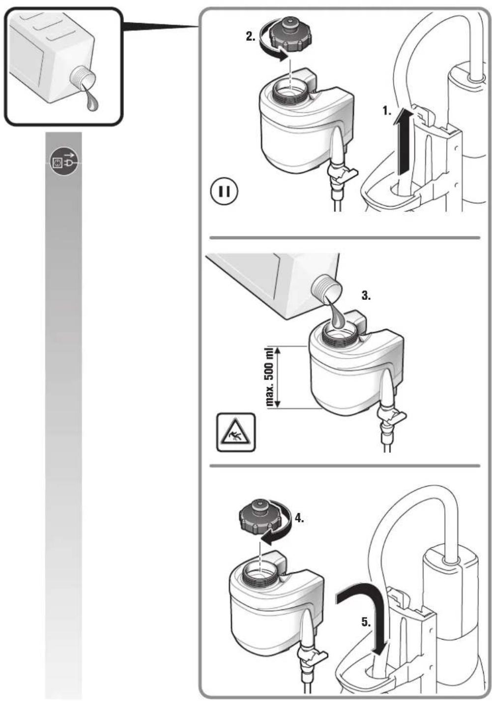
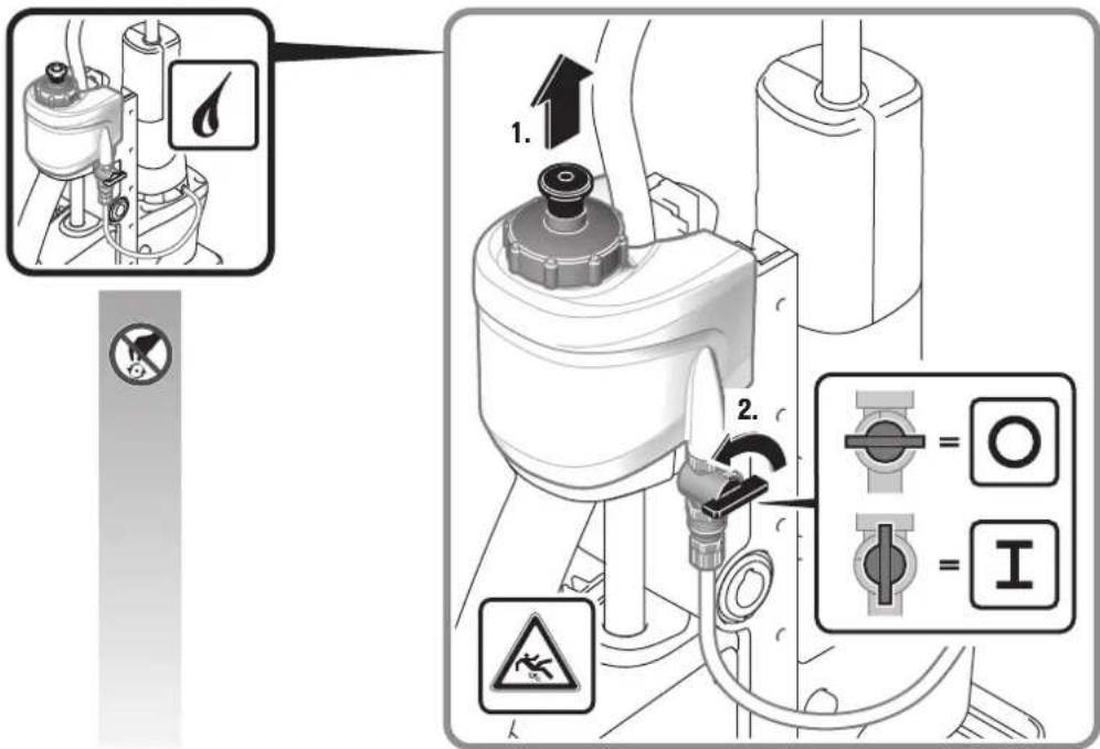
When working overhead or on vertical surfaces, the coolant container must not be used. Use a coolant spray instead. Liquids penetrating your electric power tool may cause electric shock.
Avoid touching the drilled core that is automatically ejected by the centering pin when the working procedure is finished. Contact with the core when it is hot, or if it falls, can cause personal injuries.
Operate the power tool only from grounded sockets that comply with the specifications. Do not use any connection cables that are damaged; use extension cables with a grounding contact that are checked at regular intervals. A ground conductor without continuity can cause an electric shock.
To prevent injuries, always keep your hands, clothing, etc. away from rotating swarf. The swarf can cause injuries.
Do not attempt to remove the cutting tool if it still turns. This can lead to serious injuries.
Hold power tool by the insulated gripping surfaces, when performing an operation where the cutting accessory may contact hidden wiring or its own cord. Cutting accessory contacting a "live" wire may make exposed metal parts of the power tool "live" and could give the operator an electric shock.
Beware of any concealed electric cables, gas or water conduits. Check the working area before commencing work, e.g. with a metal detector.
Do not work materials containing magnesium. Danger of fire.
Do not work CFP (carbon-fiber-reinforced polymer) and materials containing asbestos. These materials are considered carcinogenic.
Do not rivet or screw any name-plates or signs onto the power tool. If the insulation is damaged, protection against an electric shock will be ineffective. Adhesive labels are recommended.
Do not overload the power tool or the storage case and do not use it as a ladder or stand. Overloading or standing on the power tool or the storage case can lead to the upward shifting of the centre of gravity of the power tool or the storage case, and its tipping over.
Do not use accessories which are not specifically designed and recommended by the power tool manufacturer. Safe operation is not ensured merely because an accessory fits your power tool.
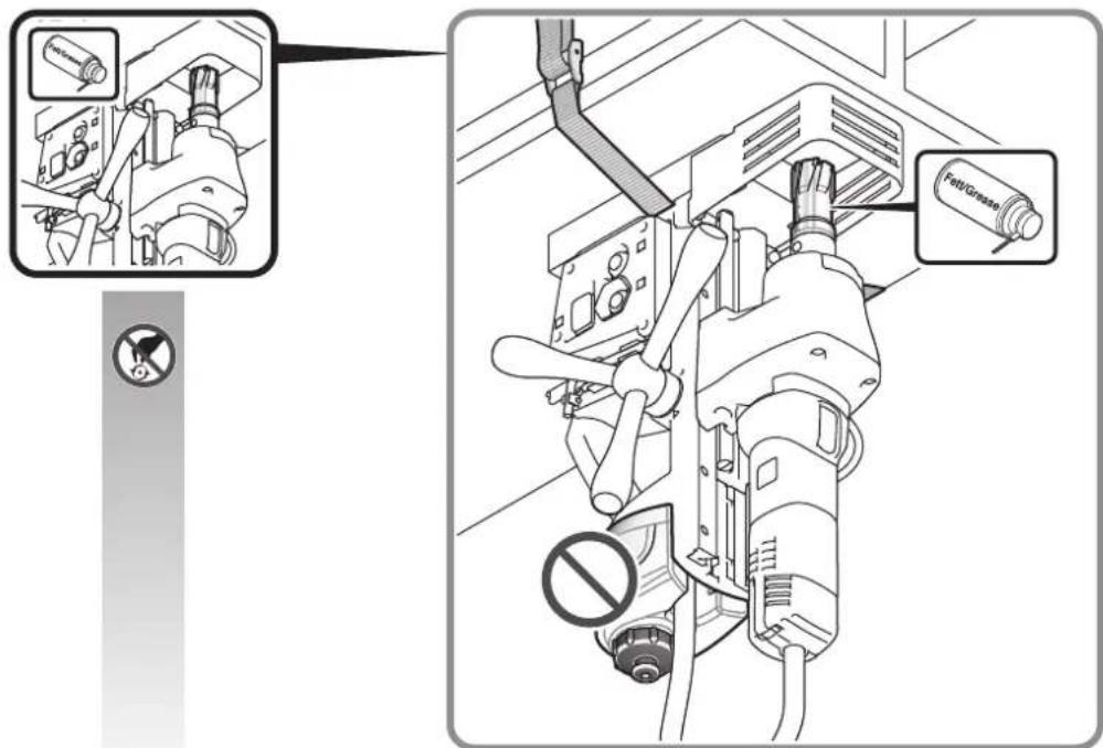
Clean the ventilation openings on the power tool at regular intervals using non-metal tools. The blower of the motor draws dust into the housing. An excessive accumulation of metallic dust can cause an electrical hazard.
Before putting into operation, check the mains connection and the mains plug for damage.
Recommendation: The tool should always be supplied with power via a residual current device (RCD) with a rated current of 30 mA or less.
Hand/arm vibrations
The vibration emission level given in this information sheet has been measured in accordance with a standardised test given in EN 60745 and may be used to compare one tool with another. It may be used for a preliminary assessment of exposure.
The declared vibration emission level represents the main applications of the tool. However, if the tool is used for different applications, with different accessories or poorly maintained, the vibration emission may differ. This may significantly increase the exposure level over the total working period.
An estimation of the level of exposure to vibration should also take into account the times when the tool is switched off or when it is running but not actually doing the job. This may significantly reduce the exposure level over the total working period.
Identify additional safety measures to protect the operator from the effects of vibration such as: maintain the tool and the accessories, keep the hands warm, organisation of work patterns.
Operating Instructions.
Only use water-soluble cutting fluids [oil in water] as the cooling agent.
Observe the manufacturer's instructions on coolant. Please make sure that the contacting surface for the magnetic base is level, clean and rust-free. Remove any varnish or primer.
Pay attention that the magnetic holding power is sufficient.
When working on materials that are not magnetizable, suitable fixation devices, obtainable as accessories from FEIN, e. g. suction plate, vacuum plate or pipe-drilling device must be used.
When working on steel materials with a material thickness of less than 12 mm, the workpiece must be reinforced with an additional steel plate in order to guarantee the magnetic holding power.
Work only with the absolutely required amount of feed. Excessive feed can lead to breakage of the application tool and loss of the magnetic holding power.
When the power supply is disconnected while the motor is running, a protective circuit prevents automatic restarting of the motor. Restart the motor again.
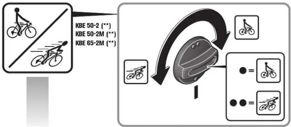
Adjust the gear setting only when the machine is at a complete stop or when the motor is running down.
Do not stop the drill motor during the drilling procedure.




Only remove the core bit from the drilled hole while the motor is running.
If the core bit should remain stuck in the material, stop the drill motor and carefully turn the core bit out counter-clockwise.
Remove the chips and the drilled core after each drilling process.
Do not touch the chips with your bare hand. Always use a chip hook.
Danger of burning! The surface of the magnet can reach high temperatures. Do not touch the magnet with your bare hands.
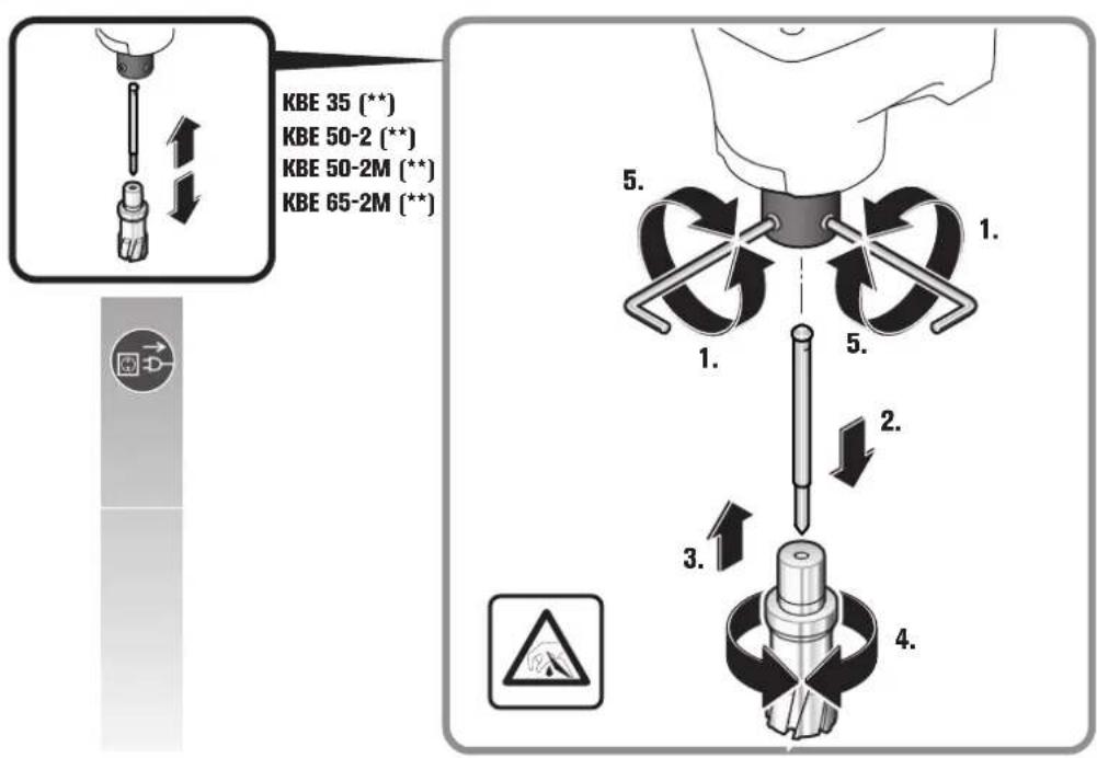
When changing a drill bit, pay attention not to damage the cutting edges.
When core drilling layered material, remove the core and the chippings after drilling each layer.
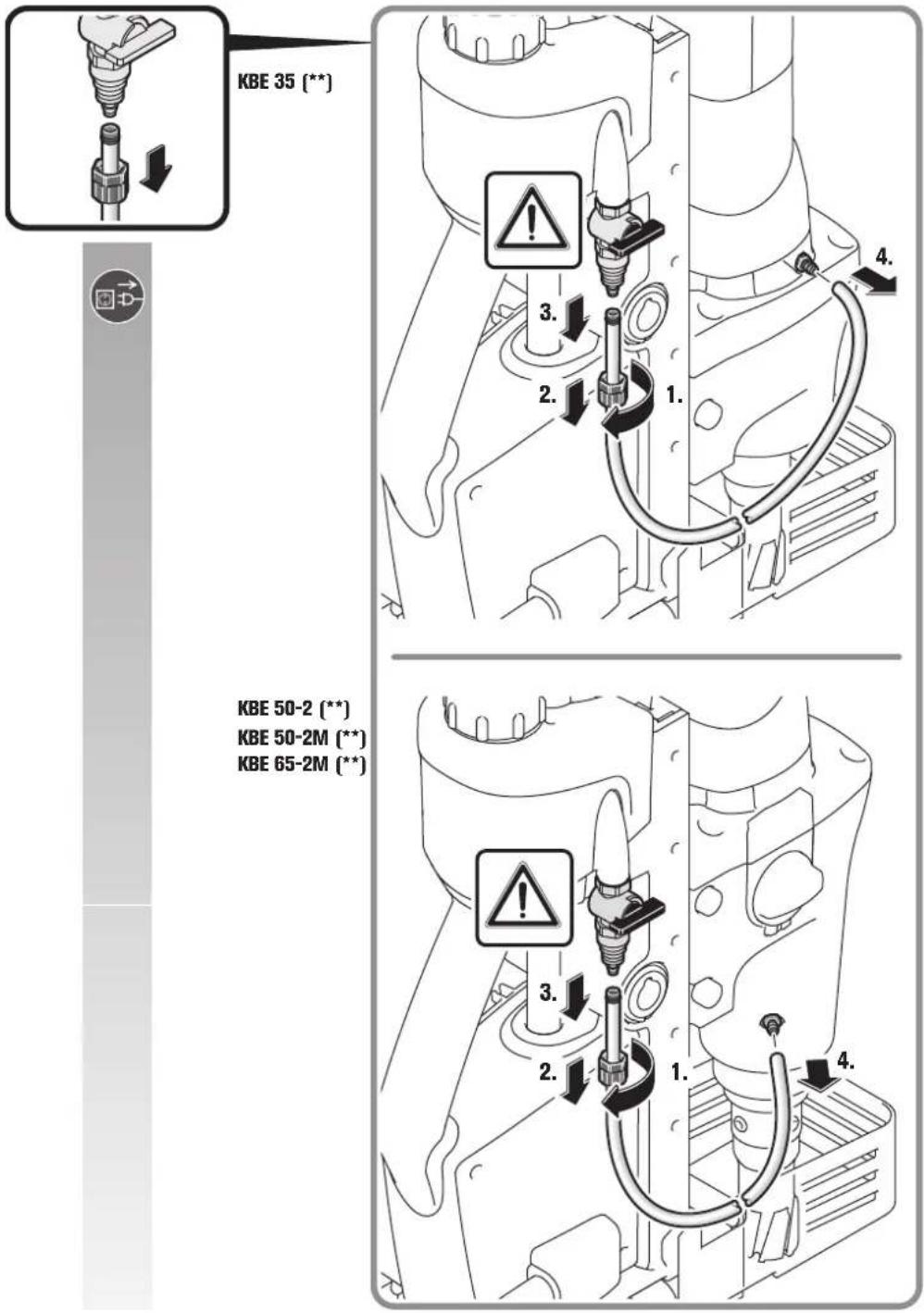
Do not use the magnetic core drill unit when the cooling-lubricant system is defective. Each time before operating, check for tightness against leaks and for cracks in the hoses. Prevent liquids from entering or penetrating electrical components.
The magnetic core drill unit is equipped with a temperature switch. When the motor gets too warm, the magnetic core drill unit switches off.
When the motor has cooled down, the magnetic core drill unit can be switched on again.
To reduce the cool-down period, the motor can be switched on by pressing and holding the ON button. During the cool-down period, the motor will only run while the ON button is pressed.
Repair and customer service.


When working metal under extreme operating conditions, it is possible for conductive dust to settle in the interior of the power tool.
The total insulation of the power tool can be impaired. Blow out the interior of the power tool via the ventilation slots frequently with dry and oil-free compressed air, and connect a residual current device (RCD) on the line side.
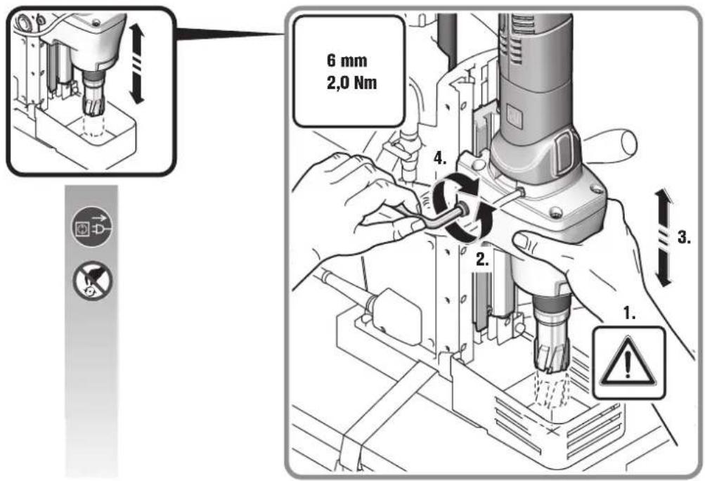
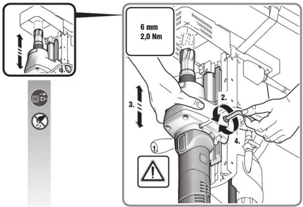
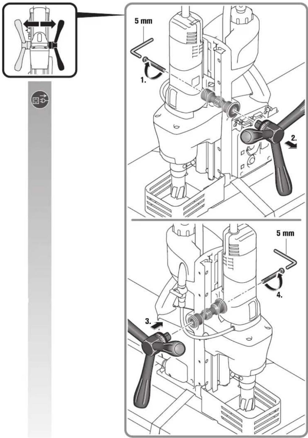
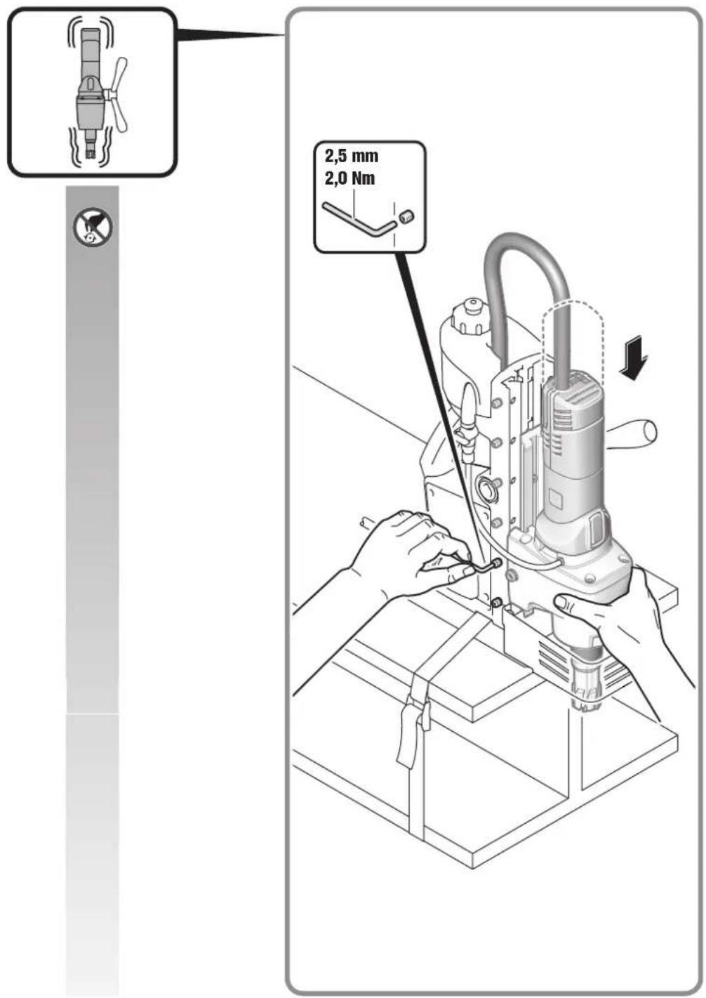
After several hours of operation, the play in the dove-tail guide can increase. As a consequence, the drill motor can glide alongside the dove-tail guide by itself. In automatic machine operation, this can lead to a malfunction of the automatic reversing feature. In this case, retighten all set screws of the dove-tail guide correspondingly so that the drill motor can easily be moved manually, yet does not glide by itself (see page 16).
If the supply cord of this power tool is damaged, it must be replaced by a specially prepared cord available through the FEIN customer service centre.
TThe current spares parts list for this power tool can be found on our website at www.fein.com.
If required, you can change the following parts yourself: Application tools, cooling-lubricant tank
Warranty and liability.
The warranty for the product is valid in accordance with the legal regulations in the country where it is marketed. In addition, FEIN also provides a guarantee in accordance with the FEIN manufacturer's warranty declaration.
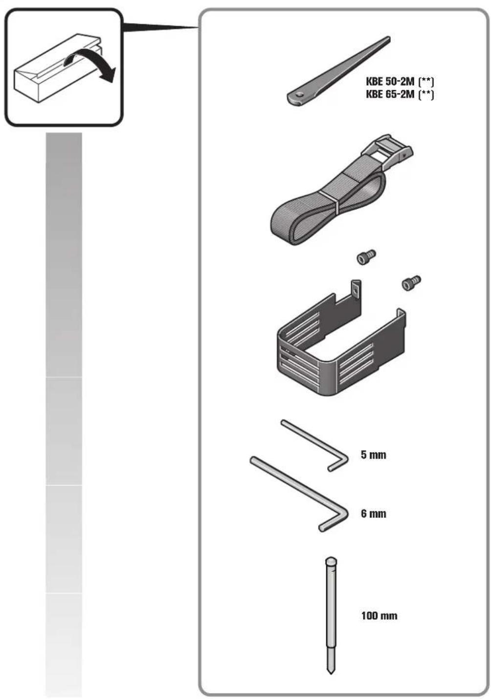
The delivery scope of your power tool may include only a part of the accessories described or shown in this Instruction Manual.
Declaration of conformity.
FEIN declares itself solely responsible for this product conforming with the relevant provisions given on the last page of this Instruction Manual.
Technical documents at: C. & E. Fein GmbH, C-DB_IA, D-73529 Schwäbisch Gmünd
Environmental protection, disposal.
Packaging, worn out power tools and accessories should be sorted for environmental-friendly recycling.




natural_image
Pure geometric diagram with crosshair and circular shapes, no text or symbols presentit
Miljøvern, deponering.
China RoHS Status Certificate
中国 RoHS 认证概况
Table of Toxic and Hazardous Substances/Elements and their Content
as required by China's Management Methods for Controlling Pollution by Electronic Information Products
有毒有害物质 / 成分及其含量表


- de
- WARNING
- For your safety.
- Intended use of the power tool:
- Special safety instructions.
- en
- Hand/arm vibrations
- Operating Instructions.
- Repair and customer service.
- Warranty and liability.
- Declaration of conformity.
- Environmental protection, disposal.
- it
- Miljøvern, deponering.
- China RoHS Status Certificate
- 中国 RoHS 认证概况
Brand : Fein
Model : KBE 50-2
Category : Drill