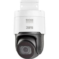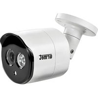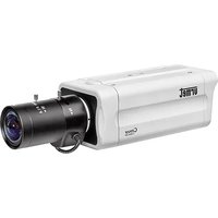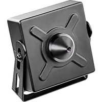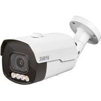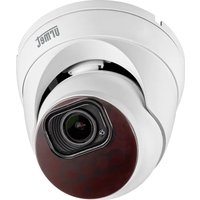
VK 1099/461A - Surveillance Camera GROTHE - Free user manual and instructions
Find the device manual for free VK 1099/461A GROTHE in PDF.


| Product type | IP surveillance camera |
| Brand | Grothe |
| Model | VK 1099/461A |
| Power supply | Included power adapter (12V DC) or PoE (depending on model) |
| Video resolution | HD 1080p (1920x1080) |
| Night vision | Yes, integrated infrared |
| Field of view | Not specified in manual, variable depending on lens |
| Local storage | SD card (not included, up to 128 GB recommended) |
| Connectivity | Ethernet RJ45 (10/100 Mbps) |
| Motion detection | Yes, with sensitivity adjustment and actions (recording, email) |
| Sound detection | Yes (depending on model, can be activated via audio alarm) |
| PIR detection | Yes (depending on model 1099/208, passive infrared motion detector) |
| Deterrent function | Yes (depending on model, siren and strobe light) |
| Smartphone app | Urmet iUVS plus (iOS and Android) |
| Network configuration | DHCP by default, static IP possible (192.168.1.168) |
| Installation | Ceiling or wall mount (mounting kit included) |
| Operating temperature | -10°C to +50°C (estimate) |
| Protection rating | Not specified, indoor use recommended |
| Dimensions (approx.) | Diameter 100 mm, height 80 mm (estimate for bullet model) |
| Weight (approx.) | 300 g (estimate) |
| Maintenance and cleaning | Soft dry cloth, disconnect before cleaning |
| Safety | Do not expose to moisture, do not open, use by qualified personnel |
| General information | Full manual and software available at www.urmet.com |
Frequently Asked Questions - VK 1099/461A GROTHE
User questions about VK 1099/461A GROTHE
0 question about this device. Answer the ones you know or ask your own.
Ask a new question about this device
Download the instructions for your Surveillance Camera in PDF format for free! Find your manual VK 1099/461A - GROTHE and take your electronic device back in hand. On this page are published all the documents necessary for the use of your device. VK 1099/461A by GROTHE.
USER MANUAL VK 1099/461A GROTHE
natural_image
White surveillance camera icon on light blue background (no text or symbols)IT | EN | DE | FR
www.urmet.com
Quick guide
H.265 IP CAMERA SERIES
INDICE
INDICE....2
text_image
Slot SD card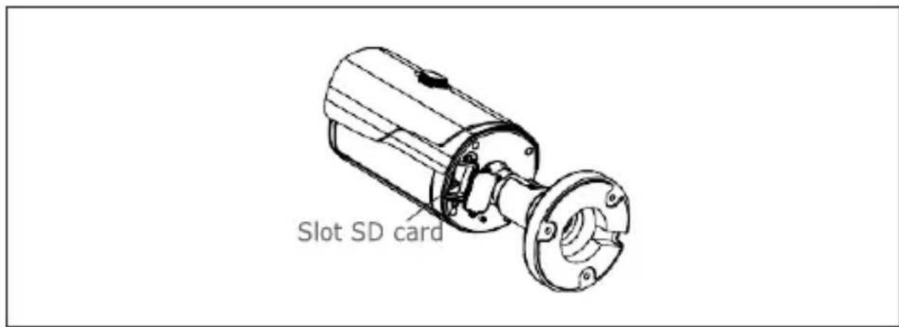
text_image
Slot SD cardnatural_image
Close-up of a black mechanical component with yellow directional arrows indicating features (no text or symbols)natural_image
Interior view of an open electronic device showing a green circuit board with wires and connectors, no visible text or symbols.natural_image
Diagram of a mechanical component with a wheel and textured surface (no text or symbols)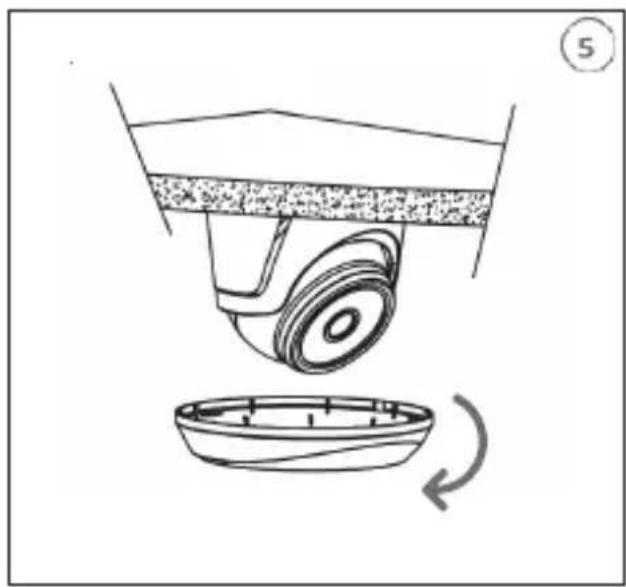
natural_image
Diagram of a mechanical device with a rotating base and a curved component, no text or symbols present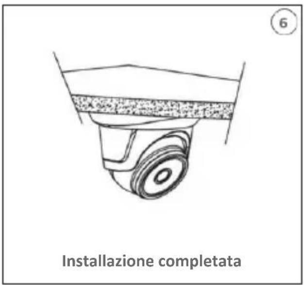
natural_image
Exploded view diagram of a mechanical assembly showing internal components (no text or labels)text_image
4 Calottanatural_image
Close-up of a mechanical component with a yellow arrow pointing to a small component (no visible text or symbols)natural_image
Technical line drawing of a mechanical clutch assembly (no text or symbols)Slot SD card
text_image
User Info Username admin Password ***** Device Info Start IP Media Port Web Port Gateway Net Mask Net Mode Static Modifytext_image
You haven't installed the plugin or it is not the latest version. Please click download to download the latest plugin. Please close browser before plugin installation!!! Exhibit: Web plugin (1.6) UK 45/1981.122? Exhibit: Save Analyzetext_image
Setup - WebPlugin Ready to Install Setup is now ready to begin installing WebPlugin on your computer. Click Install to continue with the installation. Install Canceltext_image
urmet Live Playback FX driving Setting Local Settings F20 Setting F20 Open DOOM FOCUS Audio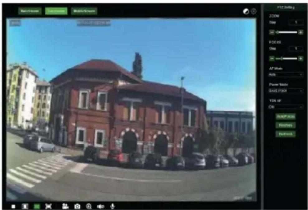
text_image
Main of the Main of the Mobile Stream 0000 0000 0000 0000 0000 0000 0000 0000 0000 0000 0000 0000 0000 0000 0000 0000 0000 0000 0000 0000 0001 0011 0123 1234 1235 1236 1237 1238 1239 1240 1241 1242 1243 1244 1245 1246 1247 1248 1249 1250 1251 1252 1253 1254 1255 1256 1257 1258 1259 1260 1261 1262 1263 1264 1265 1266 1267 1268 1269 1270 1271 1272 1273 1274 1275 1276 1277 1278 1279 1280 1281 1282 1283 1284 1285 1286 1287 1288 1289 1290 1291 1292 1293 1294 1295 1296 1297 1298 1299 1300 1301 1302 1303 1304 1305 1306 1307 1308 1309 1310 1311 1312 1313 1314 1315 1316 1317 1318 1319 1320 1321 1322 1323 1324 1325 1326 1327 1328 1329 1330 1331 1332 1333 1334 1335 1336 1337 1338 1339 1340 1341 1342 1343 1344 1345 1346 1347 1348 1349 1350 1351 1352 1353 1354 1355 1356 1357 1358 1359 1360 1361 1362 1363 1364 1365 1366 1367 1368 1369 1370 1371 1372 1373 1374 1375 1376 1377 1378 1379 1380
text_image
urmet Live Playbook Premise Setting Local Settings Display Record Networks Actions Name: 196 Details Sound Detection Device System Advanced Static Smoothweb Play Recording Send Event Colorset Enable Record Refresh Save OK Alttext_image
urmet Live Playback Remote Setting Losel Settings Display Record Network Avon mask my Defense Sound Detachment Device System Advanced Light Light Level 62 Duration 5 (5~100s) Color Image Light Mode Viewing Light Clear Clear Level 2 Clear Duration 4 (8~100s) Stream Web Refresh Save Cancel Update Clear Alltext_image
QR code image containing encoded data, no visible human-readable texttext_image
QR code image containing encoded data, no visible human-readable texttext_image
QR code image containing encoded data, no visible human-readable textQuick guide
H.265 IP CAMERA SERIES
INDEX
INDEX 27
General information 28
WARNINGS 28
Installation 30
INSTALLATION OF BULLET CAMERAS 30
INSTALLATION OF MINI DOME CAMERAS 33
MINI FLAT CAMERA INSTALLATION.... 34
INSTALLATION OF VANDAL-PROOF DOME CAMERAS.... 36
IP Camera Configurations 37
CONNECTION TO IP NETWORK WITH DHCP SERVICE 37
PTZ CONTROL....41
MOTION ALARM MANAGEMENT....44
PIR ALARM MANAGEMENT....44
DETERRENCE FUNCTION CHECK (only for model 1099/208) 45
SOUND ALARM MANAGEMENT 46
Mobile software 46
SMARTPHONE DEVICE 46
General information
Dear Customer,
Thank you for purchasing this product.
This quick start guide was written to help you set up H.265 IP Camera Series rapidly and easily.
Read this quick start guide which contains information for correct, safe use carefully before using the device.
Keep this guide at hand so that you can refer to it when needed.
\*NOTE
For more detailed information about the devices, refer to the complete user manual available on the Urmet website (see QR code printed on the Addendum sheet).
WARNINGS
Electricity
Before connecting to electrical outlet, verify the electrical specifications of the device are suitable for the available power source.
We suggest to connect the device to electrical outlet via a switch disconnector.
In case of malfunctioning, disconnect electrical power from the general switch.
Use only the provided power supply.
Safety precautions
Do not expose the device to rain or humidity and do not insert any solid or liquid object in it to prevent the risk of fire or electrocution. In these events disconnect the device from the electrical outlet and call technical assistance to check it.
Do not open the device. Any repair must be made by qualified personnel or by calling the nearest authorized technical assistance center (www.urmet.com >> Contacts).
Keep the device away from children to prevent any, even involuntary, damaging.
Do not touch the device with wet hands as it might cause electrical shock or mechanical damages.
If the device falls down while working or if the salesbox is damaged, do not continue using it. If usage is continued under such circumstances electrical shocks might take place.
Contact the authorized retailer or installer.
Installation precautions
Do not install the camera in places with possible exposure to rain or humidity without the proper protective case.
Do not point the camera directly to sunlight or other intense sources of light, even when turned off. The subject of recording must not be against the light.
Do not point the camera against reflective objects.
Some light conditions (such as fluorescent color) can affect the recorded colors. Use
AUTO-IRIS lens when operating the camera in changing light environments.
Do not use this device on any unstable support such as lurching or sloping table to prevent the device from falling and be damaged.
If water or any other material should penetrate the camera, stop using it as it might cause fire or electrical shock and contact the authorized retailer or installer.
Do not cover the device with any cloth while using to prevent deformation of the external part and inner components heating which might provoke fire, electrical shock or mechanical damages.
Do not put magnets or magnetized objects close to the device to prevent functional anomalies.
Do not use this device in presence of smoke, steam, humidity, dust or intense vibrations. Do not use the device shortly after moving it from warm to cold environment and vice versa. After moving the device wait three hours before using it: this time is necessary for the device to adapt to the new environment (temperature, humidity, etc.).
Usage precautions
Check the device is not damaged after removing the packaging.
Check the working environment is not too humid and the temperature is within the indicated range.
Do not point the camera against sunlight to prevent sensor damages.
Device cleaning
Use a dry cloth to remove dust and dirt from the device.
If dirt cannot be removed with a dry cloth, use a humid cloth and a neutral cleanser.
Do not use spray cleanser for device cleaning. Do not use volatile liquids such as gasoline, alcohol, solvents etc. or chemical treated cloth to clean the device to prevent deformations, damages or scars on the finishing paint.
Disconnect the device from the electrical outlet before cleaning.
Video recording
This device is not designed as a burglar system but mainly to transmit and record video images. URMET S.p.A. is not in any way responsible for loss or damages of the user consequent to theft.
Before using the device, record a demo video to verify the correct functionality of this feature. URMET S.p.A. is not in any way responsible for loss of recorded data consequent to wrong setting or usage, device malfunctioning or failure.
This device is composed by electronic precision components. Do not hit the device while recording as it might affect the video.
Privacy and Copyright
The IP camera is designed for surveillance systems. Video recording is subject to the laws applicable to the Country where used. It is forbidden to record images with Copyright.
The User is responsible to check and respect all local laws and norms for video signal
recording. The manufacturer is NOT in any way liable for any usage of the product which might result not compliant to the relevant norms.
Firmware upgrade
Contact Customer Service Technical Assistance URMET S.p.a. in order to check availability of firmware upgrades.
Network configuration
Camera default setting is DHCP mode. If the network does not support dynamic addressing (DHCP), the device will automatically switch to factory IP 192.168.1.168. Use Urmet "Device Config. Tool" software provided with IP Camera CD in order to modify the IP address and other network settings to prevent any conflict with other devices on the network.
Network connections
When connecting a PC (using Software Client or Browser), any video channel on the PC will be using "unicast" connection (TCP, RTP, UDP).
The device can support up to 10 "unicast" connections so it is possible to show the video on maximum 10 remote devices (PC or smartphone) at the same time depending on the available network band.
Installation
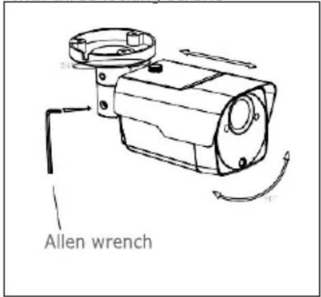
INSTALLATION OF BULLET CAMERAS
Ceiling Mounting
Insert three expansion bolts in place into the ceiling and fix the equipment with three locking screws
text_image
Allen wrench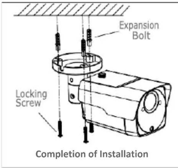
text_image
Expansion Bolt Locking Screw Completion of Installation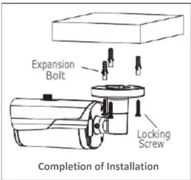
text_image
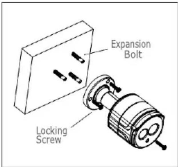
Expansion Bolt Locking Screw Completion of InstallationWall Mounting
Insert three expansion bolts in place into the wall and fix the equipment with three locking screws.
text_image
Expansion Bolt Locking Screw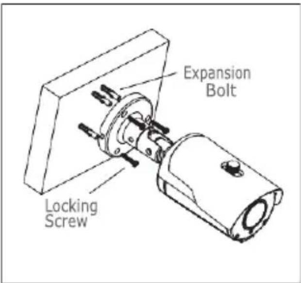
text_image
Expansion Bolt Locking Screw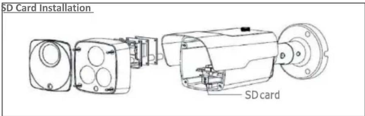
text_image
SD Card Installation SD card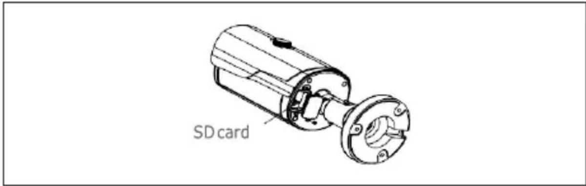
text_image
SD cardSD Card installation model 1099/208
ATTENTION: this operation must be carried out by qualified personnel.
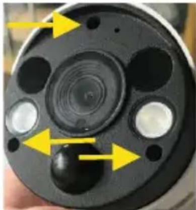
natural_image
Close-up of a black circular device with yellow directional arrows pointing to features (no text or symbols visible)Remove the 3 screws that lock the front cover
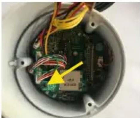
natural_image
Interior view of an electronic device showing a green circuit board, wires, and a yellow arrow pointing to a component (no visible text or symbols)- Remove the screw that secures the SD Card slot
- Insert the SD Card into the slot
- Reinsert the the SD Card slot on the motherboard
- Reinsert the screw that secures the SD Card slot
INSTALLATION OF MINI DOME CAMERAS
Ceiling Mounting
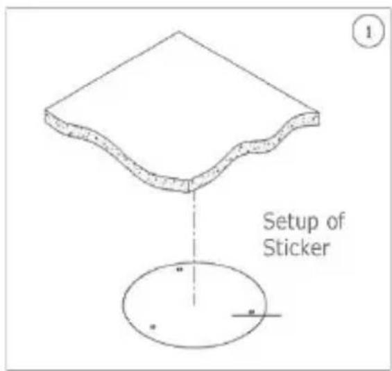
- Paste the sticker in place at the proper position as selected.
- Remove the collar off the camera by rotating it down.
- Fix the pedestal by drilling locking holes around the sticker and inserting three expansion bolts into the holes and fastening it with three locking screws.
- Adjust it to an appropriate angle.
- Mount the collar back by rotating it up.
text_image
Setup of Sticker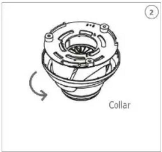
text_image
Collar ②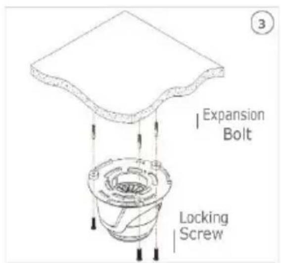
text_image
Expansion Bolt Locking Screw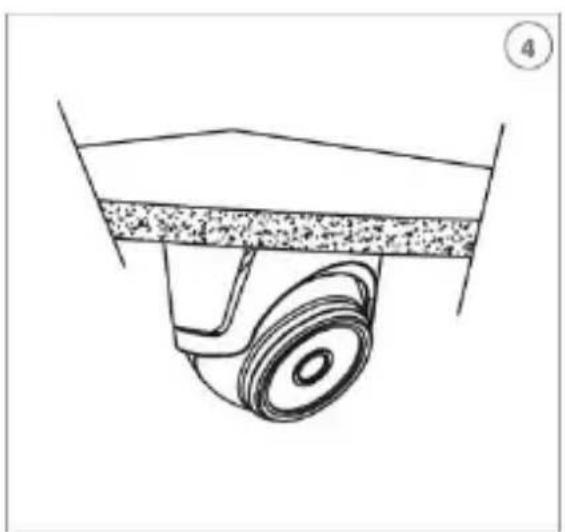
natural_image
Technical line drawing of a mechanical component with a wheel and textured surface (no text or symbols)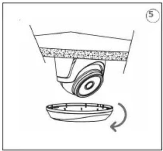
natural_image
Diagram of a mechanical device with a wheel and base, showing rotational motion (no text or symbols)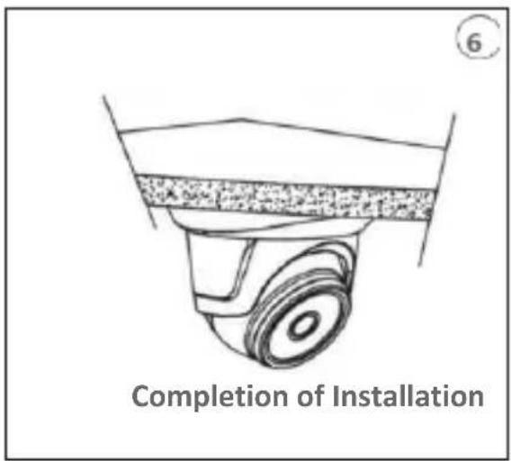
text_image
Completion of InstallationSD Card Installatio
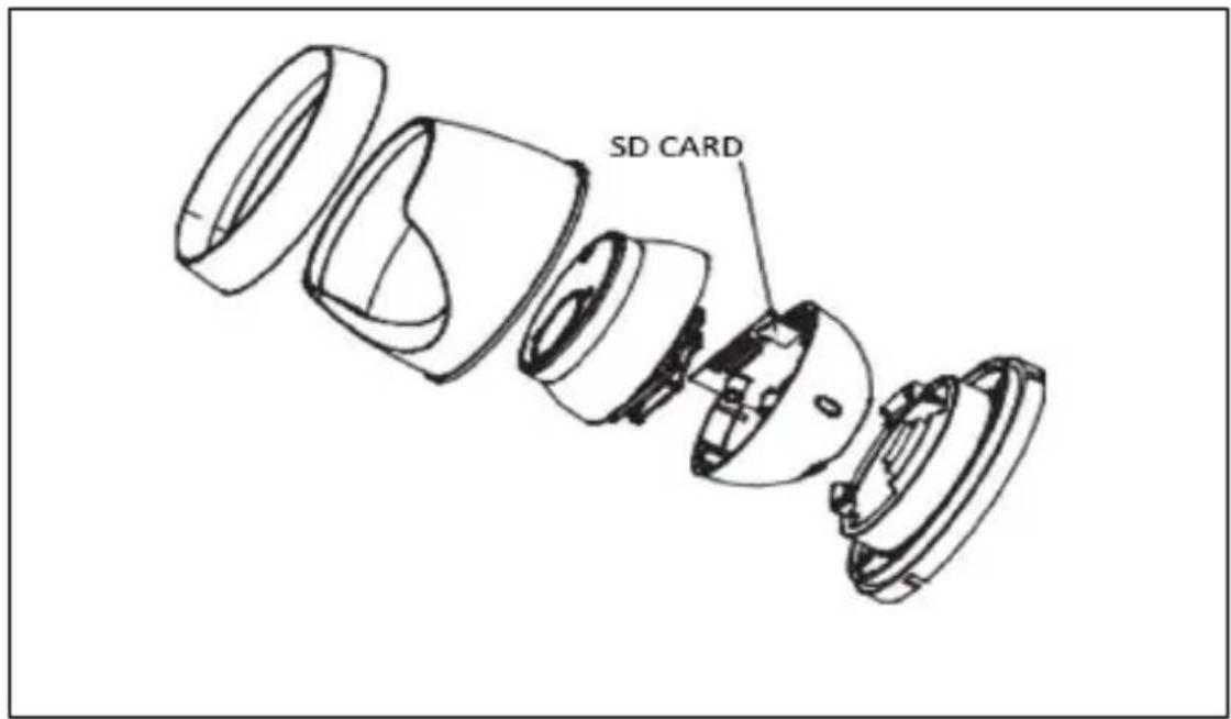
text_image
SD CARDMINI FLAT CAMERA INSTALLATION
Ceiling fixing
- Fasten the fixing bracket to the ceiling.
- Fasten the camera body to the ceiling.
- Correctly adjust the angle by rotating the camera body.
- Apply the dome cover of the camera
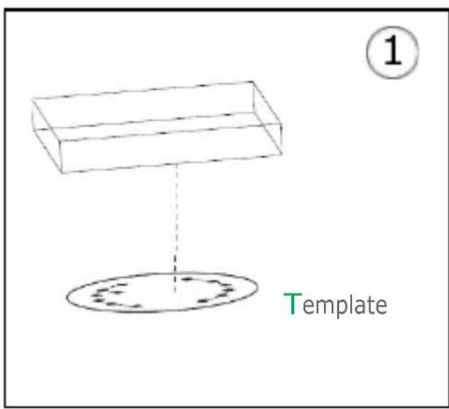
text_image
① Template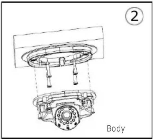
text_image
② Body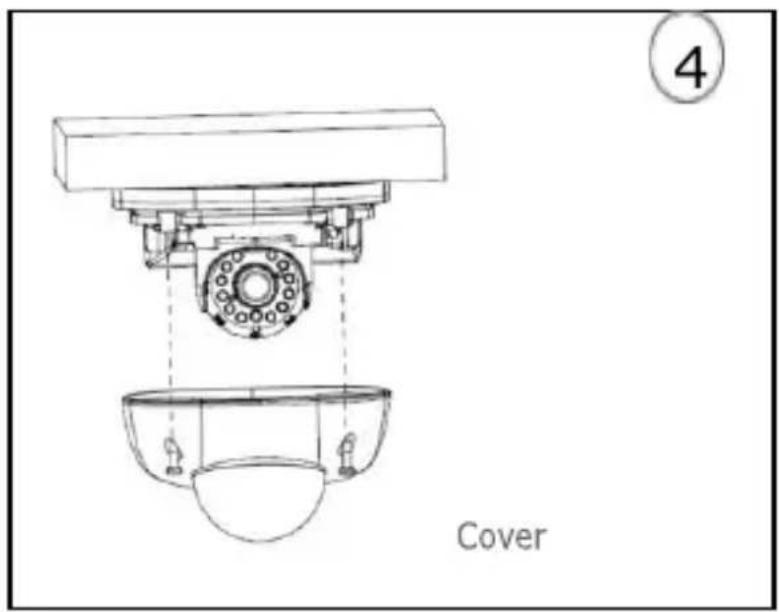
text_image
4 Covernatural_image
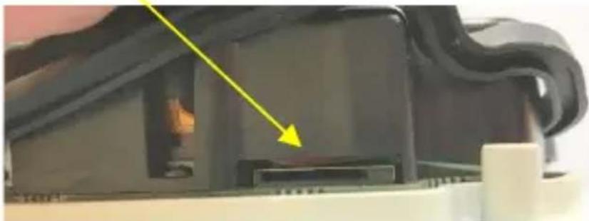
Close-up of a mechanical component with a yellow arrow pointing to a specific part (no visible text or symbols)Insert the SD Card in the slot indicated by the arrow
INSTALLATION OF VANDAL-PROOF DOME CAMERAS
Ceiling Mounting
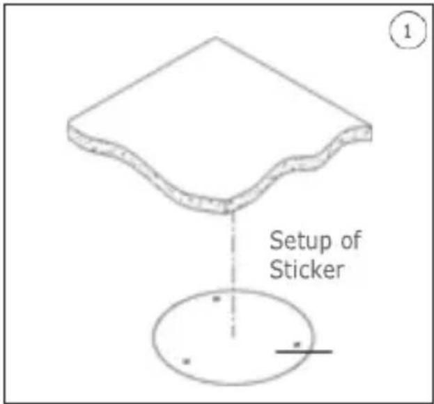
- Paste the sticker in place at the proper position as selected.
- Remove the front component by loosening the three locking screws with a screwdriver.
- Fix the pedestal by drilling locking holes around the sticker and inserting four expansion bolts into the holes and fastening it with four locking screws. Adjust it to an appropriate angle.
- x the front component on the pedestal by tightening the three locking screws.
text_image
Setup of Sticker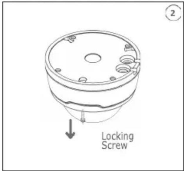
text_image
Locking Screw
text_image
Expansion Bolt Locking Screw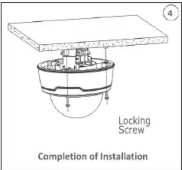
text_image
Locking Screw Completion of Installation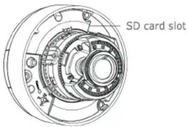
text_image
SD card slotIP Camera Configurations
The camera must be configured for the home or office network after it has been powered. It is advisable to install and configure one camera at a time if you are installing multiple cameras on the same network.
CONNECTION TO IP NETWORK WITH DHCP SERVICE
For Quick installation about IP camera with dynamic host configuration (DHCP) on the network will be assigned an IP address automatically. IF DHCP Service is not supported, the default IP Address of IP Camera will be 192.168.1.168.
IP Camera Configuration:
- Install the Software "Device Config. Tool" provided by CD and follow the installation instructions displayed at monitor.
- Launch the "Device Config. Tool" Software, selecting "Device Config Tool" it will be displayed automatically IP Address, Subnet Mask, Gateway, and MAC Address for each IP Camera detected in LAN, as shown in picture below.
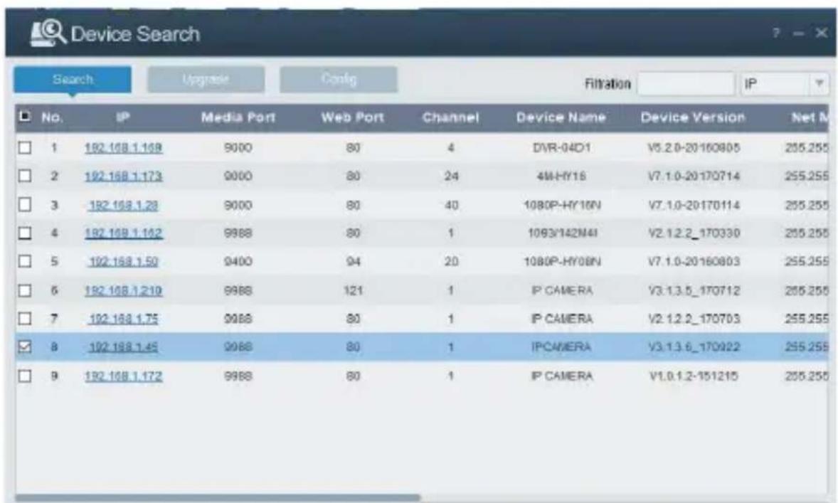
text_image
Device Search Search Upgrade Config Filtration IP No.IP Media Port Web Port Channel Device Name Device Version Net M 1 192.168.1.168 9000 80 4 DVR-04D1 V5.2.0-20160805 255.255 2 192.168.1.173 9000 80 24 4M-HY16 V7.1.0-20170714 255.255 3 192.168.1.28 9000 80 40 1080P-HY16N V7.1.0-20170114 255.255 4 192.168.1.162 9988 80 1 1093/142M4I V2.1.2.2_170330 255.255 5 192.168.1.50 9400 94 20 1080P-HY08N V7.1.0-20160803 255.255 6 192.168.1.210 9988 121 1 IP CAMERA V3.1.3.5_170712 255.255 7 192.168.1.75 9988 80 1 IP CAMERA V2.1.2.2_170703 255.255 8 192.168.1.45 9988 80 1 IPCAMERA V3.1.3.6_170922 255.255 9 192.168.1.172 9988 80 1 IP CAMERA V1.0.1.2-151215 255.255If the searched IP address and PC IP address are not in the same network segment, user may modify IP address, subnet mask, and other parameters of IP camera by using "Device Config. Tool" software.
First select the device to modify IP address and then input new IP address, subnet mask, gateway and username/password. Insert the password and click Modify "button to change IP address of the device.

text_image
User Info Username admin Password ***** Device Info Start IP Media Port Web Port Gateway Net Mask Net Mode Static Modify*IMPORTANT NOTE: IP camera Default Settings
Default Static IP Address:192.168.1.168
Username: admin
Password: admin
Media port: 9988
- Before using IE (Internet Explorer) browser to access the IP camera for the first time, related plug-in components must be installed by following the procedure below:
- Access IP address of the IP camera for installing plug-in only for the first time. In the Web Page opened select "Download", after that select "Run" in the pop-up below
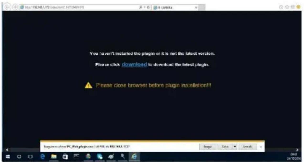
text_image
You haven't installed the plugin or it is not the latest version. Please click download to download the latest plugin. Please close browser before plugin installation!!! Explain this Web plugin.exe (.05.08) & 100,160,1.17?- Wait for plug-in download, after that confirm the ActiveX Installation.
- Select "Install" and wait for the installation is completed.

text_image
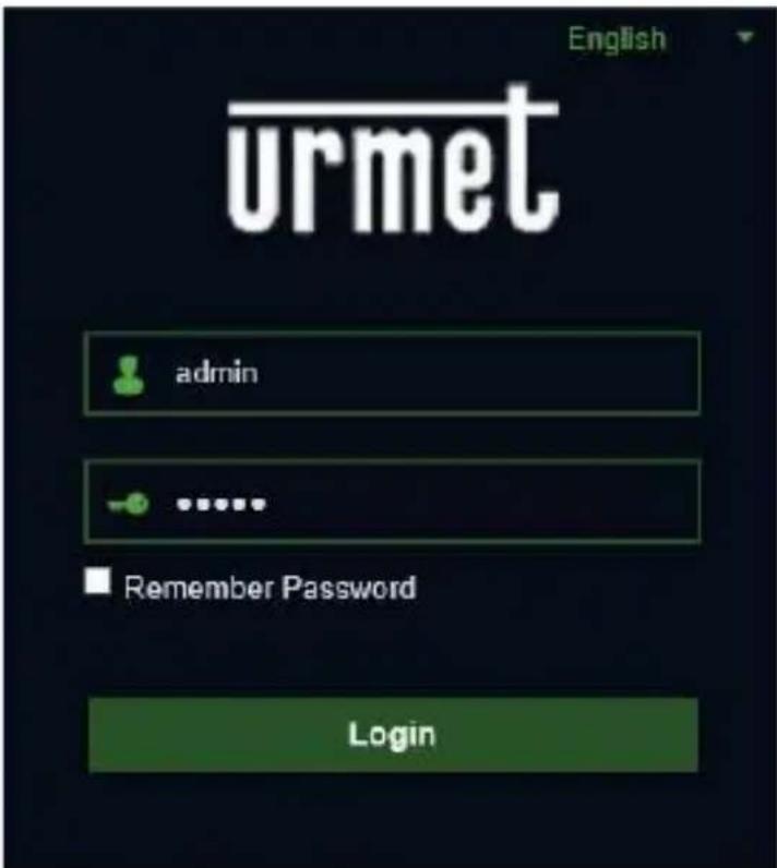
Setup - WebPlugin Ready to Install Setup is now ready to begin installing WebPlugin on your computer. Click Install to continue with the installation. Install Cancel- After completed the Active X installation, close the Internet Explorer Web Page and launch it again, put the IP Camera Address and the Login screen will be displayed. Select Username (default: admin), a Password (default: admin) and Language.
text_image
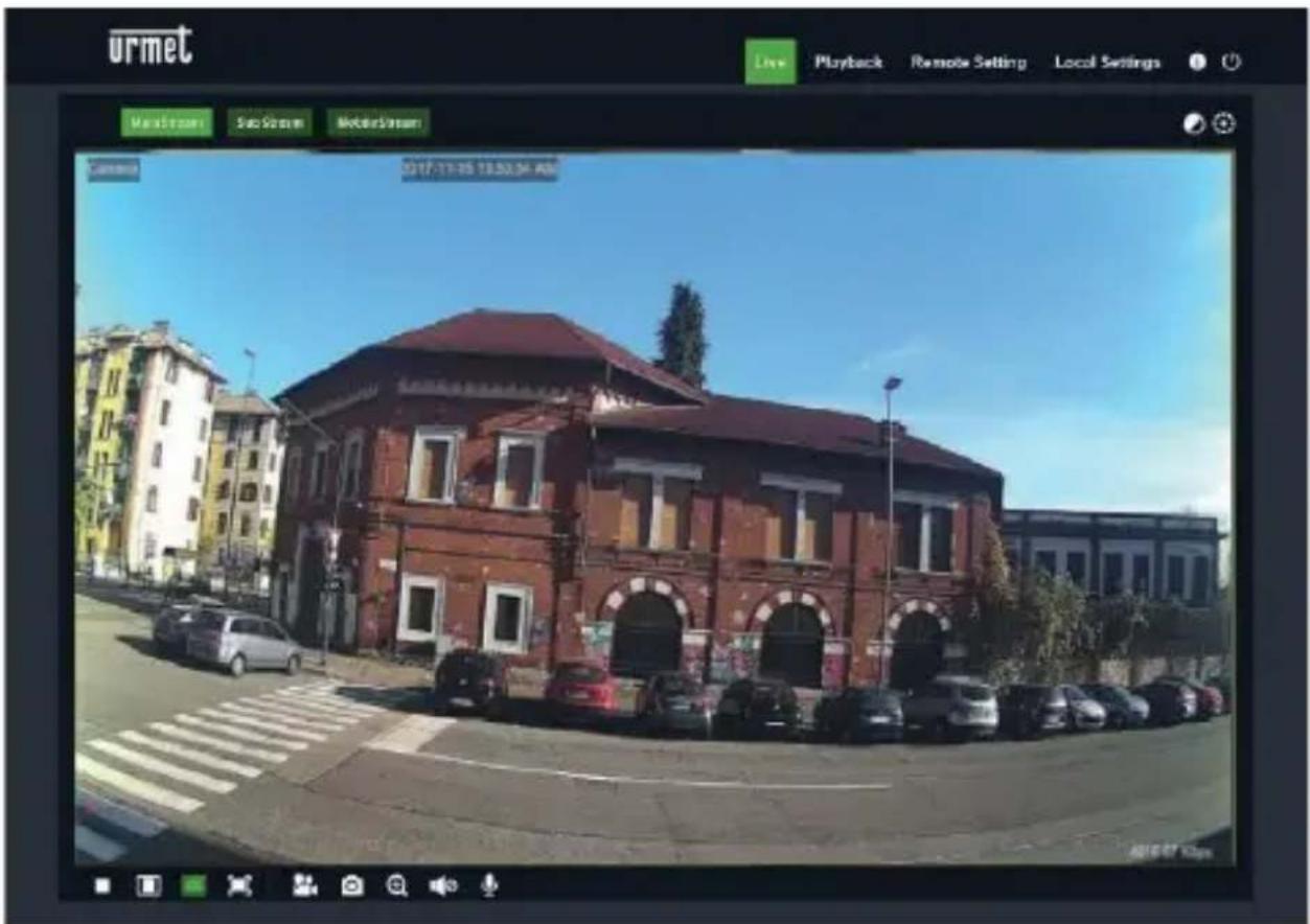
English urmet admin ...... Remember Password Login- Select "Login" in order to enter in LIVE screen.
text_image
urmet Live Playback Remote Setting Local Settings Max Street Sub Street Motor Street 2017/11/15 18:30:34 AM 2016-07 10pm- Click the buttons on the top left corner in the Web Page to select the stream to display (Main Stream, Sub Stream or Mobile Stream)
PTZ CONTROL
text_image
urmet Live Playback Exonic Setting Local Settings Play2 Player SubPlayer Middle Player PT2 Setting PT2 Speed 200046 F100A5 SOD26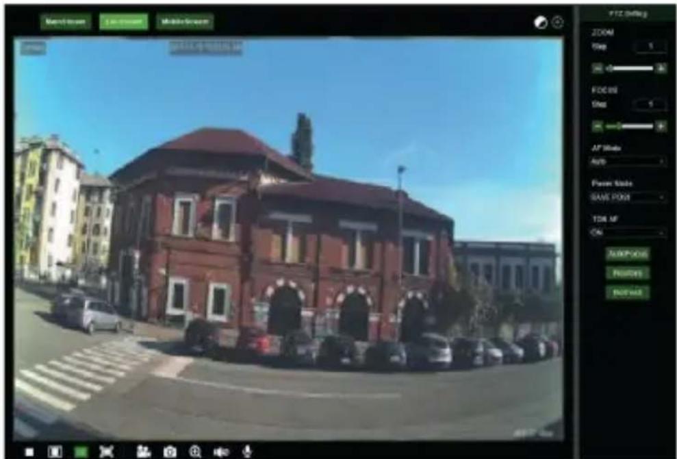
text_image
Moodi Street 1.0000000000 Multi-Service 2023/06/28 04:55:59 FID: 1 Stop: 1 FOOD: 1 Stop: 1 AF Mode Auto Power State SAVE POINT TDR AF CAI AVOPDOS Position BUTYAR
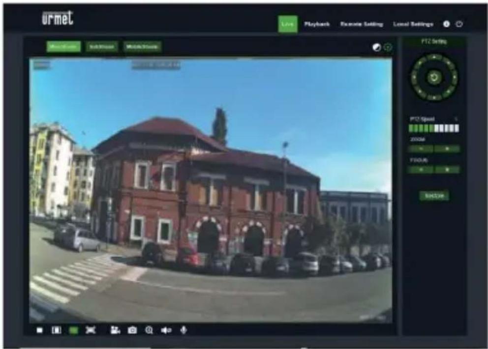
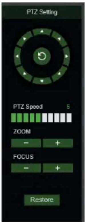
(PTZ control) select the icon to open the following window:
On Autofocus cameras with AF optics, the PTZ interface will be as follows:
text_image
PTZ Setting PTZ Speed 5 ZOOM - + FOCUS - + RestoreEight different angles can be selected on the circular control:
- PTZ Speed: 0 – 10 indicates different PTZ speeds.
• ZOOM zooms in and out.
• FOCUS increases or decreases FOCUS - Restore resets default settings.
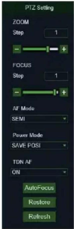
On Auto Focus cameras with DF optics, the PTZ interface will be as
text_image
PTZ Setting ZOOM Step 1 - + FOCUS Step 1 - + AF Mode SEMI Power Mode SAVE POSI TDN AF ON AutoFocus Restore Refreshfollows:
| Option | Value | Explanation |
| Zoom | Step/-/+ | Manually adjusts zoom (+ zoom in / - zoom out)Step: defines zooming speed |
| Focus | Step/-/+ | Manually adjusts focus (+ increase / - decrease)Step: defines focusing speed |
| AF MODE | SEMI + AUTO + MANUAL + OFF | This function is used to customise the camera focusing mode. Possible options are:SEMI: focusing is performed only after the zooming operations are finished.AUTO: focusing is adjusted automatically.MANUAL: focusing is adjusted manually.OFF: focusing and zoom are deactivated. Activate this option after having adjusted focus and zoom as required |
| ONE SHOT AF | / | Function not available. |
| TDN AF | ON + OFF | This function, when activate, allows automatic focus adjustment at each day -> night or night -> day switch. |
| LENS INIT | / | This re-initialises the optics and obtained optical calibration. To be performed when the camera is installed for the first time and in case of movements with consequent change of the framed picture.IMPORTANT: do not use with AF MODE equal to OFF |
| POWER MODE | SAVE POSI + OFF + WIDE | This is used to adjust the zoom whenever the camera is switched back on.SAVE POSI: this holds the zoom position set before the camera was switched off.OFF: do not save the settings stored before switch-off.WIDE: the camera is switched on in Wide mode. |
| AutoFocus | / | Adjusts focus automatically |
| Restore | / | Resets PTZ interface default settings (including focus) |
| Refresh | / | Updates the PTZ interface with changes to parameters (including focus) |
MOTION ALARM MANAGEMENT
The camera is capable of generating alarms when it detects movements.
It is possible to enable this function, in the Remote Setting, within the Alarm → Motion menu
PIR ALARM MANAGEMENT
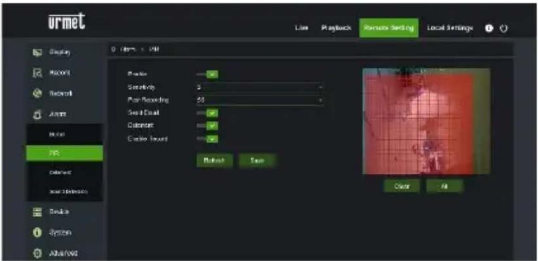
The camera is equipped with an infrared (PIR) sensor capable of generating presence detection alarms.
To enable and configure this function, select the Alarm>PIR menu in the Remote Setting
text_image
urmet Line Playback Person's Setting Local Settings Display Record Network Audio New PR Delete New Extension Audio System ADAMS 0.10m x 500 Speaker Sensitivity Poor Recording Seat Seat Cohort Cable Record Retroch San Clear AltThe configuration parameters are as follows:
- Enable: allows you to enable detection using the PIR sensor
• Sensitivity: establishes the sensitivity of the alarm detection
• Post Recording: establishes the number of seconds of recording
• Send Email: establishes whether to send an email in case of alarm
• Deterrent: establishes whether to activate the deterrent actions - Enable record: establishes and enables video recording
DETERRENCE FUNCTION CHECK (only for model 1099/208)
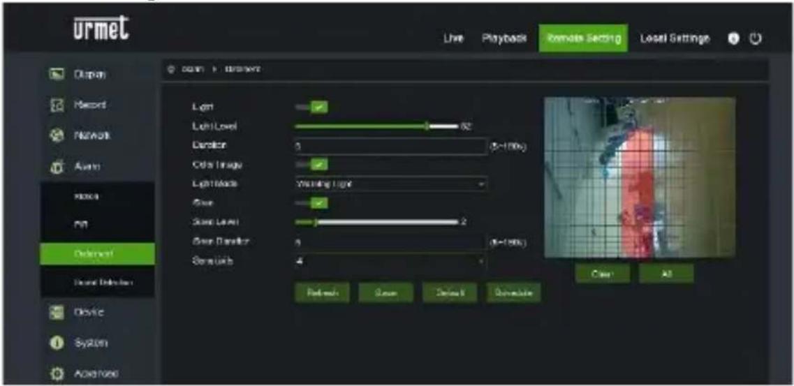
This function allows the camera to emit visual and audible signals in the event of an alarm.
To enable and configure this function, select the Alarm→Deterrence menu in the Remote Setting
text_image
urmet Live Playback Remote Setting Local Settings Display Record Network Audio Video Photo Defervert Sound Detachment Device SyRan Audio Light Level 62 Duration 5 (0-100s) Cable Image Light Mode Warning Light Glow Glow Level 2 Glow Diameter 4 (0-100s) Glow Width 4 Face mask Screen Default Transform Case AllThe configuration parameters are as follows:
• Light: allows you to enable the alarm light emission
• Light Level: establishes the light intensity value of the flash
• Duration: establishes the duration of the light signal
• Color image: establishes whether the image examined to generate the alarm is in color or in black / white
• Light Mode: establishes the type of light emission, fixed or stroboscopic
• Siren: allows you to enable the alarm sound emission
• Siren Level: establishes the sound intensity value of the signal
• Siren Duration: : establishes the duration of the sound signal
• Sensitivity: : establishes the sensitivity of the alarm detection
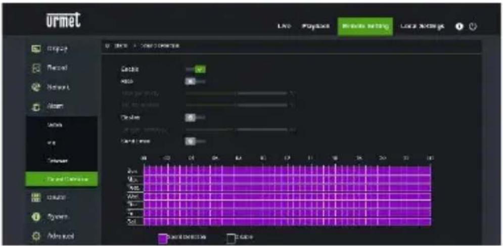
SOUND ALARM MANAGEMENT
The camera is equipped with a microphone capable of generating alarms in the presence of noises.
To enable and configure this function, select the Alarm → Sound Detection menu in the Remote Setting
text_image
urmet LNG PopStock MRKOS NETPG Lock NOKING 0 Control > Control > Compression Cable Audio Power Volume Audio Clash Audio Clash Audio Power Audio Audio Audio Audio Audio Audio Audio Audio Audio Audio Audio Audio Audio Audio Audio Audio Audio Audio Audio Audio Audio Audio Audio Audio Audio Audio Audio Audio Audio Audio Audio Audio Audio Audio Audio Audio Audio Audio Audio Audio Audio Audio Audio Audio Audio Audio Audio Audio Audio Audio AuctionThe configuration parameters are as follows:
- Enable: allows you to enable noise detection
- Rise: establishes that the alarm is generated with a sound of increasing intensity
- Decline: establishes that the alarm is generated with a sound of decreasing intensity
• Send Email: determines whether to send an email in the event of an alarm
Finally, the scheduler allows you to enable detection based on time schedule
Mobile software
Mobile Software is used for the iOS (iPhone, iPad) and Android platforms (Android Smartphone, Tablet). The following is a description of the Mobile Client Software.
SMARTPHONE DEVICE
Urmet iUVS plus Mobile Software
Urmet iUVS plus is a TVCC application for iOS and Android on smartphones, pads and tablets that is compatible with all URMET devices, both IPCam (Codec H265) and DVR/NVR/HVR (all codecs).
iUVS Plus can be downloaded from Play Store to the following link:
text_image
QR code image containing encoded data, no visible human-readable textiUVS Plus can be downloaded from Apple Store to the following link:
text_image
QR code image containing encoded data, no visible human-readable textMain features:
• Multichannel audio/video live streaming
• Multichannel remote playback
- Double stream playback
• Fisheye Camera support in Live and Playback modes
- Alarm notifications
- Custom single video stream configuration
• Video signal format management 4:3 - 16:9
- Local playback
• Video signal in portrait or landscape mode
• Device list export function
• Image sharing on social media/remote drives and personal clouds
• PTZ
• Image and Video capture
- Multi-device support
IMPORTANT NOTE
For more details about how to use the App and the features description please refer to the IP Camera user manual or online support available in Urmet iUVS Plus.
CORRECT DISPOSAL OF THIS PRODUCT
DIRECTIVE 2012/19/EU OF THE EUROPEAN PARLIAMENT AND OF THE COUNCIL of 4 July 2012 on waste electrical and electronic equipment (WEEE)The symbol of the crossed-out wheeled bin on the product or on its packaging indicates that this product must not be disposed of with
your other household waste.
Instead, it is your responsibility to dispose of your waste equipment by handing it over to a designated collection point for the recycling of waste electrical and electronic equipment.
The separate collection and recycling of your waste equipment at the time of disposal will help to conserve natural resources and ensure that it is recycled in a manner that protects human health and the environment.
For more information about where you can drop off your waste equipment for recycling, please contact your local city office, your household waste disposal service or the shop where you purchased the product
EN
The updated version of this quick start guide, the complete manual, the software and firmware of the devices are available for download at www.urmet.com. Open the page dedicated to the product by scanning the QR code below with your smartphone and then select the section DOCUMENTATION AND RESOURCES.
1099/500

text_image
QR code image containing encoded data, no visible human-readable text1099/502 1099/552
1099/501

text_image
QR code image containing encoded data, no visible human-readable text
text_image
QR code image containing encoded data, no visible human-readable text
text_image
QR code image containing encoded data, no visible human-readable text1099/551
text_image
QR code image containing encoded data, no visible human-readable text1099/460
1099/400
text_image
QR code image containing encoded data, no visible human-readable text1099/461
1099/550
text_image
QR code image containing encoded data, no visible human-readable text1099/553
text_image
QR code image containing encoded data, no visible human-readable text1099/401
text_image
QR code image containing encoded data, no visible human-readable text1099/462

text_image
QR code image containing encoded data, no visible human-readable text1099/208
text_image
QR code image containing encoded data, no visible human-readable text
text_image
QR code image containing encoded data, no visible human-readable text
text_image
QR code image containing encoded data, no visible human-readable textGuide rapide
H.265 IP CAMERA SERIES
INDICE
INDICE....50
Generalites 51
AVERTISSEMENTS 51
Installation 54
INSTALLATION BULLET CAMERA....54
INSTALLATION MINI DOME CAMERA 57
INSTALLATION CAMERA MINI DOME 58
INSTALLATION VANDAL-PROOF DOME CAMERA 60
Configurations IP de l'unite de filmage 61
CONNEXION SUR RESEAU IP AVEC SERVICE DHCP....61
COMMANDE PTZ 65
GESTION ALARME DETECTION DE MOUVEMENT 68
natural_image
Close-up of a camera lens component with yellow directional arrows indicating components (no text or symbols)natural_image
Interior view of an electronic device showing a circuit board with wires and a yellow arrow pointing to a component labeled 'AT10' (no readable text or symbols beyond labels)text_image
Collier ②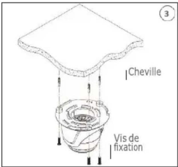
text_image
Cheville Vis de fixation ③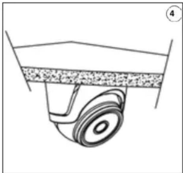
natural_image
Diagram of a mechanical component with a wheel and textured surface (no text or symbols)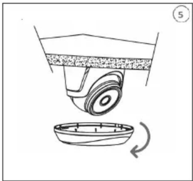
natural_image
Diagram of a mechanical device with a rotating base and a curved component, no text or symbols present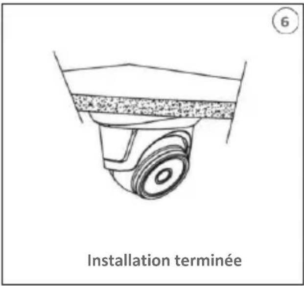
text_image
6 Installation terminéenatural_image
Exploded view diagram of a mechanical assembly showing internal components (no text or labels)INSTALLATION CAMERA MINI DOME
Fixation au plafond
text_image
4 CalotteInstallation Carte SD
natural_image
Close-up of a mechanical component with a yellow arrow pointing to a specific part (no visible text or symbols)text_image
You haven't installed the plugin or it is not the latest version. Please click download to download the latest plugin. Please close browser before plugin installation !!! Configure a sub on PC, Web, pluginbase (1.6) (U) to 192.168.1.52?text_image
Setup - WebPlugin Ready to Install Setup is now ready to begin installing WebPlugin on your computer. Click Install to continue with the installation. Install Canceltext_image
urmet Line Playback Rensor Setting Local Settings Display Report Network Access Division File Options Asset/Deletion Device System Advanced 0.000x 100% Mouse Use Safari MAC Marketing Send Email Deformation Device Record Mouse Save Clear OKtext_image
urmet Live Playback Remote Setting Local Settings Display Record Network Avon Photo Play Deletion Sound Detector Device System Audio Light Light Level Daristor 5 (0-100x) Other Image Light Mode Warning Light Glow Glow Level 2 (0-100x) Glow Daristor 5 (0-100x) Glow Light 4 Refresh Save Default Remove Clear Alltext_image
QR code image containing encoded data, no visible human-readable texttext_image
QR code image containing encoded data, no visible human-readable texttext_image
QR code image containing encoded data, no visible human-readable text
text_image
QR code image containing encoded data, no visible human-readable text
text_image
1099/551
text_image
1099/400
text_image
1099/401
text_image
1099/460
text_image
1099/461
text_image
QR code image containing encoded data, no visible human-readable text
text_image
1099/208Schnellanleitung
H.265 IP CAMERA SERIES
INDEX
INDEX 74
ALARM PIR SENSOR....92
natural_image
Close-up of a black mechanical component with yellow arrows pointing to features, no visible text or symbols.natural_image
Interior view of an electronic device showing a circuit board with wires and a yellow arrow pointing to a component (no readable text or symbols)natural_image
Diagram of a mechanical component with a wheel and textured surface (no text or symbols)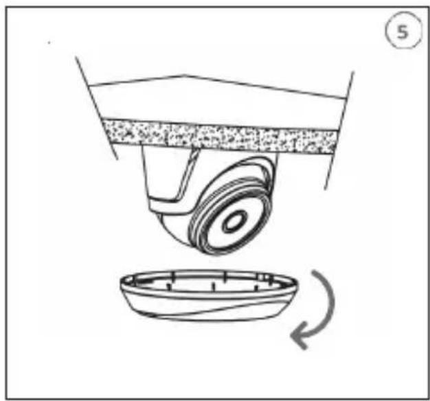
natural_image
Diagram of a mechanical device with a rotating base and a curved component, no text or symbols present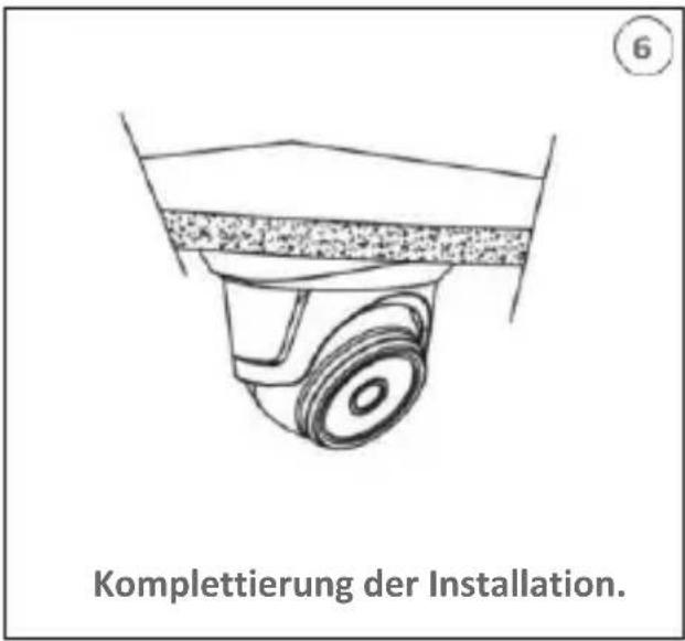
natural_image
Exploded view diagram of a mechanical assembly showing internal components (no text or labels)INSTALLATION DER MINI-FLAT KAMERA
Deckenmontage
natural_image
Close-up of a mechanical component with a yellow arrow pointing to a specific area (no visible text or symbols)text_image
User Info Username admin Password ***** Device Info Start IP Media Port Web Port Gateway Net Mask Net Mode Static ModifyNutzername (UserName): admin Passwort (Password): admin Media Port: 9988
text_image
You haven't installed the plugin or it is not the latest version. Please click download to download the latest plugin. Please close browser before plugin installation!!text_image
Setup - WebPlugin Ready to Install Setup is now ready to begin installing WebPlugin on your computer. Click Install to continue with the installation, or click Back if you want to review or change any settings. Destination location: C:\Users\vermeburg\AppData\Roaming\WebPlugins\IPC2\EPFChrome Start Menu folder: WebPlugins\IPC2 Web Plugin Install Canceltext_image
urmet Line Playback Rensor Setting Local Settings Display Record Networks Access Show File Delete Delete Acord/Delusion Breaker System Advanced 9 Muns > File Music Customs Music Marketing Send Email Collected Creative Record Refresh Save OK Canceltext_image
urmet Live Playback Remote Setting Local Settings Display Record Network Avon Noise Pit Defense Speed Retention Device System Audio feed Light Light Level Duration 0 (1-1MHz) Color Image Light Mode Verming Light Size Size Level Size Duration 4 (5-100x) Size Units 4 Refresh Save Reset Override 确定 Alltext_image
QR code image containing encoded data, no visible human-readable texttext_image
QR code image containing encoded data, no visible human-readable textHauptfunktionen:
text_image
QR code image containing encoded data, no visible human-readable text1099/502 1099/552
1099/501
text_image
QR code image containing encoded data, no visible human-readable text
text_image
QR code image containing encoded data, no visible human-readable text1099/400
1099/550
text_image
QR code image containing encoded data, no visible human-readable text1099/553
text_image
QR code image containing encoded data, no visible human-readable text1099/551

text_image
QR code image containing encoded data, no visible human-readable text1099/460
text_image
QR code image containing encoded data, no visible human-readable text1099/461
text_image
QR code image containing encoded data, no visible human-readable text1099/401
text_image
QR code image containing encoded data, no visible human-readable text1099/462
text_image
QR code image containing encoded data, no visible human-readable text1099/208
text_image
QR code image containing encoded data, no visible human-readable text
text_image
QR code image containing encoded data, no visible human-readable text
text_image
QR code image containing encoded data, no visible human-readable texttext_image
QR code image containing encoded data, no visible human-readable texttext_image
QR code image containing encoded data, no visible human-readable textFor assistance and information about Urmet products and systems you can scan this QR code with your smartphone or visit
www.urmet.com >> Contacts >> Export Sales Network
Urmet S.pA. reserves the right to make changes to its products at any time, without prior notice.
Released in July 2019.
www.urmet.com | info@urmet.com
All Urmet products bear the mark C €
Made in China to Urmet specifications.
urmet
urmet

Customer Care
Italia: 011 23 39 810
Export Dept.: +39 011 24 00 250/256
MADE IN CHINA
To Urmet Specification

urmet
URMET S.p.A.
Via Bologna, 188/C | 10154 Torino (ITALY)
www.urmet.com | info@urmet.com