SU-G700M2 - Hi-fi system PANASONIC - Free user manual and instructions
Find the device manual for free SU-G700M2 PANASONIC in PDF.

User questions about SU-G700M2 PANASONIC
0 question about this device. Answer the ones you know or ask your own.
Ask a new question about this device
Download the instructions for your Hi-fi system in PDF format for free! Find your manual SU-G700M2 - PANASONIC and take your electronic device back in hand. On this page are published all the documents necessary for the use of your device. SU-G700M2 by PANASONIC.
USER MANUAL SU-G700M2 PANASONIC
Music is borderless and timeless, touching people's hearts across cultures and generations.
Each day the discovery of a truly emotive experience from an unencountered sound awaits.
Let us take you on your journey to rediscover music.
Delivering the Ultimate Emotive Musical Experience to All
At Technics we understand that the listening experience is not purely about technology but the magical and emotional relationship between people and music.
We want people to experience music as it was originally intended and enable them to feel the emotional impact that enthuses and delights them.
Through delivering this experience we want to support the development and enjoyment of the world's many musical cultures. This is our philosophy.
With a combination of our love of music and the vast high-end audio experience of the Technics team, we stand committed to building a brand that provides the ultimate emotive musical experience by music lovers, for music lovers.
text_image
Michoke OgawaThank you for purchasing this product.
Please read these instructions carefully before using this product, and save this manual for future use.
- About descriptions in this Owner's Manual
- Pages to be referred to are indicated as “⇒ ∞”.
- The illustrations shown may differ from your unit.
If you have any questions, visit:
U.S.A.: http://shop.panasonic.com/support
Canada: http://panasonic.ca/english/support
Register online at https://shop.panasonic.com/RegisterTechnics (U.S. customers only)
Features
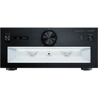
Integrated amplifier achieves incredibly clear and dynamic sound quality
The JENO Engine transmits and processes audio signals in full digital with minimal jitter from the input stage to the power stage. The LAPC enables an ideal impulse response for any type of speaker. Moreover, the Advanced Speed Silent Power Supply achieves both high-speed switching and low noise. With these features, the amplifier realizes the excellent drive capability and dynamic sound full of energy as well as full digital, clear sound.
Maximally reduces noise and vibrations to achieve dynamic sound reproduction with the build quality appealing to listeners' sensibilities
The interior of this unit is divided into three independent sections by inner chassis to create the power supply section as a source of noises, power amplifier section handling high currents, and terminal section handling fine signals. In addition to this three-section construction that eliminates mutual noise effects, the Double Steel Plate Chassis that consists of the high-rigidity inner chassis and the bottom chassis with 2 mm steel plate is provided to maximally reduce noise and vibrations.
The large twin peak power meter on the front panel vividly displays the dynamics of the sound. The volume knob with circular finish uses pure solid aluminium for superior operational feeling. The excellent build quality appeals to listeners' sensibilities.
Supports from analog to digital sound sources with various high-quality sound technologies
Compatible with MM/MC cartridge, and equipped with various high-quality sound technologies, such as low-noise PHONO circuit to realize record reproduction with a better S/N ratio, high-quality ruby mica condenser for USB input, Digital Noise Isolation Architecture with power conditioner by non-magnetism carbon film resistance, and Optimally Activated Circuit System to minimize inner noise by partially stopping unnecessary circuit blocks.
Table of contents
| IMPORTANT SAFETY INSTRUCTIONS | 06 | Please carefully read the “IMPORTANT SAFETY INSTRUCTIONS” of this manual before use. |
| Control reference guide 08 | This unit, Remote control | |
| Connections 12 | Speaker connection, AC power supply cord connection | |
| Operations 14 | Playing back connected devices | |
| Settings 22 | Other settings, Using output correction function (LAPC) | |
| Others 28 | Troubleshooting, Specifications, etc. |
Accessories
AC power supply cord (1) K2CG3YY00191
Remote control (1) N2QAYA000143
Batteries for remote control (2)

(ONLY FOR CANADA)
The enclosed Canadian French label sheet corresponds to the English display on the unit.
- Product numbers provided in this Owner's Manual are correct as of August 2021.
• These may be subject to change. - Do not use AC power supply cord with other equipment.

Information on Disposal in other Countries outside the European Union. This symbol is only valid in the European Union.
If you wish to discard this product, please contact your local authorities or dealer and ask for the correct method of disposal.
IMPORTANT SAFETY INSTRUCTIONS
Read these operating instructions carefully before using the unit. Follow the safety instructions on the unit and the applicable safety instructions listed below. Keep these operating instructions handy for future reference.
1 Read these instructions.
2 Keep these instructions.
3 Heed all warnings.
4 Follow all instructions.
5 Do not use this apparatus near water.
6 Clean only with dry cloth.
7 Do not block any ventilation openings. Install in accordance with the manufacturer's instructions.
8 Do not install near any heat sources such as radiators, heat registers, stoves, or other apparatus (including amplifiers) that produce heat.
9 Do not defeat the safety purpose of the polarized or grounding-type plug. A polarized plug has two blades with one wider than the other. A grounding-type plug has two blades and a third grounding prong. The wide blade or the third prong are provided for your safety. If the provided plug does not fit into your outlet, consult an electrician for replacement of the obsolete outlet.
10 Protect the power cord from being walked on or pinched particularly at plugs, convenience receptacles, and the point where they exit from the apparatus.
11 Only use attachments/accessories specified by the manufacturer.
12 Use only with the cart, stand, tripod, bracket, or table specified by the manufacturer, or sold with the apparatus. When a cart is used, use caution when moving the cart/ apparatus combination to avoid injury from tip-over.
13 Unplug this apparatus during lightning storms or when unused for long periods of time.
14 Refer all servicing to qualified service personnel. Servicing is required when the apparatus has been damaged in any way, such as power-supply cord or plug is damaged, liquid has been spilled or objects have fallen into the apparatus, the apparatus has been exposed to rain or moisture, does not operate normally, or has been dropped.
Warning
Unit
• To reduce the risk of fire, electric shock or product damage,
- Do not expose this unit to rain, moisture, dripping or splashing.
- Do not place objects filled with liquids, such as vases, on this unit.
- Use only the recommended accessories.
- Do not remove covers.
- Do not repair this unit by yourself. Refer servicing to qualified service personnel.
- Do not let metal objects fall inside this unit.
- Do not place heavy items on this unit.

AC power supply cord
- The power plug is the disconnecting device. Install this unit so that the power plug can be unplugged from the socket outlet immediately.
- Ensure the earth pin on the power plug is securely connected to prevent electrical shock.
- An apparatus with CLASS I construction shall be connected to a power socket outlet with a protective earthing connection.
Caution
Unit
- Do not place sources of naked flames, such as lighted candles, on this unit.
- This unit may receive radio interference caused by mobile telephones during use. If such interference occurs, please increase separation between this unit and the mobile telephone.
- Do not touch the top surface of this unit. This unit becomes hot while it is on.
Placement
- Place this unit on an even surface.
• To reduce the risk of fire, electric shock or product damage, - Do not install or place this unit in a bookcase, built-in cabinet or in another confined space. Ensure this unit is well ventilated.
- Do not obstruct this unit's ventilation openings with newspapers, tablecloths, curtains, and similar items.
- Do not expose this unit to direct sunlight, high temperatures, high humidity, and excessive vibration.
- Ensure that the placement location is sturdy enough to accommodate the weight of this unit ( 31).
- Keep your speakers at least 10 mm ^3 ( _32 ") away from the system for proper ventilation.
- Do not lift or carry this unit by holding the knobs. Doing so may cause this unit to fall, resulting in personal injury or malfunction of this unit.
Battery
- Danger of explosion if battery is incorrectly replaced. Replace only with the type recommended by the manufacturer. - Mishandling of batteries can cause electrolyte leakage and may cause a fire.
- Remove the battery if you do not intend to use the remote control for a long period of time. Store in a cool, dark place.
- Do not heat or expose to flame.
- Do not leave the battery(ies) in a car exposed to direct sunlight for a long period of time with doors and windows closed.
- Do not take apart or short circuit.
- Do not recharge alkaline or manganese batteries.
- Do not use batteries if the covering has been peeled off.
- Do not mix old and new batteries or different types at the same time.
- When disposing of the batteries, please contact your local authorities or dealer and ask for the correct method of disposal.
- Avoid the use in the following conditions
- High or low extreme temperatures during use, storage or transportation.
- Replacement of a battery with an incorrect type.
- Disposal of a battery into fire or a hot oven, or mechanically crushing or cutting of a battery, that can result in an explosion.
- Extremely high temperature and/or extremely low air pressure that can result in an explosion or the leakage of flammable liquid or gas.
Installation
- Turn off all equipment before connection and read the appropriate operating instructions.
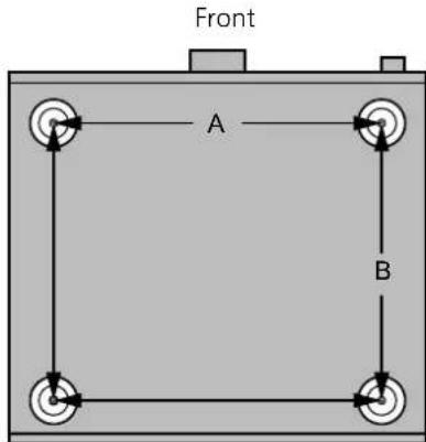
• For the dimensions of this unit (⇒ 31) - Refer to the following figure for the dimensions of this unit's legs.
text_image
Front A BA: 340 mm (13 ^25 /64")
B: 285 mm (11 ^7 / _32 ")

CAUTION
RISK OF ELECTRIC SHOCK DO NOT OPEN

CAUTION: TO REDUCE THE RISK OF ELECTRIC SHOCK, DO NOT REMOVE SCREWS. NO USER-SERVICEABLE PARTS INSIDE. REFER SERVICING TO QUALIFIED SERVICE PERSONNEL.

The lightning flash with arrowhead symbol, within an equilateral triangle, is intended to alert the user to the presence of uninsulated "dangerous voltage" within the product's enclosure that may be of sufficient magnitude to constitute a risk of electric shock to persons.

The exclamation point within an equilateral triangle is intended to alert the user to the presence of important operating and maintenance (servicing) instructions in the literature accompanying the appliance.
Conforms to UL STD 62368-1.
Certified to CAN/CSA STD C22.2 No.62368-1.
THE FOLLOWING APPLIES ONLY IN CANADA.
CAN ICES-3(B)/NMB-3(B)
THE FOLLOWING APPLIES ONLY IN THE U.S.A. FCC Note:
This equipment has been tested and found to comply with the limits for a Class B digital device, pursuant to Part 15 of the FCC Rules.
These limits are designed to provide reasonable protection against harmful interference in a residential installation. This equipment generates, uses, and can radiate radio frequency energy and, if not installed and used in accordance with the instructions, may cause harmful interference to radio communications.
However, there is no guarantee that interference will not occur in a particular installation. If this equipment does cause harmful interference to radio or television reception, which can be determined by turning the equipment off and on, the user is encouraged to try to correct the interference by one or more of the following measures:
- Reorient or relocate the receiving antenna.
- Increase the separation between the equipment and receiver.
- Connect the equipment into an outlet on a circuit different from that to which the receiver is connected.
- Consult the dealer or an experienced radio/TV technician for help.
FCC Caution: To assure continued compliance, follow the attached installation instructions and use only shielded interface cables when connecting to peripheral devices.
Any changes or modifications not expressly approved by the party responsible for compliance could void the user's authority to operate this equipment.
This device complies with Part 15 of the FCC Rules. Operation is subject to the following two conditions:
(1) This device may not cause harmful interference, and (2) this device must accept any interference received, including interference that may cause undesired operation.
Supplier's Declaration of Conformity
Trade Name: Technics
Model No.: SU-G700M2
Responsible Party:
Panasonic Corporation of North America
Two Riverfront Plaza, Newark, NJ 07102-5490
Support Contact:
http://shop.panasonic.com/support
text_image
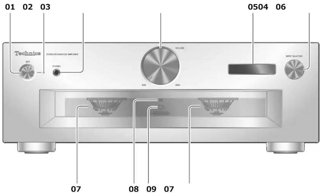
01 02 03 Technics AUDIO INTEGRATED AMPLIERS PHONES VOLUME MIN MAX 0504 06 INPUT SELECTOR 07 08 09 0701 Standby/on button( )
- Press to switch the unit from on to standby mode or vice versa. In standby mode, the unit is still consuming a small amount of power.
02 Power indicator
- Blue: The unit is on.
- Off: The unit is in standby mode.
03 Headphones jack
- When a plug is connected, the speakers and PRE OUT terminals do not output sound. ( 20)
- Sound is not output from headphones jack when using this unit as main amplifier ("MAIN IN" is selected as input source of this unit). ( 18)
- Excessive sound pressure from earphones and headphones can cause hearing loss.
- Listening at full volume for long periods may damage the user's ears.
04 Volume knob
• -- dB (min), -88.0 dB to 0 dB (max)
05 Display
• Information such as input source, etc. is displayed. (⇒ 30)
06 Input selector knob
- Turn this knob clockwise or anticlockwise to switch the input source.
07 Peak power meter
- Display the output level. 100 % is the rated output (⇒ 31).
- Peak power meter does not work while the light is turned off by pressing [DIMMER], connecting the headphones, etc.
08 LAPC indicator (⇒ 24)
09 Remote control signal sensor
- Reception distance: Within approx. 7 m (23 ft) directly in front
- Reception angle: Approx. 30^ left and right
text_image
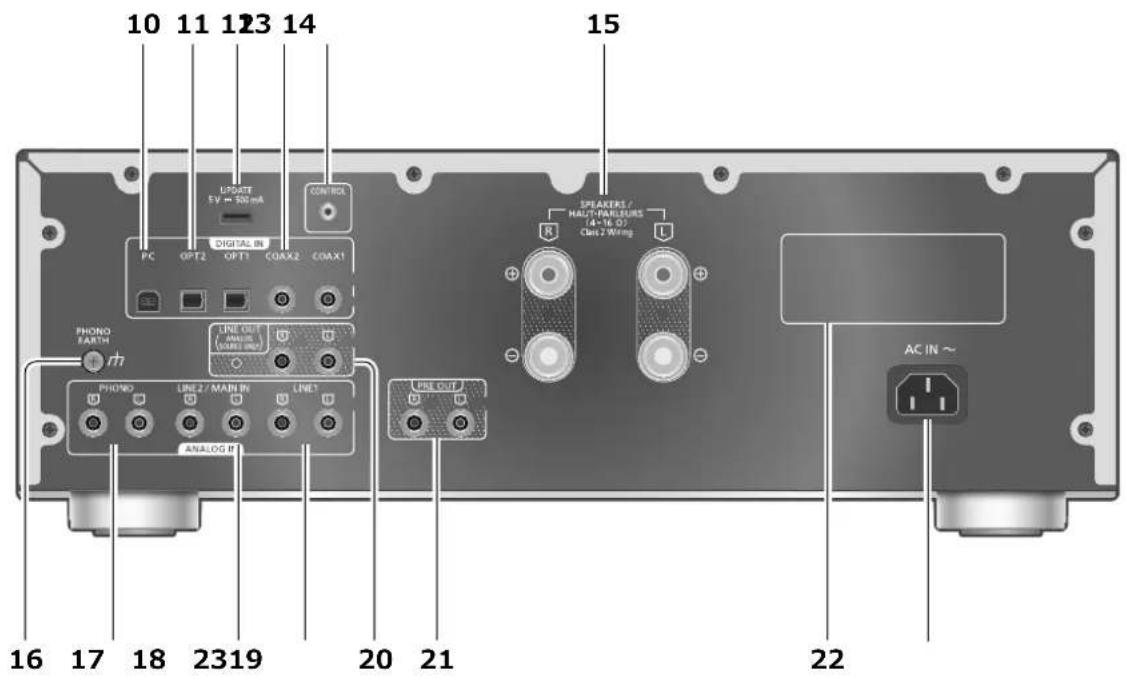
10 11 123 14 UPORT 5V = 500 mA CONTROL PC OPT2 OPT11 COAX2 COAX1 PHONO EARTH LINE OUT / ANALOG IN (WARI) UNIT ANALOG IN PHONO LINE 2 / MAIN IN LINE 3 PRO OUT SPEAKERS / HALO-MARELERS (4-16.0) Cbit 2 Wiring AC IN ~ 16 17 18 2319 20 21 2210 USB-B terminal
- For connecting to a PC, etc. (⇒ 15)
11 Optical digital input terminals (OPT1/OPT2) (⇒ 14)
12 UPDATE terminal (USB-A) (DC 5 V---500 mA) ( 25)
13 Coaxial digital input terminals (COAX1/COAX2) ( 14)
14 System terminal (CONTROL) (⇒ 26)
15 Speaker output terminals (⇒ 12)
16 PHONO EARTH terminal (⇒ 16)
- For connecting the ground wire of a turntable.
17 Analog audio input terminals (PHONO) (⇒ 16)
- Please use the cable less than 3 m.
18 Analog audio input terminals (LINE2/MAIN IN)
• These input terminals are combined with LINE2 and MAIN IN. Switch the function according to the connected equipment. (⇒ 17, 18)
19 Analog audio input terminals (LINE1) (⇒ 16)
20 Analog audio output terminals (LINE OUT) ( 21)
21 Analog audio output terminals (PRE OUT) (⇒ 20)
22 Product identification marking • The model number is indicated.
23 AC IN terminal ( 13)
Using the remote control
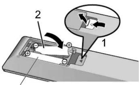
text_image
Diagram showing a device with labeled parts and directional arrows indicating movement or flow, including part 1 and part 2.R03/LR03, AAA
(Alkaline or manganese batteries)
Note
- Insert the battery so the terminals (⊕ and ⊕) match those in the remote control.
- Point it at the remote control signal sensor on this unit. ( 08)
- Keep the batteries out of reach of children to prevent swallowing.
text_image
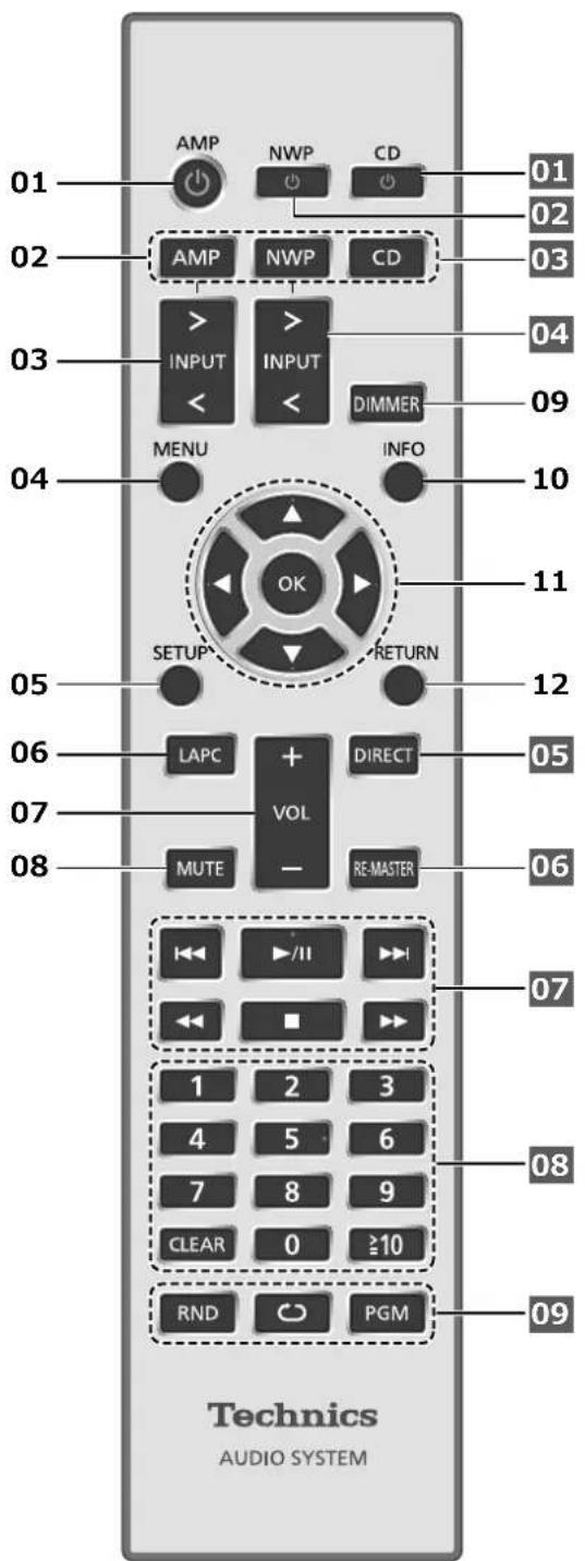
01 AMP NWP CD 01 02 03 02 AMP NWP CD 03 04 INPUT > > INPUT > > > > > > > > > > > > > > > > 09 04 MENU INFO 10 05 SETUP OK RETURN 11 12 LAPC + VOL DIRECT 05 07 MUTE - RE-MASTER 06 07 1 2 3 4 5 6 7 8 9 CLEAR 0 ≥10 08 RND PGM 09 Technics AUDIO SYSTEM01 [AMPQ]: Standby/on button
- Press to switch the unit from on to standby mode or vice versa. In standby mode, the unit is still consuming a small amount of power.
02 [AMP]/[NWP]/[CD]:
Select the device to be operated
03 [>INPUT<]: Switch the input source (⇒ 14, 15, 16, 17, 18)
04 [MENU]: Enter menu (⇒ 16, 17, 18, 19)*
05 [SETUP]: Enter setup menu ( 22) ^*
06 [LAPC]: Measure the output signal of the amplifier when speakers are connected, and correct its output ( 24)
07 [+VOL-]: Adjust the volume
- -- dB (min), -88.0 dB to 0 dB (max)
08 [MUTE]: Mute the sound
- Press [MUTE] again to cancel. "MUTE" is also cancelled when you adjust the volume with this unit or when you turn the unit to standby.
09 [DIMMER]: Adjust the brightness of the peak power meter light, display, etc.
- When the display is turned off, it will light up for a few seconds only when you operate this unit. Before the display turns off, "Display Off" will be displayed for a few seconds.
- Press repeatedly to switch the brightness.
- Peak power meter does not work while the light is turned off.
10 [INFO]: View content information ^†
- Press this button to display sampling frequency and other information. (The information varies depending on the input source.)
11 [▲], [▼], [ ]◀[ ]/[OK]: Selection/OK *
12 [RETURN]: Return to the previous display*
*: Press [AMP] first to operate this unit. (The remote control may work for other Technics devices and may not for this unit when pressing [NWP] or [CD].)
■ Buttons that work for Technics devices supporting system control function
The remote control of this unit also works for Technics devices supporting system control function (Network Audio Player, Compact Disc Player, etc.). For information on the operations of the devices, please also refer to their operating instructions.
01 [⏻] Standby/on switch for the Compact Disc Player
02 [⏻] Standby/on switch for the Network Audio Player
03 Select the device to be operated
04 Select the input source of the Network Audio Player
05 Turn on/off Direct mode
06 Turn on/off Re-master
07 Playback control buttons
08 Numeric buttons, etc.
09 Playback control buttons
Remote control mode
When other equipment responds to the supplied remote control, change the remote control mode.
- The factory default is "Mode 1".
1 Press [AMP].
2 Press [SETUP].
3 Press [▲], [▼] repeatedly to select "Remote Control" and then press [OK].
- The current remote control mode of this unit is displayed for a few seconds.
4 When "Set Mode 1/2" is displayed, change the remote control mode of the remote control.
To set "Mode 1":
Press and hold [OK] and [1] for at least 4 seconds.
To set "Mode 2":
Press and hold [OK] and [2] for at least 4 seconds.
5 Point the remote control at this unit, and press and hold [OK] for at least 4 seconds.
- When the remote control mode is changed, the new mode will appear on the display for a few seconds.
■ When "Remote 1" or "Remote 2" is displayed
When "Remote 1" or "Remote 2" is displayed, the remote control modes of this unit and remote control are different. Perform step 4 above.
Connections
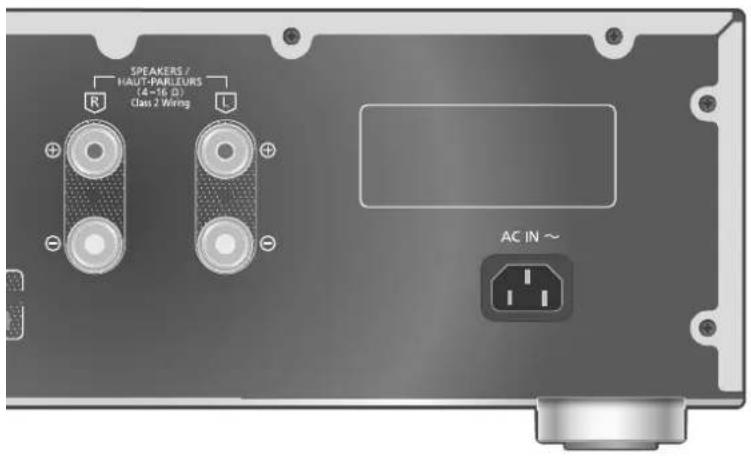
Speakers/AC power supply cord
• Use only the supplied AC power supply cord.
- Insert the plugs of the cables to be connected all the way in.
• Do not bend cables at sharp angles.
- This unit can measure the output signal of the amplifier and correct its output to make the optimum adjustment of speaker output. (⇒ 24)
- To optimize the audio output from the speakers, you can measure the amplifier output signal and correct its output when it is connected to the speakers. (⇒ 24)
text_image
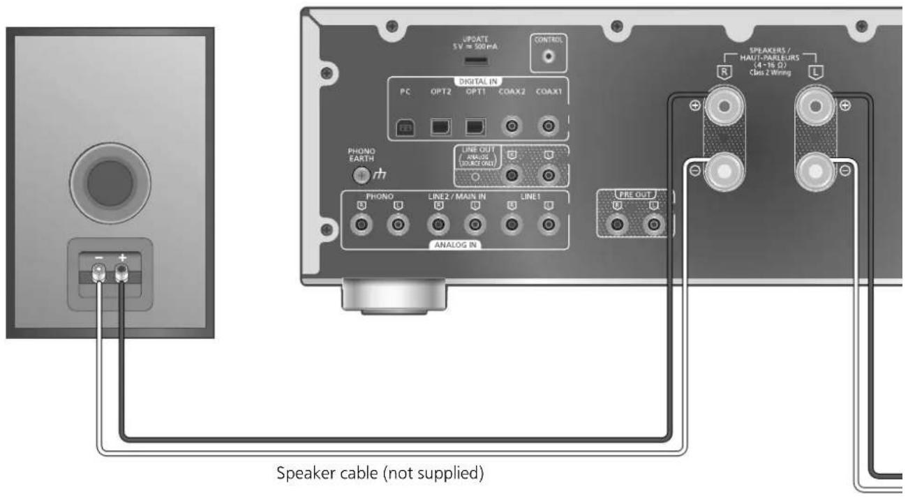
UPDATE 5V = 500mA CONTROL DIGITAL IN PC OPT2 OPT1 COAX2 COAX1 FEET PHONO EARTH rh LINE OUT (ANALOG SOURCE OUT) PROX LINE2 / MAIN IN LINE1 ANALOG IN PRE OUT SPEAKERS / HAU / DARLEURS (4-15 Ω) Class 2 Wiring Speaker cable (not supplied)Speaker connection
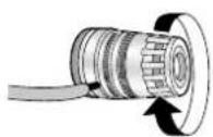
1 Turn the knobs to loosen them, and insert the core wires into the holes.
2 Tighten the knobs.

Note
- When the connections are completed, pull the speaker cables lightly to check that they are connected firmly.
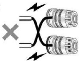
- Be careful not to cross (short-circuit) or reverse the polarity of the speaker wires as doing so may damage the amplifier.
DO NOT
text_image
Diagram showing a crossed electrical circuit with two cylindrical components and lightning bolts, marked with an 'X' symbol.- Wire the polarity (+/-) of the terminals correctly. Not doing so may adversely affect stereo effects or cause malfunction.
- For details, refer to the operating instructions of the speakers.
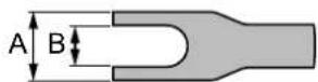
- Though the spade plug (A: 16 mm B ") or less, B: 8 mm ( ^5/16 ) or more) can be connected, some plug may not be connected depending on the shape of plug.
text_image
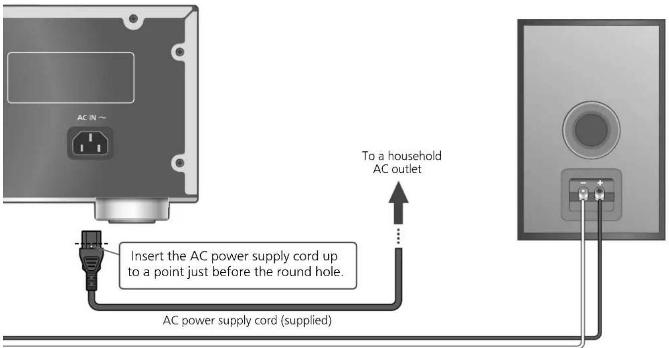
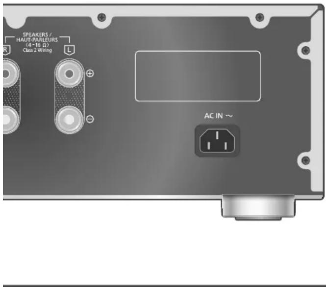
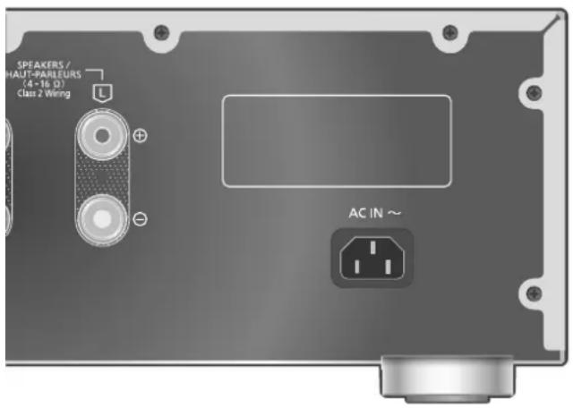
AC IN ~ Insert the AC power supply cord up to a point just before the round hole. To a household AC outlet AC power supply cord (supplied)Speaker cable (not supplied)
AC power supply cord connection
Connect only after all other connections are completed.
Note
- This unit consumes a small amount of AC power ( 31) even when the unit is in standby mode. Remove the plug from the main electrical outlet if you will not be using the unit for an extended period of time. Place the unit so the plug can be easily removed.
Speaker output correction (LAPC)
You can make the optimum adjustment according to your own speakers. ( 24)
Operations
Using digital audio output device
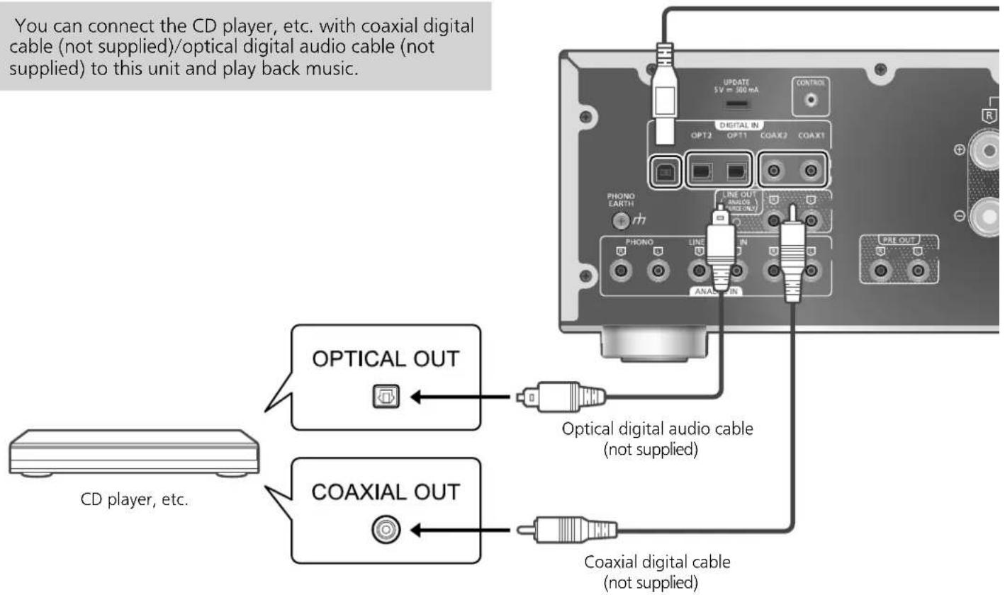
You can connect the CD player, etc. with coaxial digital cable (not supplied)/optical digital audio cable (not supplied) to this unit and play back music.
text_image
You can connect the CD player, etc. with coaxial digital cable (not supplied)/optical digital audio cable (not supplied) to this unit and play back music. OPTICAL OUT CD player, etc. Optical digital audio cable (not supplied) COAXIAL OUT Coaxial digital cable (not supplied)Using coaxial digital cable
1 Disconnect the AC power supply cord.
2 Connect this unit and a CD player, etc.
3 Connect the AC power supply cord to this unit. ( 13)
4 Press [AM∅] to turn this unit on.
5 Press [>INPUT<] repeatedly to select "COAX1" or "COAX2".
- You can also select the input source by turning the input selector knob on the unit.
6 Start playback on the connected device.
Note
- The digital audio input terminals of this unit can only detect the following linear PCM signals. For details, refer to the operating instructions of the connected device.
- Sampling frequency: Coaxial digital input 32/44.1/48/88.2/96/176.4/192 kHz Optical digital input 32/44.1/48/88.2/96 kHz - Number of quantization bits: 16/24 bit
Using optical digital audio cable
1 Disconnect the AC power supply cord.
2 Connect this unit and a CD player, etc.
3 Connect the AC power supply cord to this unit. ( 13)
4 Press [AMB] to turn this unit on.
5 Press [>INPUT<] repeatedly to select "OPT1" or "OPT2".
- You can also select the input source by turning the input selector knob on the unit.
6 Start playback on the connected device.
text_image
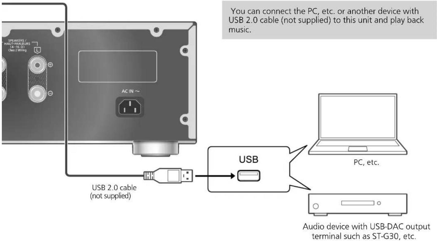
SPEAKERS / HAUT-PARIES/RS (4-TE 0) Class 2 Wiring AC IN ~ USB 2.0 cable (not supplied) USB PC, etc. Audio device with USB-DAC output terminal such as ST-G30, etc.■ Preparation
Connecting to a PC
- Before connecting to a PC, follow the steps below.
- Refer to the following for the recommend OS versions for your PC (as of August 2021):
- Windows 8.1, Windows 10
- macOS 10.12, 10.13, 10.14, 10.15, 11.0, 11.1, 11.2, 11.3, 11.4
① Download and install the dedicated USB driver to the PC. (Only for Windows OS)
- Download and install the driver from the website below. www.technics.com/support/
② Download and install the dedicated app "Technics Audio Player" (free of charge) on your PC.
- Download and install the app from the website below. www.technics.com/support/
Using USB 2.0 cable
1 Disconnect the AC power supply cord.
2 Connect this unit and a PC, etc.
3 Connect the AC power supply cord to this unit. ( 13)
4 Press [AM∅] to turn this unit on.
5 Press [>INPUT<] repeatedly to select "PC".
- You can also select the input source by turning the input selector knob on the unit.
6 Start playback using the dedicated app "Technics Audio Player" on the connected PC.
Note
- When connecting an audio device with USB-DAC output terminal such as ST-G30, etc., refer to the operating instructions of the connected device.
- About supported format, refer to "Specifications". (⇒ 31)
• Windows is a trademark or a registered trademark of Microsoft Corporation in the United States and other countries.
• macOS is a trademark of Apple Inc.
Operations
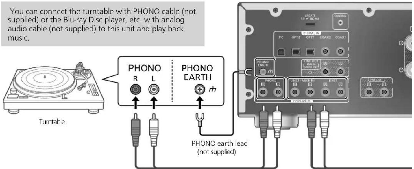
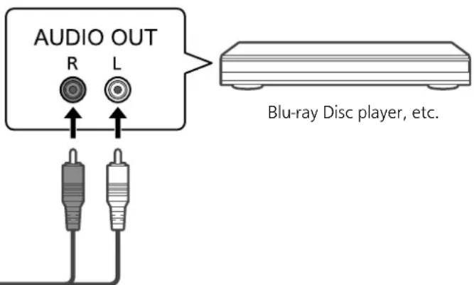
Using analog audio output device (PHONO/LINE1/LINE2)
text_image
You can connect the turntable with PHONO cable (not supplied) or the Blu-ray Disc player, etc. with analog audio cable (not supplied) to this unit and play back music. Turntable PHONO R L PHONO EARTH PHONO earth lead (not supplied) UPDATE 5V 500 mA CONTROL PC OPT2 OPT1 COAX2 COAX1 DIGITAL IN PHONO EARTH PHONO LINE OUT ANALOG (SOURCE ONLY) LINE 2 MAIN IN LINE 1 PRE OUT ANALOG INPHONO cable (not supplied)
Using PHONO cable/ analog audio cable
1 Disconnect the AC power supply cord.
2 Connect this unit and a device.
• PHONO terminals for connecting the turntable supports MM/MC type cartridge.
3 Connect the AC power supply cord to this unit. ( 13)
4 Press [AM∅] to turn this unit on.
5 Press [>INPUT<] repeatedly to select "PHONO", "LINE1" or "LINE2".
- You can also select the input source by turning the input selector knob on the unit.
- Set to "LINE2" ( 17) when "MAIN IN" is displayed as input source of this unit.
6 Start playback on the connected device.
Note
- When connecting a turntable with a built-in PHONO equalizer, turn the equalizer of turntable off or connect the PHONO cable to the analog audio input terminals (LINE1 or LINE2) of this unit.
- When connecting a turntable with a PHONO earth lead, connect the PHONO earth lead to the PHONO EARTH terminal of this unit.
Selecting the cartridge type
Select the settings (MM/MC) to fit the cartridge type of the connected turntable.
1 Press [AMP].
2 Press [MENU].
3 Press[], [▼] repeatedly to select "MM/MC" and then press [OK].
4 Press[], [▼] to select "MM"/"MC" and then press [OK].
Minimizing sound distortion
If sound distortion occurs when using the analog audio input terminals, setting the attenuator may improve the sound quality.
• The factory default is "Off".
1 Press [AMP].
2 Press [MENU].
3 Press[], [▼] repeatedly to select "Attenuator" and then press [OK].
4 Press[], [▼] to select a value and then press [OK].
- "Attenuator" settings can be stored for "MM" and "MC" individually.
text_image
SPEAKERS / HAUT-PARLEURS (4-16 Ω) Class 2 Wiring AC IN ~Analog audio cable (not supplied)
Do not input the audio signal from PRE OUT/LINE OUT terminals to the analog audio input terminals of this unit. Doing so may cause malfunction.
text_image
AUDIO OUT R L Blu-ray Disc player, etc.Reducing low frequency noise
Reduces the low frequency noise caused by the warpage of record.
• The factory default is "Off".
1 Press [AMP].
2 Press [MENU].
3 Press[], [▼] repeatedly to select "Subsonic Filter" and then press [OK].
4 Press[], [▼] to select "On" and then press [OK].
Switching a phase of record to play
Sets to play back and enjoy the inverted phase audio.
• The factory default is "Normal".
1 Press [AMP].
2 Press [MENU].
3 Press[], [▼] repeatedly to select "Phase" and then press [OK].
4 Press[], [▼] to select "Normal" / "Invert" and then press [OK].
- While setting to "Invert", the input source appears as inverted color on display.
- This function is not available for the audio output signal from LINE OUT terminals.
When connecting to "LINE2"
Analog audio input terminals (LINE2/MAIN IN) have both LINE2 and MAIN IN functions. When not in use as main amplifier, switch the input setting of this unit to "LINE2".
• The factory default is "LINE2".
1 Press [AMP].
2 Press [>INPUT<] repeatedly to select "MAIN IN".
3 Press [MENU].
4 Press[], [▼ repeatedly to select "Input Mode" and then press [OK].
5 Press[], [▼ repeatedly to select "LINE2" and then press [OK].
6 Confirm the displayed message and press [OK].
- The volume level set after switching to "LINE2" is displayed. Confirm and adjust the volume before pressing [OK].
7 Press [▲], [▼] to select "Yes" and then press [OK].
Operations
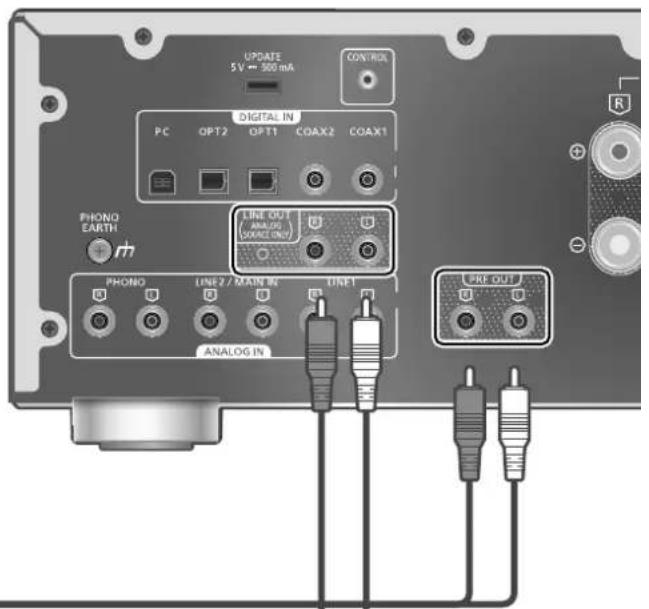
Using this unit as power amplifier
You can connect the AV receiver, control amplifier, etc. with analog audio cable (not supplied) to this unit and use this unit as power amplifier.
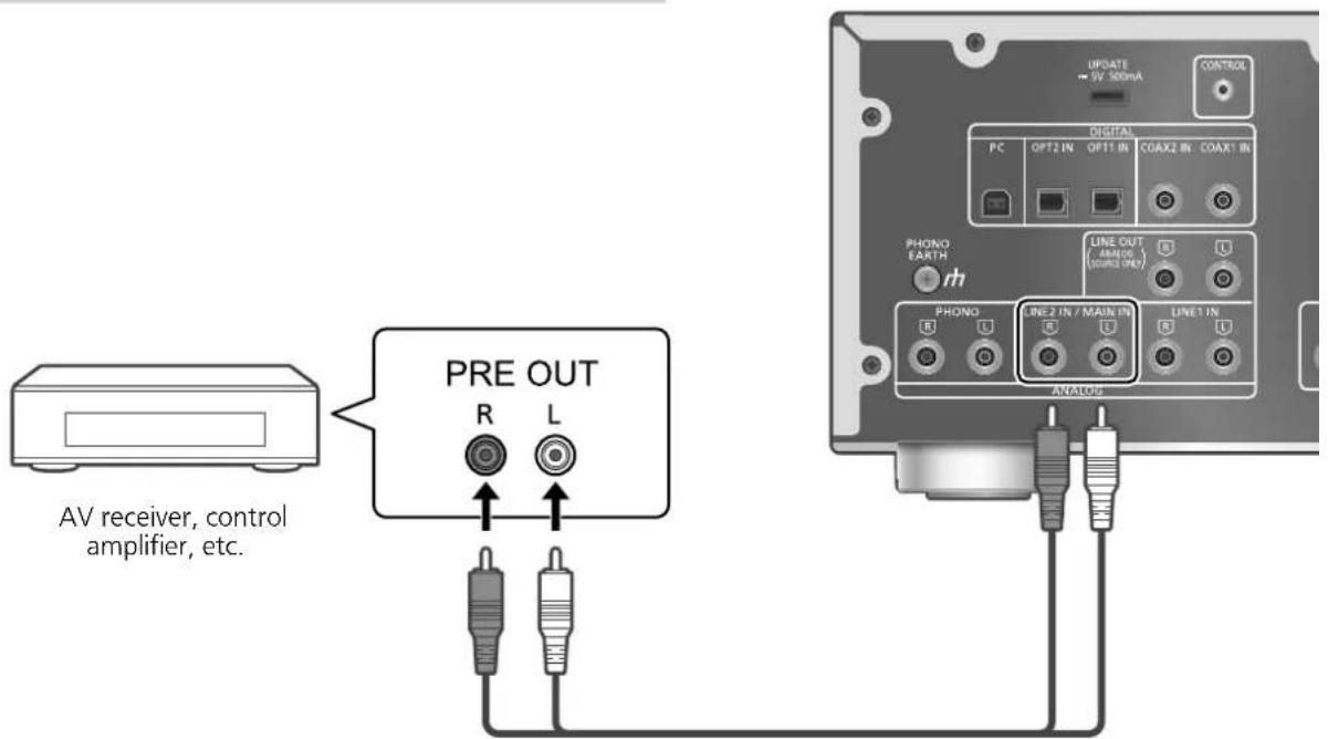
text_image
AV receiver, control amplifier, etc. PRE OUT R L UPATE - 5V 300mA CONTROL DIGITAL PC OPT2 IN OPT1 IN COAX2 IN COAX1 IN PHONO EARTH LINE OUT (AMINO) (SOUND ON) PHONO LINE2 IN / MAIN IN LINE1 IN ANALOGAnalog audio cable (not supplied)
Set the volume of the AV receiver, control amplifier, etc. to minimum before connecting.
While using this unit as power amplifier, the volume adjustment with this unit is disabled. Adjust the volume little by little with the connected device.
Do not input the audio signal from PRE OUT/LINE OUT terminals to the MAIN IN terminals of this unit. Doing so may cause malfunction.
Using analog audio cable
1 Disconnect the AC power supply cord.
2 Connect this unit and AV receiver, control amplifier, etc. after minimizing the volume of the device.
3 Connect the AC power supply cord to this unit. ( 13)
4 Press [AMF] to turn this unit on.
5 Press [>INPUT<] repeatedly to select "LINE2".
- You can also select the input source by turning the input selector knob on the unit.
6 Press [AMP].
7 Press [MENU].
8 Pres, [▼] repeatedly to select "Input Mode" and then press [OK].
9 Press], [▼] to select "MAIN IN" and press [OK].
text_image
SPEAKERS / HAUT-PARLEURS (4-16Ω) Class 2 Wiring PRE OUT AC IN ~10 Confirm the displayed message and press [OK].
11 Press [▲], [▼] to select "Yes" and then press [OK].
12 Start playback on the connected device.
Note
- It is not possible to adjust the volume and sound quality ("Tone Control", etc.) with this unit.
- Sound is not output from headphones jack and PRE OUT terminals.
- Select "LINE2" when not using this unit as power amplifier. (⇒ 17)
- When the input source is switched to "LINE2" or other source from "MAIN IN" and the current volume level is higher than previous level, the volume is automatically adjusted.
Minimizing sound distortion
If sound distortion occurs, setting the attenuator to "On" may improve the sound quality.
• The factory default is "Off".
1 Press [AMP].
2 Press [MENU].
3 Press[], [▼] repeatedly to select "Attenuator" and then press [OK].
4 Press[], [▼] to select "On" and then press [OK].
Operations
Connecting a power amplifier, subwoofer, etc.
You can connect the power amplifier, subwoofer, etc. with analog audio cable (not supplied) to output the analog audio signals.
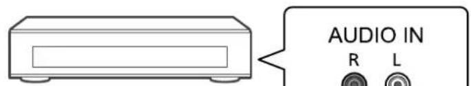
text_image
AUDIO IN R LPower amplifier, Subwoofer, etc.
text_image
UPDATE 5 V ↔ 500 mA CONTROL PC OPT2 OPT1 COAX2 COAX1 PHONO EARTH m LINE OUT (ANALOG (VACAO ONLY) PHONO LINE 2 / MAIN IN DINE1 ANALOG IN PRE OUTAnalog audio cable (not supplied)
Do not input the audio signal from PRE OUT/LINE OUT terminals to the analog audio input terminals of this unit. Doing so may cause malfunction.
Using analog audio cable
1 Disconnect the AC power supply cord.
2 Connect this unit and a power amplifier, subwoofer, etc.
3 Connect the AC power supply cord to this unit. ( 13)
4 Press [AM∅] to turn this unit on.
Note
- For details, refer to the operating instructions of the connected device.
- Sound is not output from PRE OUT terminals when using this unit as main amplifier. (⇒ 18)
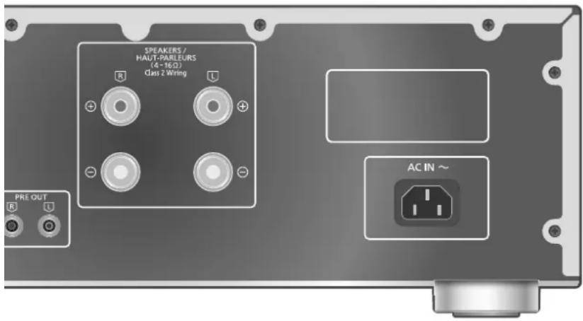
Setting the audio output (PRE OUT)
You can set the audio output of the speaker output terminals and PRE OUT terminals.
1 Press [AMP].
2 Press [SETUP].
3 Press[], [▼] repeatedly to select "PRE OUT" and then press [OK].
4 Press[], [▼] to select the output setting and then press [OK].
• The factory default is "Off".
- Not available when using this unit as main amplifier. (⇒ 18)
On:
Sound is output from the speaker output terminals and PRE OUT terminals.
On (Speaker:Off):
Sound is not output from the speaker output terminals. Sound is output from PRE OUT terminals.
Off:
Sound is not output from PRE OUT terminals. Sound is output from the speaker output terminals.
Note
- It is recommended to set to "On (Speaker:Off)" (rated output: 1 V) when connecting a power amplifier.
- Set to "Off" when using output correction function for the connected speakers because the correction function (LAPC) effects on the audio output from PRE OUT terminal. ( 24)
text_image
SPEAKERS / HALUT-PARLEURS (4-16 Ω) Class 2 Wiring AC IN ~You can connect the CD recorder, etc. with analog audio cable (not supplied) to output analog audio signals from this unit (LINE1/LINE2/PHONO).
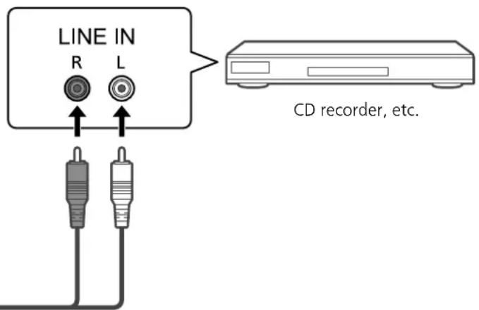
text_image
LINE IN R L CD recorder, etc.Analog audio cable (not supplied)
Do not input the audio signal from PRE OUT/LINE OUT terminals to the analog audio input terminals of this unit. Doing so may cause malfunction.
Using analog audio cable
1 Disconnect the AC power supply cord.
2 Connect this unit and a CD recorder, etc.
3 Connect the AC power supply cord to this unit. ( 13)
4 Press [AM∅] to turn this unit on.
Note
- When a digital audio signal (COAX1/COAX2/OPT1/OPT2/PC) is selected as input source of this unit, analog audio signal (LINE1) is output.
- The choppy audio occurs in output audio signal when switching the input source.
Settings
Sound adjustment, Other settings
The sound effects and other settings can be set up.
1 Press [AMP].
2 Press [SETUP].
3 Press▶, [▼ repeatedly to select the menu and then press [OK].
4 Press[], [], [ ] to select a desired item or value, and press [OK].
natural_image
Close-up of a white kitchen appliance with a circular knob and a rectangular door (no visible text or symbols)
natural_image
Illustration of a remote control with multiple buttons and a central knob (no text or symbols)Language setting "Language"
Select "English" or "Français" for the display. • The factory default is "English".
Adjusting BASS/MID/TREBLE "Tone Control"
You can adjust the tone of this unit. Each tonal range (BASS/MID/TREBLE) can be adjusted.
- To enable this function, select "On (adjustment)".
- The sound is temporary mute when switching "On (adjustment)" /"Off".
• Each level can be adjusted between "-10" and "+10".
• "TONE" is displayed after setting.
- While connecting Technics device supporting system control function (Network Audio Player, etc.) to this unit, sound setting on the connected device may have a priority over this unit. Adjust the sound with the connected device.
- Not available when using this unit as power amplifier (⇒ 18). Adjust the sound with the AV receiver, control amplifier, etc.
Adjusting balance of speakers "Balance L/R"
Adjusts the balance of the output from left and right speakers.
• Each level can be adjusted between 18 dB (L) and 18 dB (R).
• The audio output from the connected headphones and PRE OUT terminals are also adjusted.
- While using this unit as power amplifier ( 18), this setting is disabled. Adjust the setting with the connected device.
Adjusting the volume attenuator "VOLUME Attenuator"
Set to "On (-20dB)" for the attenuator to ease the volume adjustment at a low volume.
• The factory default is "Off".
- "ATT" is displayed and the volume level displays as -20 dB after setting. (Volume range: - dB (min), -98.0 dB to -20.0 dB (max))
- Not available when using this unit as power amplifier (⇒ 18). Adjust the sound with the AV receiver, control amplifier, etc.
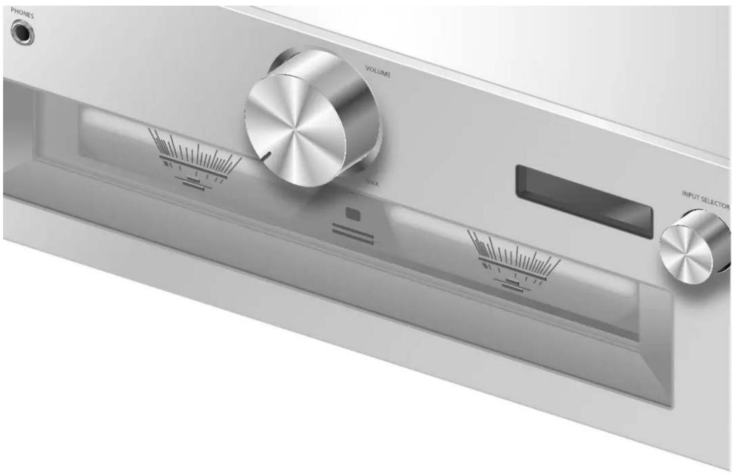
text_image
PHONES VOLUME MAX INPUT SELECTORAuto off function "Auto Off"
This unit is designed to conserve its power consumption and save energy. The unit has been left unused for about 20 minutes and will enter standby mode within a minute. Press any button to cancel it.
• The factory default is "Off".
- "Auto Off" is displayed 3 minutes before this unit is turned off.
Note
- The setting is stored even if the power is turned off and on.
Adjusting the dimmer level "Auto DIMMER"
The unit has been left unused for about 20 minutes and will temporarily adjust the brightness of peak power meter light, power indicator, LAPC indicator, etc.
• The factory default is "On".
- "Auto Off" function has a priority while "Auto Off" is set to "On".
Displaying the volume status "VOLUME Display"
The volume status is displayed when adjusting the volume.
• The factory default is "On".
- Not available when using this unit as main amplifier. (⇒ 18)
Checking the model name "Model No."
The model name is displayed.
Checking the firmware version "F/W Version"
The version of the installed firmware is displayed.
Settings
Using output correction function (LAPC)
You can make the optimum adjustment according to your own speakers.
Measuring the output signal of the amplifier and correcting its output (LAPC)
■ Preparation
- Disconnect the headphones.
Test tone emitted during measurement
To ensure the measurement accuracy, the speakers output a test tone at regular intervals. (For approximately 3 minutes) It is not possible to change the volume of the audio being output while the measurement is in progress.
1 Press [AMP ⏻] to turn this unit on.
2 Press and hold [LAPC] until "Please Wait" is displayed.
"LAPC Measuring" is displayed and this unit will start measuring the output signal of the amplifier. Check that a test tone is output from both the left and right speakers.
When the measurement is complete, amplifier output correction will be automatically turned on.
- The amplifier signal measurement is cancelled in the following condition.
- Pressing [MUTE]/[LAPC]
- Switching the input source
- If you connect headphones during amplifier signal measurement or amplifier output correction, it will be cancelled.
■ Turning on/off the output correction function
Press [LAPC] to select "On"/"Off".
- LAPC indicator lights and "LAPC : On" is displayed while the output correction function is in progress.
Note
- Set to "Off" when using output correction function for the connected speakers because the correction function (LAPC) effects on the audio output from PRE OUT terminal. ( 20)
- Depending on the type of the connected speakers, the effect of the output correction function may be minimal.
- The corrected output remains in effect until you measure the output signal again. When you use other speakers, redo the measurement.
Firmware updates
"F/W Update"
Occasionally, Panasonic may release updated firmware for this unit that may add or improve the way a feature operates. These updates are available free of charge.
- For the update information, refer to the following website.
www.technics.com/support/firmware/
Downloading takes approx. 5 minutes. Do not disconnect the AC power supply cord or turn this unit to standby while updating.
Do not disconnect the USB flash memory while updating.
- The progress is displayed as "Updating %" while updating. ("□" stands for a number.)
Note
- During the update process, no other operations can be performed.
- If there are no updates, "Firmware is Up To Date" is displayed. (No need to update it.)
- Updating the firmware may reset the settings of this unit.
■ Preparation
- Download the latest firmware on the USB flash memory. For details, refer to the following website.
www.technics.com/support/firmware/
1 Connect the USB flash memory with new firmware.
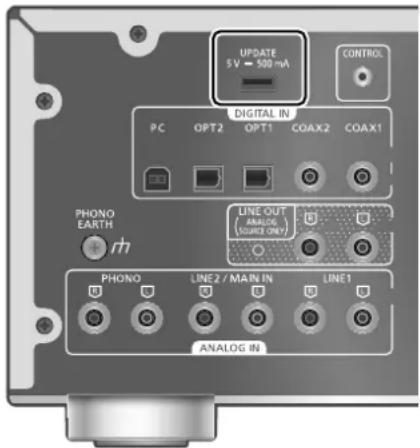
text_image
UPDATE 5 V - 500 mA CONTROL DIGITAL IN PC OPT2 OPT1 COAX2 COAX1 PHONO EARTH + rh LINE OUT ANALOG (SOURCE ONLY) PHONO LINE2 / MAIN IN LINE1 ANALOG IN2 Press [AMP].
3 Press [SETUP].
4 Press[], [▼] repeatedly to select "F/W Update" and then press [OK].
5 Press[], [▼] to select "Yes" and then press [OK].
- The progress is displayed as "Updating %" while updating. ("□" stands for a number.)
- When the update has finished successfully, "Success" is displayed.
6 After "Success" is displayed, press the standby/on button on this unit, disconnect the AC power supply cord and USB flash memory.
7 Reconnect the AC power supply cord after 3 minutes.
Note
- The update may have failed in the following cases.
- "Updating" is not displayed for 5 minutes or more.
- The progress display (\%) stops for 5 minutes or more In case of update failure, disconnect the AC power supply cord after turning this unit off, reconnect it after 3 minutes and update again with another USB flash memory.
- Downloading may take longer depending on the USB flash memory.
- Use a USB flash memory with FAT16 or FAT32 format.
- UPDATE terminal is used only for firmware updating. Do not connect any USB device other than the USB flash memory for firmware updating.
- No USB device can be charged from the UPDATE terminal of this unit.
Settings
System control connection
You can operate this unit and Technics devices supporting system control function (Network Audio Player, Compact Disc Player, etc.) simultaneously with ease on the remote control. For details, refer to the operating instructions of each device.
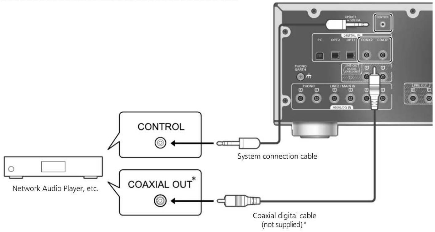
text_image
CONTROL COAXIAL OUT* System connection cable COAXIAL digital cable (not supplied)*Using system connection cable and audio cable
1 Disconnect the AC power supply cord.
2 Connect this unit and Technics device supporting system control function (Network Audio Player, etc.).
- Use both of the system connection cable and the audio cables when connecting this unit and the device.
- Use the system connection cable supplied with the connected device.
3 Connect the AC power supply cord to this unit. ( 13)
4 Press [AMP] to turn this unit on.
5 Press [AMP].
6 Press [SETUP].
7 Press[], [▼] repeatedly to select "System Control" and then press [OK].
8 Press [▲], [▼] to select the input source for the device which is connected at step 2, and press [OK].
- Select "Off" to disable the system control function.
*: The illustration shows the example when connecting with coax digital cable. Connect the device with proper cable/terminal supporting the device.
Note
- When using the system control function by connecting the Technics device to the LINE2 terminal of this unit, select "LINE2" (⇒ 17) for the input setting of the analog audio input terminals (LINE2/MAIN IN) of this unit.
- When using this unit as power amplifier (⇒ 18), the system control function for the Technics device connected to the MAIN IN terminals is disabled.
- The system control function is not available while "System Control" is set to "LINE2" and "Input Mode" is set to "MAIN IN" (⇒ 18) even when not in use as main amplifier.
text_image
SPEAKERS / HAUT-PARLEURS (4-16 Ω) Class 2 Wiring AC IN ~Switching this unit and the connected device
- If you point the remote control at this unit and press [AMP when this unit and the connected device are in standby mode, this unit and the device will be turned on simultaneously. -When the selected input source is same as the one which is set with "System Control"
- If you point the remote control at this unit and press [AMP Ⓑ] when this unit and the connected device are turned on, this unit and the connected device will enter standby mode.
- You can also switch this unit and the connected device by pressing the standby/on button on this unit.
Switching this unit's input source automatically
When you perform an operation such as playback on the connected device, the input source of this unit will be automatically switched to the source which is set with "System Control".
Before requesting service, make the following checks. If you are uncertain about some of the check points, or if the solutions indicated in the following guide do not resolve the issue, then consult your dealer for instructions.
Heat buildup of this unit
This unit becomes warm while in use. This is not a malfunction.
Do you have the latest firmware installed?
Panasonic is constantly improving the unit's firmware to ensure that our customers are enjoying the latest technology. (⇒ 25)
To restore all settings to the factory defaults
When the following situations occur, reset the memory:
- There is no response when buttons are pressed.
- You want to clear and reset the memory contents.
1 Press [AMP].
2 Press [SETUP].
3 Press[], [▼] repeatedly to select "Initialization" and then press [OK].
- A confirmation screen appears. Select "Yes" in the following steps to restore all the settings to defaults.
4 Press [▲], [▼] to select "Yes" and then press [OK].
5 Press[], [▼] to select "Yes" and then press [OK] again.
General
The unit does not work.
Operations are not done properly.
- One of the unit's safety devices may have been activated.
① Press [0/1] on the unit to switch the unit to standby.
- If the unit does not switch to standby, disconnect the AC power supply cord, wait for at least 3 minutes, then reconnect it.
② Press [0/1] on the unit to switch on. If the unit still cannot be operated, consult the dealer.
A "humming" sound can be heard during playback.
- An AC power supply cord of another device or fluorescent light is near the cables. Turn off other appliances, or keep them away from the cables of this unit.
- A strong magnetic field near a TV or other device may adversely affect the audio quality. Keep this unit away from such a location.
- The speakers may output noise when a device nearby is emitting powerful radio waves, such as when a mobile phone is on a call.
No sound.
- Check the volume of this unit and the connected device.
- Check connections to speakers and other equipment.
- Connect speakers and measure the output signal of the amplifier. (⇒ 24)
- Check the impedance of the connected speakers.
- Check to see if the correct input source is selected.
- Insert the plugs of the cables to be connected all the way in.
- Confirm the sound output setting. (Sound is not output from the speakers connected to the speaker output terminals of this unit while "PRE OUT" is set to "On (Speaker:Off)".) ( 20)
- Sound is not output from PRE OUT terminals while "PRE OUT" is set to "Off". (The factory default is "Off".) ( 20)
- When a plug is connected, the speakers and PRE OUT terminals do not output sound. ( 20)
- Playback of multi-channel content is not supported.
- The digital audio input terminals of this unit can only detect linear PCM signals. For details, refer to the operating instructions of the device.
Sound is distorted.
- Setting "Attenuator" to "On" according to the analog audio input may minimize the sound distortion. ( 16, 19)
- Setting the attenuator is not available for the output audio signal from LINE OUT terminal.
The volume is automatically changed.
- When the input source is switched to "LINE2" or other source from "MAIN IN" and the current volume level is higher than previous level, the volume is automatically adjusted. (Volume knob automatically turns.) ( 18)
The unit turns to standby mode automatically.
- Is the auto off function turned on? ( 23)
- This unit incorporates a protection circuit to prevent damage caused by heat buildup. When you use this unit at a high volume level for a long period of time, it may turn off automatically. Wait for this unit to cool down before turning on this unit again. (For approximately 3 minutes)
The settings are reset to the factory defaults.
- Updating the firmware may reset the settings.
The peak power meter does not operate.
- In the following cases, this meter does not operate:
- When the headphones are connected.
-When the peak power meter light is turned off by pressing [DIMMER]. - When this unit is muted by pressing [MUTE].
- When "PRE OUT" is set to "On (Speaker:Off)" ( 20)
The system control function is not working.
- Use the system connection cable supplied with the connected device.
- Connect the system connection cable to the system terminals (CONTROL). ( 26)
- Check the connection of system connection cable, audio cable and the input source which is set with "System Control". (⇒ 26)
- Connect Technics device supporting system control function (Network Audio Player, Compact Disc Player, etc.) to this unit. For details, refer to the following website.
www.technics.com/support/
PC
The PC does not recognize this unit.
- Check your operating environment. ( 15)
- Restart the PC, turn this unit to standby and on, and then reconnect the USB cable.
- Use another USB port of the connected PC.
- Install the dedicated USB driver if using a PC with Windows. (⇒ 15)
Remote control
The remote control does not work properly.
- The batteries are depleted or inserted incorrectly. ( 10)
- To avoid interference, please do not put any objects in front of signal sensor. ( 08)
- If the remote control mode of the remote control differs from that of this unit, match the mode of the remote control to the mode of this unit. ( 11)
Unit care
- Pull out the AC power supply cord from the outlet before maintenance. Clean this unit with a soft cloth.
- When dirt is heavy, wring a wet cloth tightly to wipe the dirt, and then wipe it with a soft cloth.
- Do not use solvents including benzine, thinner, alcohol, kitchen detergent, a chemical wiper, etc. This might cause the exterior case to be deformed or the coating to come off.
To dispose or transfer this unit
- This unit may contain private information. Before disposing of or transferring this unit, perform the following to delete the data, including personal or secret information.
- "To restore all settings to the factory defaults" ( 28)
Others
Troubleshooting (Continued)
Messages
ATTENTION : MAX Output Setting
- While using this unit as power amplifier, the volume adjustment with this unit is disabled.
- Adjust the volume little by little with the connected device. ( 18)
Auto Off
- The unit has been left unused for about 20 minutes and will shut down within a minute. Press any button to cancel it. ( 23)
Connect USB Device
• The firmware download has failed.
- Download the latest firmware on the USB flash memory and try again. (⇒ 25)
Disconnect PHONES
- When the headphones are connected, measuring the output signal of the amplifier (LAPC) will not start.
- Disconnect the headphones.
- If you connect headphones during amplifier signal measurement or amplifier output correction, it will be cancelled. (⇒ 24)
“F□□”(“□” stands for a number.)
- An abnormality has occurred. (If this unit detects an abnormality, the protection circuit is activated, and the power may be turned off automatically.)
- Is the volume extremely high? Or is this unit placed in an extremely hot place?
Wait a few seconds and then turn the unit on again. (The protection circuit will be deactivated.)
Load Fail
- The firmware cannot be found on the USB flash memory.
- Download the latest firmware on the USB flash memory and try again. ( 25)
No Device
- USB flash memory with new firmware is not connected.
Connect the USB flash memory with new firmware. ( 25)
Not Measured
- Measuring the output signal for the output correction function (LAPC) has not been done yet.
• Measure the output signal. (⇒ 24)
Not Valid
- The function you have tried to use is not available with the current settings. Check the steps and settings.
PHONES Connected
• The headphones are connected.
- Sound is not output from headphones jack and speaker output terminals when the headphones are connected and this unit is used as main amplifier. (⇒ 18)
- The remote control and this unit are using different modes.
Change the mode on the remote control. (⇒ 11)
"Remote□" ("□ stands for a number.)
Unlocked
- "COAX1", "COAX2", "OPT1", "OPT2" or "PC" is selected, but no device is connected. Check the connection with the device. (⇒ 14, 15)
- The sampling frequency components, etc. of the audio signals are not input correctly.
- About supported format, refer to "Specifications". (⇒ 31)
USB Over Current
USB device is drawing too much power.
- Disconnect the USB device and connect it again. (⇒ 25)
- Turn the unit to standby and on again.
VOLUME□□ OK ("□" stands for a number.)
- When the input source is switched to "LINE2" or other source from "MAIN IN", the volume level after switching the input source is displayed.
- Confirm and adjust the volume before pressing [OK].
GENERAL
| Power supply AC 120 V, 60 Hz | |
| Power consumption | 95 W |
| Power consumption in standby mode | Approx. 0.5 W |
| Dimensions (W×H×D) | 430 mm × 148 mm × 428 mm(16 ^15/_16 " × 5 ^13/_16 " × 16 ^27/_32 ") |
| Mass | Approx. 12.7 kg (28 lbs) |
| Operating temperature range | 0 °C to 40 °C(+32 °F to +104 °F) |
| Operating humidity range | 35 % to 80 % RH(no condensation) |
■ AMPLIFIER SECTION
| Output power | 70 W + 70 W(1 kHz, T.H.D. 0.5 %, 8 Ω,20 kHz LPF)140 W + 140 W(1 kHz, T.H.D. 0.5 %, 4 Ω,20 kHz LPF) |
| Load impedance | 4 Ω - 16 Ω |
| Frequency response | |
| PHONO (MM/MC) | 20 Hz to 20 kHz(RIAA DEVIATION ±1 dB,8 Ω) |
| LINE | 5 Hz to 80 kHz(-3 dB, 8 Ω) |
| DIGITAL | 5 Hz to 90 kHz(-3 dB, 8 Ω) |
| Input sensitivity/Input impedance | |
| PHONO (MM) | 2.5 mV / 47 kΩ |
| PHONO (MC) | 300 uV / 100 Ω |
| LINE | 200 mV / 22 kΩ |
■ TERMINALS SECTION
| Headphones Jack | Stereo, 6.3 mm (1/4") 0.75 mW, 32 Ω |
| PC | REAR USBType B Connector |
| Analog input | LINE IN ×2 (Pin Jack)PHONO (MM/MC),(Pin Jack) |
| Digital input | OPT IN ×2(Optical terminal)COAX IN ×2 (Pin Jack) |
| Format support | LPCM |
| Analog output | LINE OUT (Pin Jack)PRE OUT (Pin Jack) |
| System port | |
| System control | 3.5 mm (1/8"), Jack |
■ FORMAT SECTION
USB-B
| USB Standard | USB 2.0 high-speedUSB Audio Class 2.0, Asynchronous mode |
| Format support | |
| PCM | 32, 44.1, 48, 88.2, 96, 176.4, 192, 352.8, 384 kHz/16, 24, 32 bit |
| DSD | 2.8, 5.6, 11.2 MHz |
| DSD control mode | ASIO Native mode, DoP mode |
- If you download and install the dedicated app, you can play back files in wide-ranging formats. ( 15) For details, refer to the operating instructions of the app.
- Playback of all formats supported by this unit is not guaranteed.
- Playback of a format not supported by this unit may cause choppy audio or noise. In such cases, check to see if this unit supports the format.
- File information (sampling frequency, etc.) shown by this unit and playback software may differ from each other.
Note
- Specifications are subject to change without notice.
• Mass and dimensions are approximate.
• DSD is a trademark of Sony Corporation.
Technics Products - Limited Warranty
Limited Warranty Coverage
If your product does not work properly because of a defect in materials or workmanship, Panasonic Corporation of North America (referred to as "the warrantor") will, for the length of the period indicated on the chart below, which starts with the date of original purchase ("warranty period"), at its option either (a) repair your product with new or refurbished parts, (b) replace it with a new or a refurbished equivalent value product, or (c) refund your purchase price. The decision to repair, replace or refund will be made by the warrantor.
| Product or Part Name Parts | Labor | |
| Stereo Integrated Amplifier | 3 (three) years | 3 (three) years |
| Technics Music Server | ||
| Technics CD Stereo System | ||
| Technics Turntable System |
During the "Labor" warranty period there will be no charge for labor. During the "Parts" warranty period, there will be no charge for parts. This Limited Warranty excludes both parts and labor for non-rechargeable batteries, antennas, and cosmetic parts (cabinet). This warranty only applies to products purchased and serviced in the United States. This warranty is extended only to the original purchaser of a new product which was not sold "as is".
Mail-In Service--Online Repair Request
Online Repair Request
To submit a new repair request and for quick repair status visit our Web Site at
http://shop.panasonic.com/support
When shipping the unit, carefully pack, include all supplied accessories listed in the Owner's Manual, and send it prepaid, adequately insured and packed well in a carton box. When shipping Lithium Ion batteries please visit our Web Site at http://shop.panasonic.com/support as Panasonic is committed to providing the most up to date information. Include a letter detailing the complaint, a return address and provide a daytime phone number where you can be reached. A valid registered receipt is required under the Limited Warranty.
IF REPAIR IS NEEDED DURING THE WARRANTY PERIOD, THE PURCHASER WILL BE REQUIRED TO FURNISH A SALES RECEIPT/PROOF OF PURCHASE INDICATING DATE OF PURCHASE, AMOUNT PAID AND PLACE OF PURCHASE. CUSTOMER WILL BE CHARGED FOR THE REPAIR OF ANY UNIT RECEIVED WITHOUT SUCH PROOF OF PURCHASE.
Limited Warranty Limits and Exclusions
This warranty ONLY COVERS failures due to defects in materials or workmanship, and DOES NOT COVER normal wear and tear or cosmetic damage. The warranty ALSO DOES NOT COVER damages which occurred in shipment, or failures which are caused by products not supplied by the warrantor, or failures which result from accidents, misuse, abuse, neglect, mishandling, misapplication, alteration, faulty installation, set-up adjustments, misadjustment of consumer controls, improper maintenance, power line surge, lightning damage, modification, introduction of sand, humidity or liquids, commercial use such as hotel, office, restaurant, or other business or rental use of the product, or service by anyone other than a Factory Service Center or other Authorized Servicer, or damage that is attributable to acts of God.
| The model number and serial number of this product can be found on either the back or the bottom of the unit.Please note them in the space provided below and keep for future reference. | |
| MODEL NUMBER | SU-G700M2 |
| SERIAL NUMBER | |
THERE ARE NO EXPRESS WARRANTIES EXCEPT AS LISTED UNDER "LIMITED WARRANTY COVERAGE".
THE WARRANTOR IS NOT LIABLE FOR INCIDENTAL OR CONSEQUENTIAL DAMAGES RESULTING FROM THE USE OF THIS PRODUCT, OR ARISING OUT OF ANY BREACH OF THIS WARRANTY.
(As examples, this excludes damages for lost time, travel to and from the servicer, loss of or damage to media or images, data or other memory or recorded content. The items listed are not exclusive, but for illustration only.)
ALL EXPRESS AND IMPLIED WARRANTIES, INCLUDING THE WARRANTY OF MERCHANTABILITY, ARE LIMITED TO THE PERIOD OF THE LIMITED WARRANTY.
Some states do not allow the exclusion or limitation of incidental or consequential damages, or limitations on how long an implied warranty lasts, so the exclusions may not apply to you.
This warranty gives you specific legal rights and you may also have other rights which vary from state to state. If a problem with this product develops during or after the warranty period, you may contact your dealer or Service Center. If the problem is not handled to your satisfaction, then write to:
Panasonic Corporation of North America
Consumer Affairs Department 8th Fl.
Two Riverfront Plaza
Newark NJ 07102-5490
PARTS AND SERVICE, WHICH ARE NOT COVERED BY THIS LIMITED WARRANTY, ARE YOUR RESPONSIBILITY.
Shop Accessories!
for all your Technics gear
Go to
http://shop.panasonic.com/support
Get everything you need to get the most out of your Technics products
Accessories & Parts for your Camera, Phone, A/V products, TV, Computers & Networking, Personal Care, Home Appliances, Headphones, Batteries, Backup Chargers & more…
Customer Services Directory
For Product Information, Operating Assistance, Parts, Owner's Manuals, Dealer and Service info go to http://shop.panasonic.com/support
For the hearing or speech impaired TTY: 1-877-833-8855
As of December 2019
User memo:
| DATE OF PURCHASE | |
| DEALER NAME | |
| DEALER ADDRESS | |
| TELEPHONE NUMBER |
Panasonic Canada Inc.
5770 Ambler Drive, Mississauga, Ontario L4W 2T3
TECHNICS PRODUCT - LIMITED WARRANTY
Panasonic Canada Inc. warrants this product to be free from defects in material and workmanship under normal use and for a period as stated below from the date of original purchase agrees to, at its option either (a) repair your product with new or refurbished parts, (b) replace it with a new or a refurbished equivalent value product, or (c) refund your purchase price. The decision to repair, replace or refund will be made by Panasonic Canada Inc.
| Stereo Integrated Amplifier 3 (three) years parts and labour |
| Technics Music Server 3 (three) years parts and labour |
| Technics CD Stereo System 3 (three) years parts and labour |
| Technics Turntable System 3 (three) years parts and labour |
This warranty is given only to the original purchaser, or the person for whom it was purchased as a gift, of a Technics brand product mentioned above sold by an authorized Panasonic dealer in Canada and purchased and used in Canada, which product was not sold "as is", and which product was delivered to you in new condition in the original packaging.
IN ORDER TO BE ELIGIBLE TO RECEIVE WARRANTY SERVICE HEREUNDER, A PURCHASE RECEIPT OR OTHER PROOF OF DATE OF ORIGINAL PURCHASE, SHOWING AMOUNT PAID AND PLACE OF PURCHASE IS REQUIRED
LIMITATIONS AND EXCLUSIONS
This warranty ONLY COVERS failures due to defects in materials or workmanship, and DOES NOT COVER normal wear and tear or cosmetic damage. The warranty ALSO DOES NOT COVER damages which occurred in shipment, or failures which are caused by products not supplied by Panasonic Canada Inc., or failures which result from accidents, misuse, abuse, neglect, mishandling, misapplication, alteration, faulty installation, set-up adjustments, misadjustment of consumer controls, improper maintenance, power line surge, lightning damage, modification, introduction of sand, humidity or liquids, commercial use such as hotel, office, restaurant, or other business or rental use of the product, or service by anyone other than an Authorized Servicer, or damage that is attributable to acts of God.
Dry cell batteries are also excluded from coverage under this warranty.
THIS EXPRESS, LIMITED WARRANTY IS IN LIEU OF ALL OTHER WARRANTIES, EXPRESS OR IMPLIED, INCLUDING ANY IMPLIED WARRANTIES OF MERCHANTABILITY AND FITNESS FOR A PARTICULAR PURPOSE. IN NO EVENT WILL PANASONIC CANADA INC. BE LIABLE FOR ANY SPECIAL, INDIRECT OR CONSEQUENTIAL DAMAGES RESULTING FROM THE USE OF THIS PRODUCT OR ARISING OUT OF ANY BREACH OF ANY EXPRESS OR IMPLIED WARRANTY. (As examples, this warranty excludes damages for lost time, travel to and from the Authorized Servicer, loss of or damage to media or images, data or other memory or recorded content. This list of items is not exhaustive, but for illustration only.)
In certain instances, some jurisdictions do not allow the exclusion or limitation of incidental or consequential damages, or the exclusion of implied warranties, so the above limitations and exclusions may not be applicable. This warranty gives you specific legal rights and you may have other rights which vary depending on your province or territory.
WARRANTY SERVICE
For product operation, repairs and information assistance, please visit our Support page on:
http://panasonic.ca/english/support
IF YOU SHIP THE PRODUCT TO A SERVICENTRE
Carefully pack and send prepaid, adequately insured and preferably in the original carton. Include details of the defect claimed, and proof of date of original purchase.
text_image
Diagram showing a mechanical component with labeled parts and directional arrows indicating motion or movement.text_image
Diagram showing a lightning bolt symbol crossed out by two stacks of coins, indicating a signal or connection point.Câble PHONO (non fourni)
text_image
AUDIO IN R Lnatural_image
Close-up of a white appliance front panel with a circular knob and a rectangular cutout (no visible text or symbols)natural_image
Illustration of a remote control with buttons and a central knob (no text or symbols)Panasonic Canada Inc.
5770, Ambler Drive, Mississauga (Ontario) L4W 2T3
PRODUIT TECHNICS - GARANTIE LIMITÉE
Panasonic Corporation of North America
Two Riverfront Plaza, Newark, NJ 07102-5490
http://www.panasonic.com
Panasonic Canada Inc.
5770 Ambler Drive,
Mississauga, Ontario,
L4W 2T3
www.panasonic.com