
HAIF64IRB1S - Cooker HAIER - Free user manual and instructions
Find the device manual for free HAIF64IRB1S HAIER in PDF.
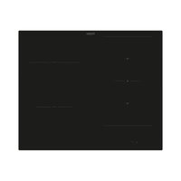


| Product type | Built-in induction hob |
| Brand | Haier |
| Model | HAIF64IRB1S |
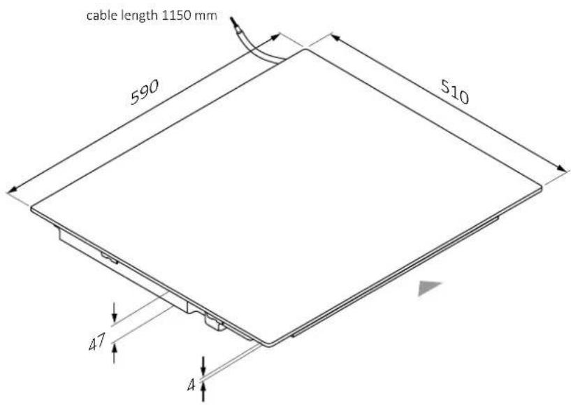
| Width | 59 cm |
| Depth | 51 cm |
| Height | 4.7 cm |
| Weight | Approximately 12 kg |
| Supply voltage | 220-240 V~ or 380-415 V~ 2N, 50/60 Hz |
| Maximum power consumption | 7.4 kW (adjustable from 2 to 7.4 kW) |
| Number of cooking zones | 4 induction zones |
| Control type | Touch slider control |
| Power management function | Yes, 8 power levels (P1 to P8) |
| Timer | Yes, built-in |
| Cleaning | Ceramic glass surface, clean with a soft cloth and specific cleaner |
| Safety | Child lock, automatic shut-off, overheat protection |
| Repairability index | Not communicated |
Frequently Asked Questions - HAIF64IRB1S HAIER
User questions about HAIF64IRB1S HAIER
0 question about this device. Answer the ones you know or ask your own.
Ask a new question about this device
Download the instructions for your Cooker in PDF format for free! Find your manual HAIF64IRB1S - HAIER and take your electronic device back in hand. On this page are published all the documents necessary for the use of your device. HAIF64IRB1S by HAIER.
USER MANUAL HAIF64IRB1S HAIER
WELCOME
This installation manual is designed for kitchen manufacturers who will deal with these products. To ensure safety and get the best results, please read this manual carefully, including the safety instructions, and keep it for future reference. Before proceeding with the installation, take note of the serial number, as you may need it in case of repairs. Check for any damage during transport and consult a technician when in doubt before using. Always keep all packing material away from children.
NOTE: Features, pictures in the manual and product accessories may vary depending on the model purchased.
Index
1 Safety warnings for installation p. 2
2 Where to install the product p.3
2.1 Other advice
3 Hob Dimensions p.4-9
3.1 Width 60 3.2 Width 65 3.3 Width 80
4 Installation tools p.10
4.1 Standard installation 4.2 Flush installation
5 Distance of installation p.11
5.1 Precautions
6 Furniture and ventilation p.12 - 13
6.1 Width 60 - 65 - 80 on oven base 6.2 Width 60 - 65 - 80 on base with drawers 6.3 Width 60 - 65 - 80 on base with shelves 6.4 Top thickness
7 Built-in dimensions p.14 - 19
7.1 Hob width 60 7.2 Hob width 65 7.3 Hob width 80
8 Connection to the mains p.20 - 22
8.1 Safety warnings 8.2 Instructions 8.3 Other advice 8.4 Layout of connection
9 Instructions for installation p.24 - 31
10.1 Important warnings 10.2 Step-by-step installation
11 Delivery to the user p.32
12 First startup p.32
13 Disassembling the product p.32
Observe these directions before beginning the installation of the product.
- Your safety is very important to us. Please read this information carefully before using the product;
- Installation must be carried on by a qualified technician who must know and respect the laws in force in the country of installation and the manufacturer's instructions;
- If the manufacturer service is required to eliminate faults resulting from improper installation, such service is not covered by the warranty;
- Remove the packing material before starting the appliance;
- After unboxing the appliance, carefully check there are no damages, in case of any issue contact the customer service before installing and do not connect to the power supply;
- A damaged product can be the cause of a short circuit, electrical shock, fire start and other hazards;
- Check the packaging for accessories or accompanying materials (documents, screws, accessory, brochure bag, user manual, etc.) remove and store them;
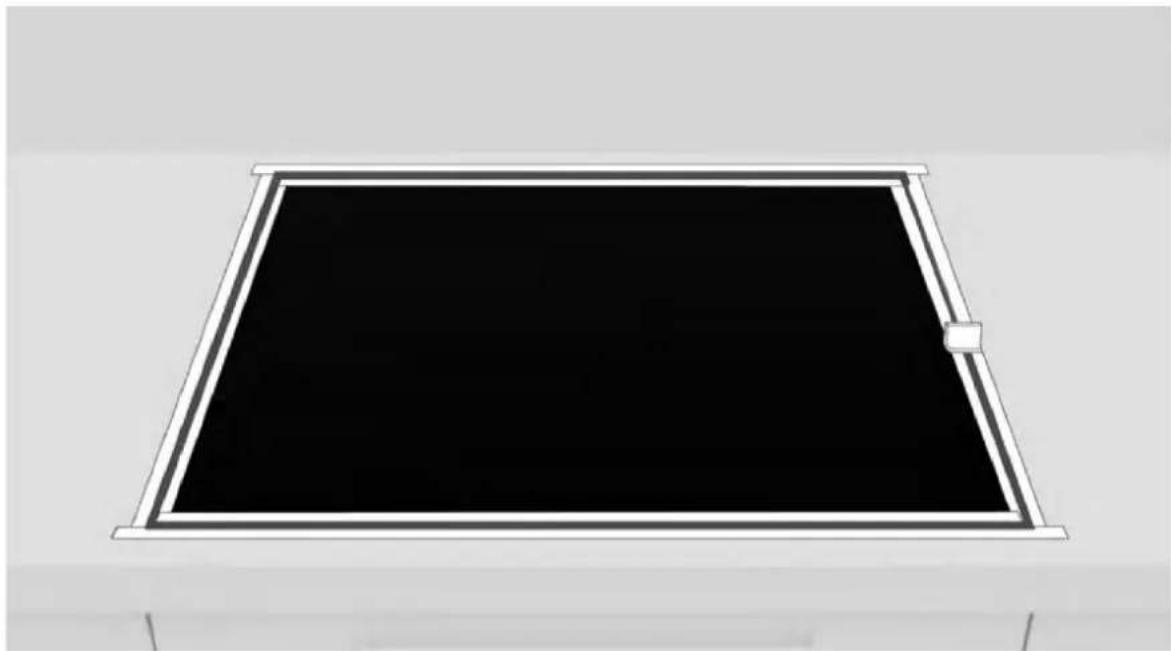
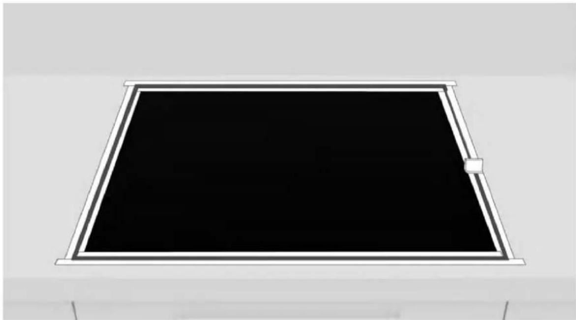
- The product can be installed in overlay or flush on the countertop;
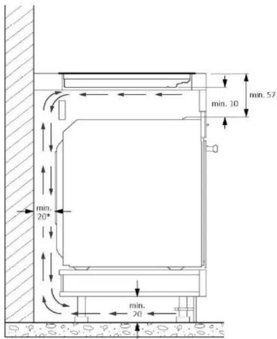
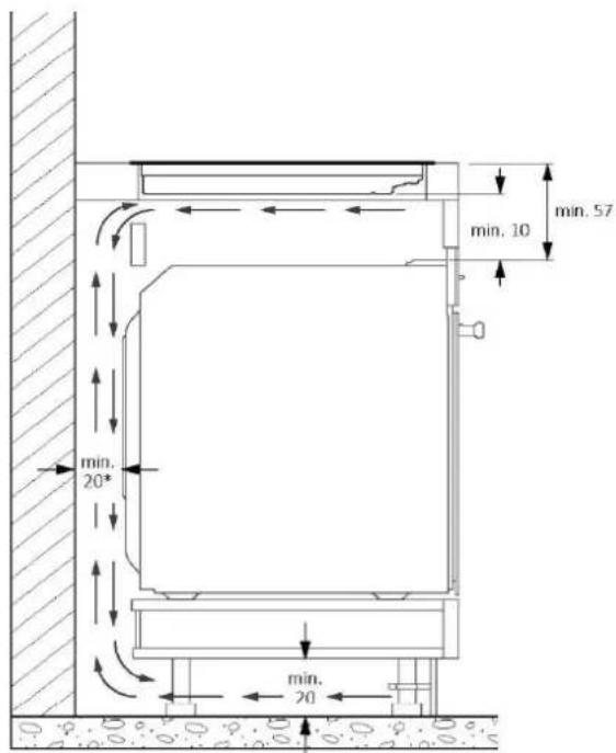
- Before installing the product, ensure the space is well-ventilated to allow circulation of fresh air, which is necessary for proper cooling. Follow the illustrations for minimum opening spaces suggested.
- No additional operation/setting is required in order to operate the appliance at the rated frequencies;
- If the assistance of the manufacturer is required to rectify faults arising from incorrect installation, this assistance is not covered by the warranty. The installation instructions for professionally qualified personnel must be followed;
- Incorrect installation may cause harm or injury to people, animals or belongings. The manufacturer cannot be held responsible for such harm or injury;
- Safe use is only guaranteed if installation has been carried out properly according to these instructions. In case of damage due to improper installation, the responsibility lies with the person who installed the product;
- During installation the hob should be disconnected from the mains;
- It is recommended to wear protective gloves during installation to avoid injuries;
- Warranty does not cover damage caused by improper installation;
- In case of incorrect installation, tampering with the device and improper connection, the validity of the product warranty will expire;
- Make sure that when the product's power supply cable is completed, it is not accessible;
- After assembly, the power cord must not come into contact with moving parts (such as a drawer) must not be exposed to mechanical stresses;
- This product requires constant ventilation during use. Do not cover the air vents.
- When delivering the product to the end user, the technician must ensure that it has been installed correctly.
Where to install the product
2
• Install and use this product in a closed, covered, dry, and well-ventilated environment. - Do not install the product in open environments exposed to atmospheric agents. - This appliance is designed to be used at altitudes lower than 2000m. • Install the product near an electrical outlet. - Use the product only when placed in a recessed compartment, otherwise you risk injury and burns. - Do not install the cooktop over an uncooled oven, dryer, dishwasher, or fridge. It is also recommended to avoid installation over a washing machine. Installation of the hob over a cooled oven is permitted.
2.1 Other tips
- Cut out the work surface precisely, using the tools needed depending on the material to be cut. All surfaces must be sealed or otherwise resistant to the penetration of humidity.
- The work surface must be shaped by following the diagrams in this manual. The cooking surface must be in a perfectly horizontal position. Check that the seal under the cooking surface, where provided, is properly placed.
- Use a soft cloth during installation to avoid damaging the cooktop and work surface.
⚠ WARNING: Danger of fire and damage from open flames. Keep open flames (e.g., a candle) away from the product.
3 Hob Dimensions
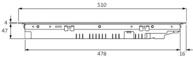
Width 603.1
Dimensions in mm
Top axonometric view
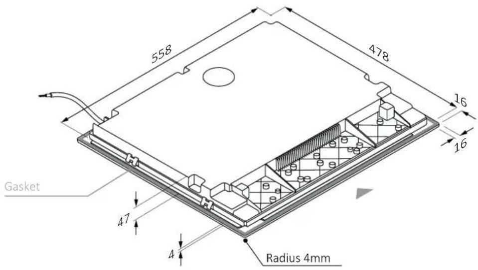
Lower axonometric view
3.1 Width 60
Dimensions in mm
Front view
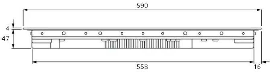
Side view
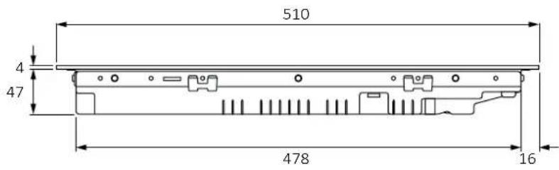
Product codes
HAIF64DCS
HAMT68IRB1S
HAMT66IRCS
HAIF64IRB1S
3 Hob Dimensions
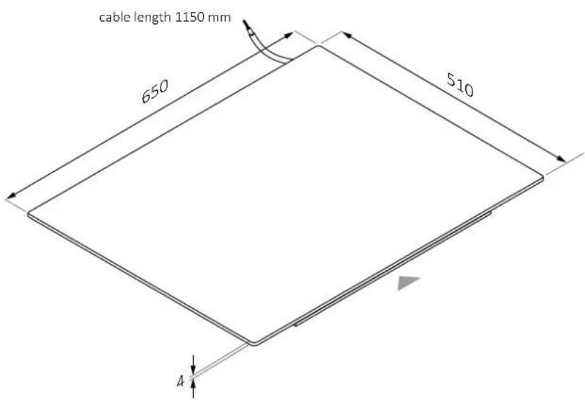
Width 653.2
Dimensions in mm
Top axonometric view
Lower axonometric view
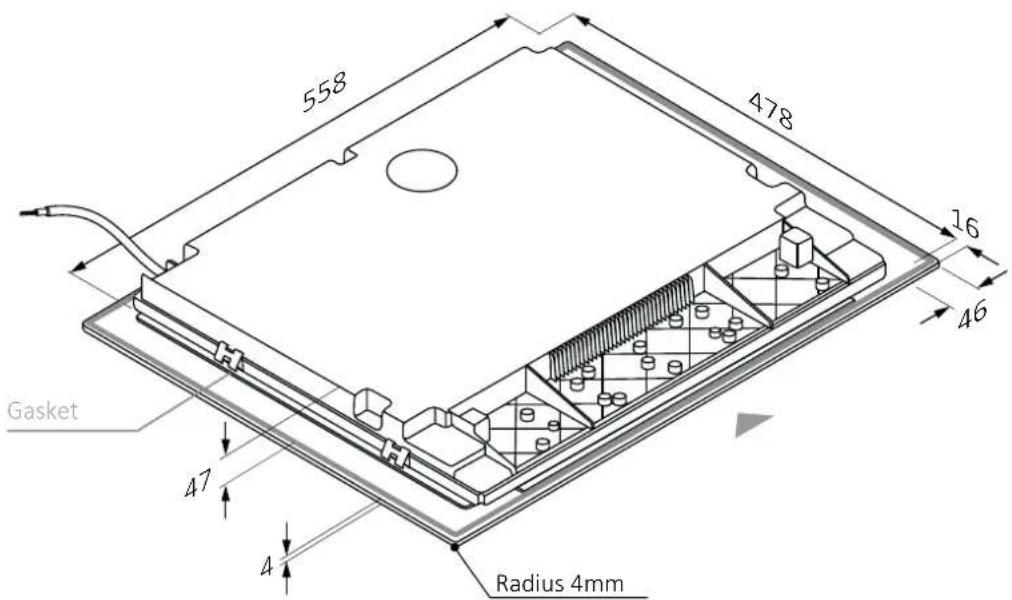
3.2 Width 65
Dimensions in mm
front view
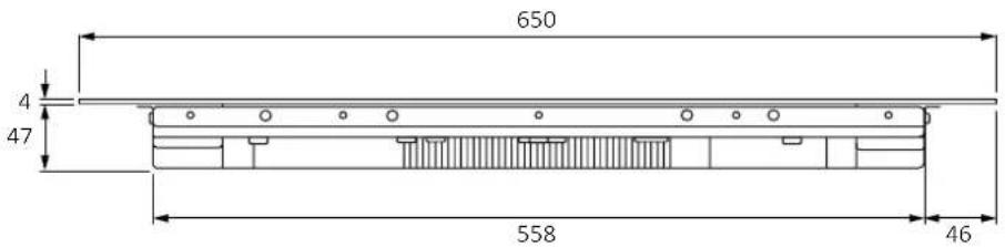
side view
Product codes
HAIFB54IRCS
HAIFB53IRCS
HAMTB56IRB1S
HA2MTB58IRB1S
HAMTB56IWCS
HAIFB54IWCS
HAIFB54CIRS
HA2MTB58IWB1S
HAIFB64TFTCS
3 Hob Dimensions
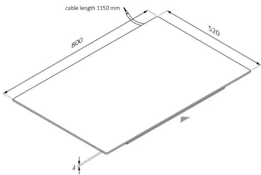
Width 803.3
Dimensions in mm
Top axonometric view
Lower axonometric view
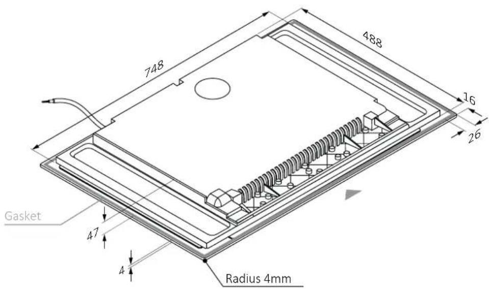
3.3 Width 80
Dimensions in mm
Front view
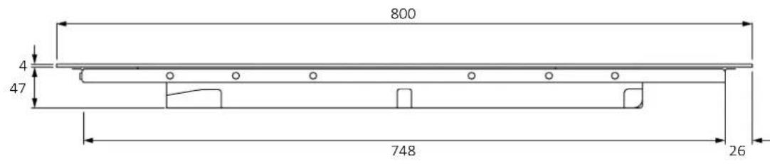
Side view
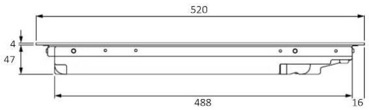
Product codes
HAMTB86IRCS
HAMTB86IWCS
4 Installation tools
Standard installation 4.1
Tools needed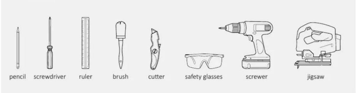
Tools provided with the product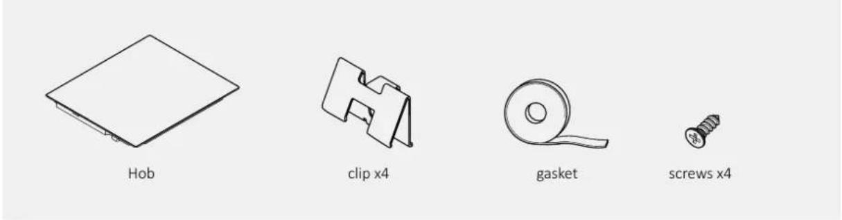
4.2 Flush installation
Tools needed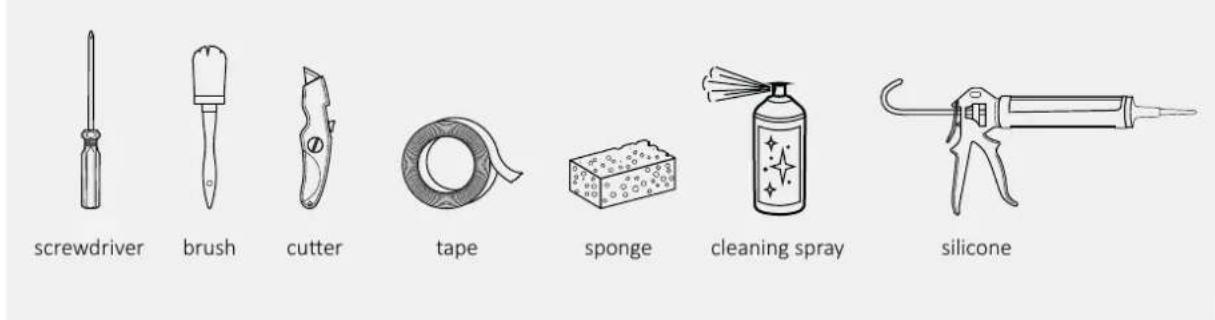
Tools provided with the product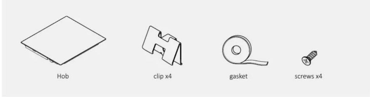
5.1 Precautions
- With regard to safety, this product complies with current regulations.
- The distance between the cooktop and the cabinets or recessed appliances should be such as to ensure sufficient ventilation and air release.
- The minimum distance between the hob and the hood depends on the model of the hood (A).
The distance between cooktop and wall cabinets should take into account the presence of bulky objects (pots, ladles, etc.), and their use (B).
The minimum distance between the hob hole and the kitchen back panel/back-splash should be at least 35 mm (C).
Maintain a safe side distance from the furniture (D). The side covering of the furniture should be made of heat-resistant material.
In the area below the hob it is necessary to have a free space of at least 10 mm between the hob and any other object, which could be affected by the heat generated during use.
Follow the instructions in this manual for ventilation of the product.
If the product is installed above an oven, also consult the oven installation instructions.
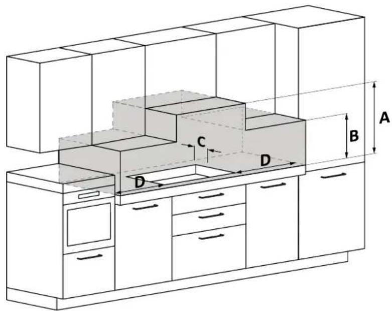
A: We recommend a distance of at least 650 mm, also consult the hood manual. B: Consider a useful space for handling pots, ladles and other items. C: 35 mm distance from the recessed hole to the back panel/backsplash. D: 35 mm for hob width 60; 55 mm for hob width 65; 35 mm for hob width 80.
6.1 Width 60 - 65 - 80 on oven base
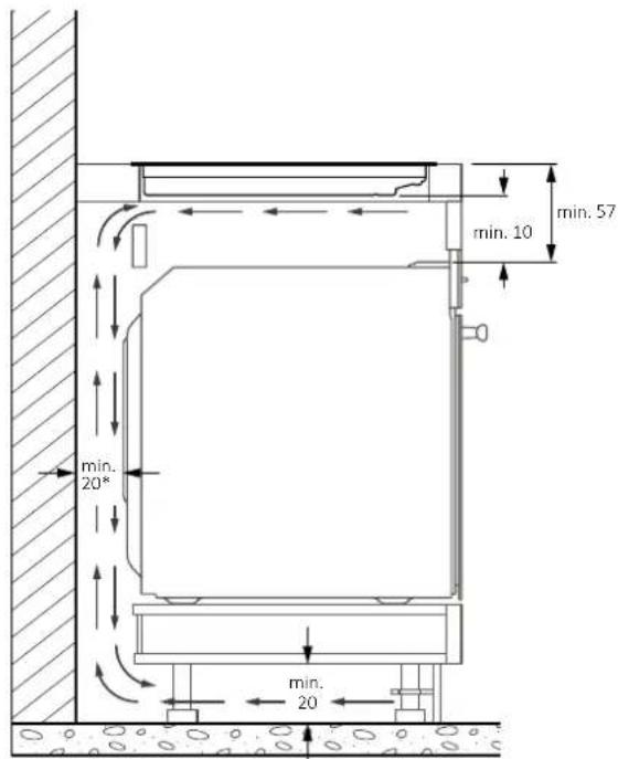
* Indication relating to the hob. For information relating to the oven, consult the dedicated installation manual.
6.2 Width 60 - 65 - 80 on base with drawers
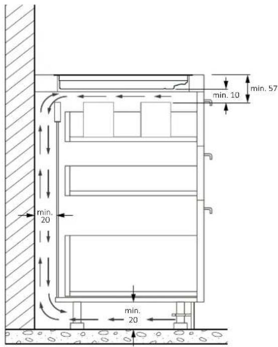
6.3 Width 60 - 65 - 80 on base with shelves
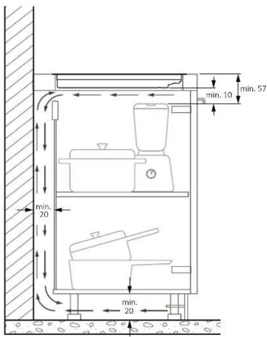
Furniture with thick countertop: provide a rear opening of at least 45mm between the top and the rear chain.
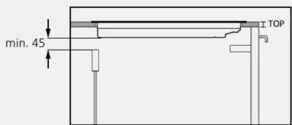
Furniture with reduced thickness countertop: provide a rear opening of at least 45mm between the cooktop and the rear chain.
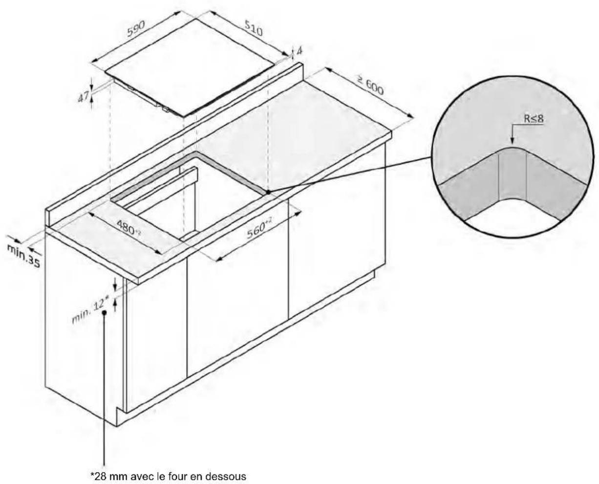
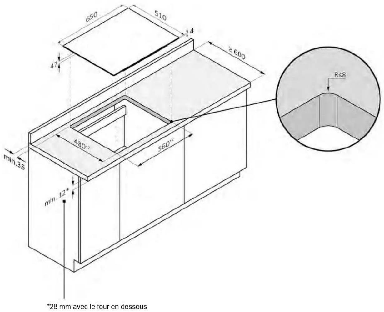
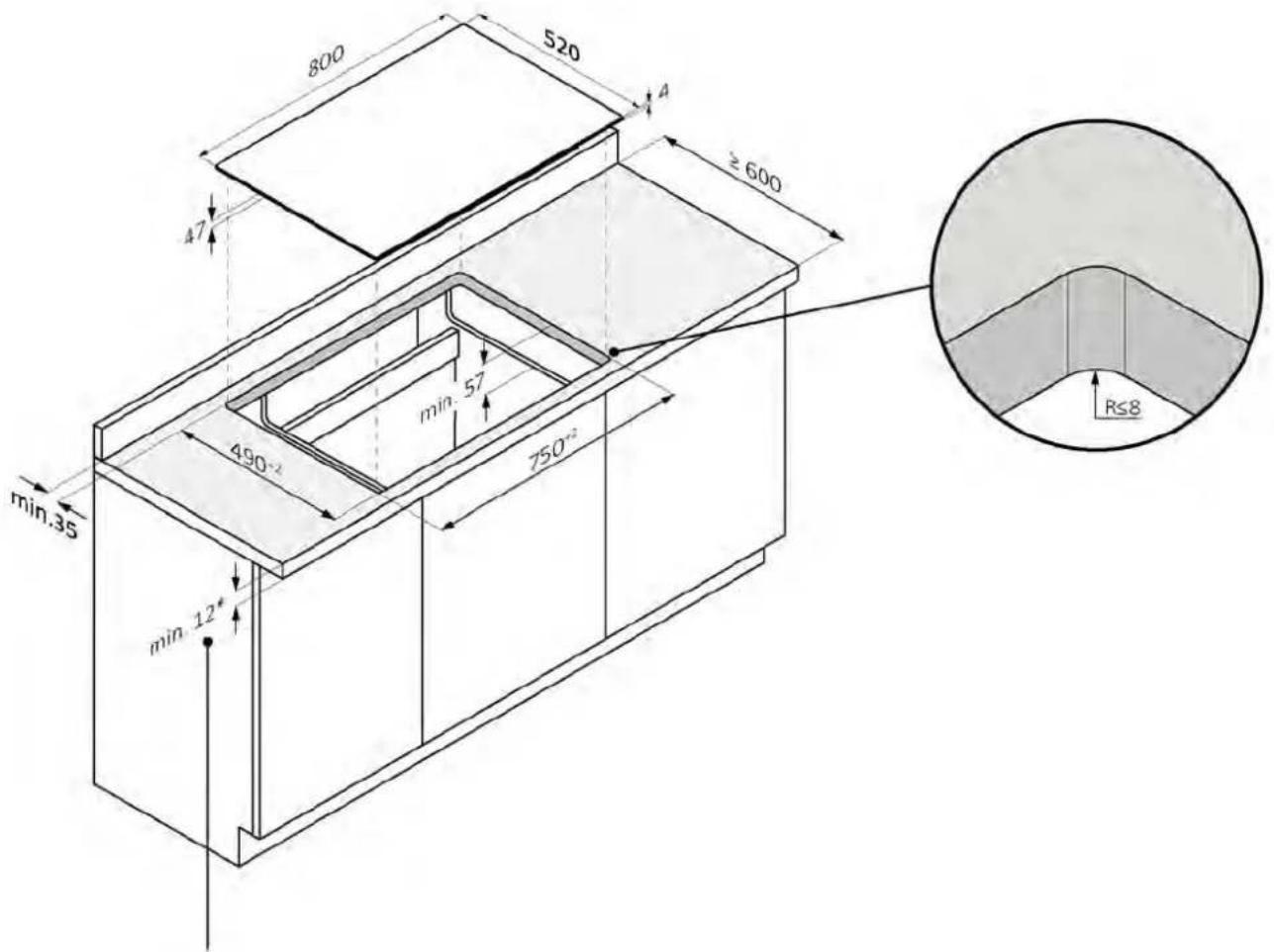
7 Built-in dimensions
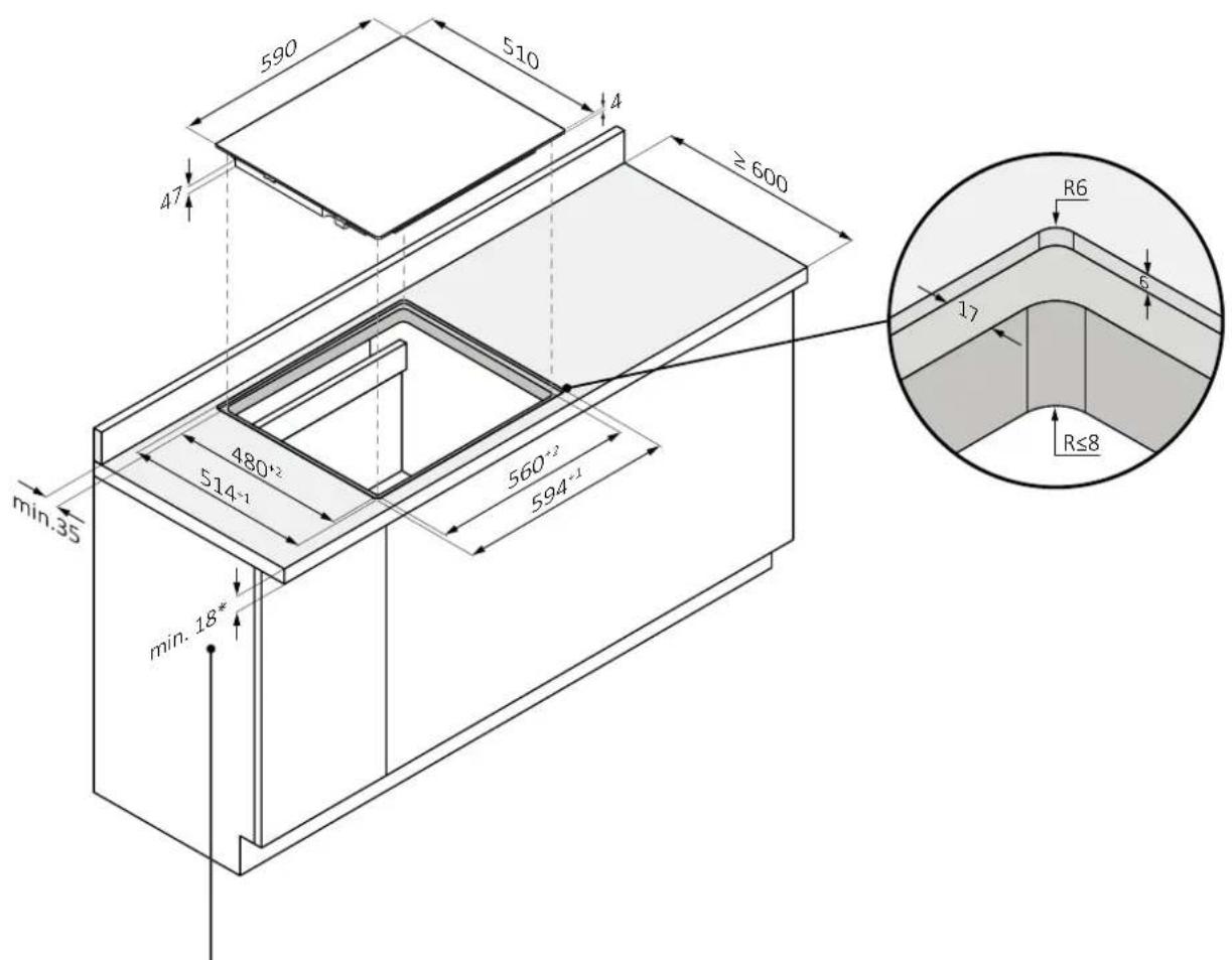
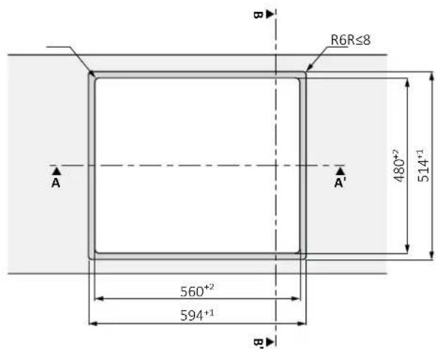
- The kitchen countertop should be shaped by following the diagrams below;
- The back of the cabinet should provide openings, follow the diagrams below.
7.1 Hob width 60
Standard installation
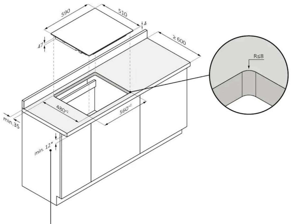
*28 with oven underneath
7.1 Hob width 60
Flush installation
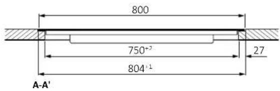
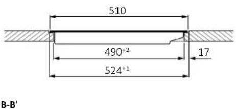
WARNING: Not available for products with beveled glass.
*28 with oven underneath
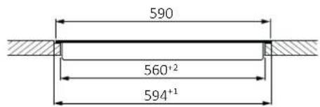
A-A'
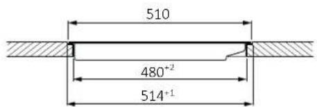
B-B'
7 Built-in dimensions
7.2 Hob width 65
Standard installation
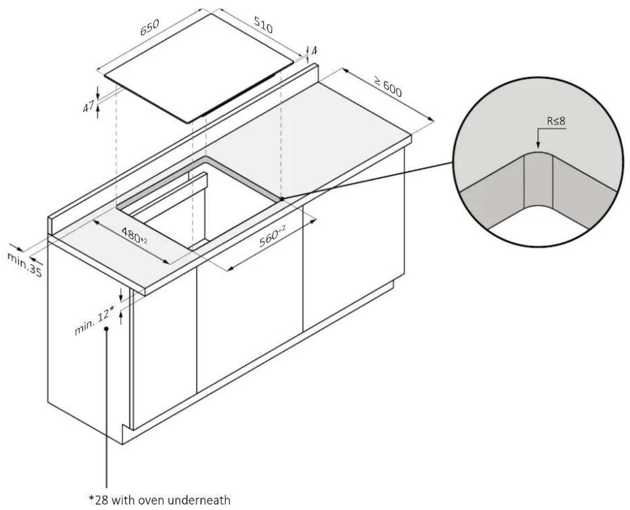
7.2 Hob width 65
Flush installation
⚠ WARNING: Not available for products with beveled glass.
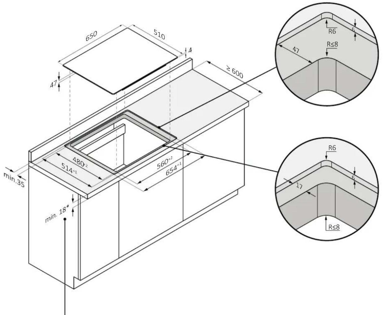
*34 with oven underneath
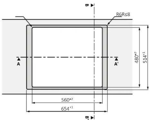
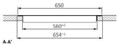
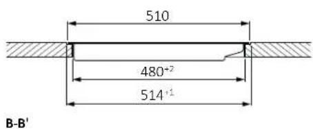
7 Built-in dimensions
7.3 Hob width 80
Standard installation
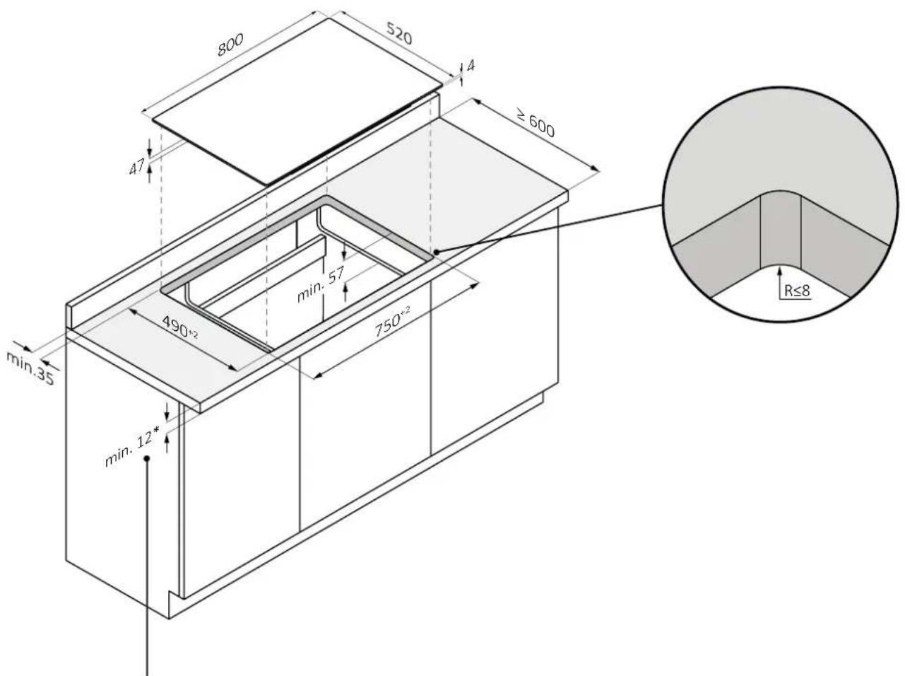
*28 with oven underneath
7.3 Hob width 80
Flush installation
WARNING: Not available for products with beveled glass.
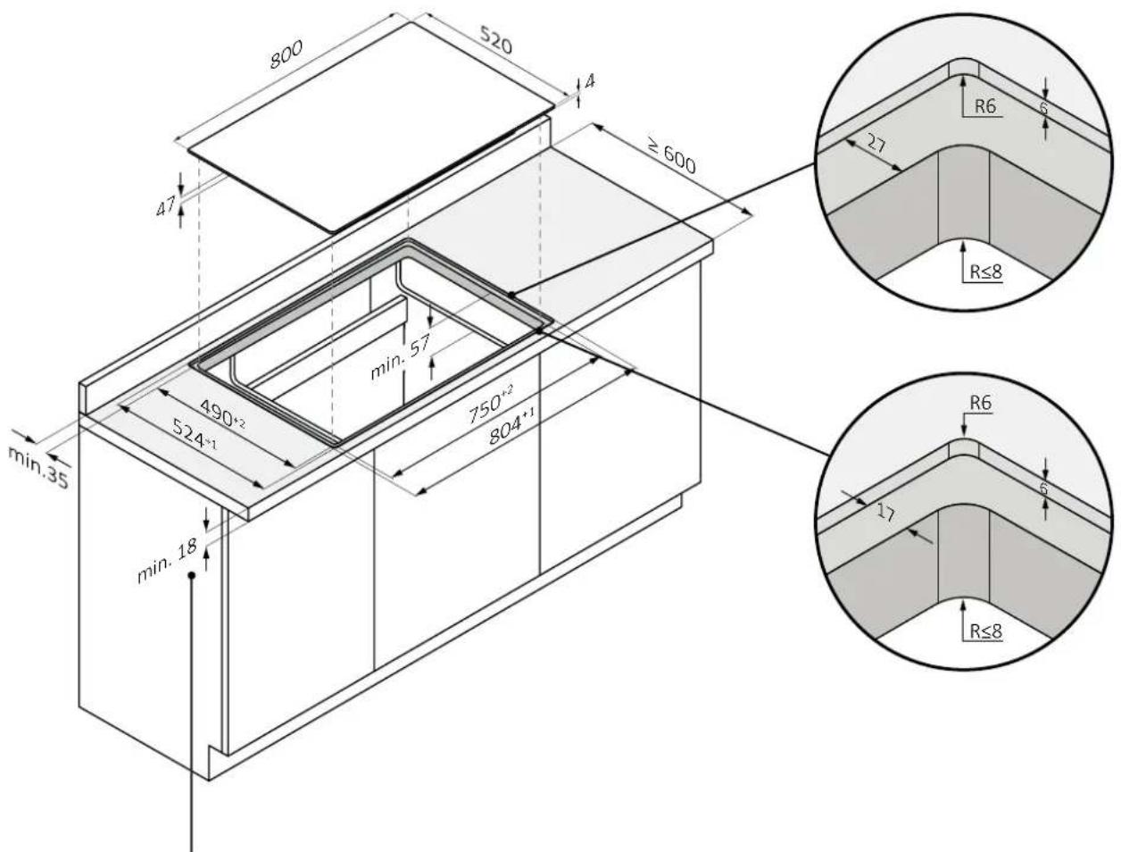
*34 with oven underneath
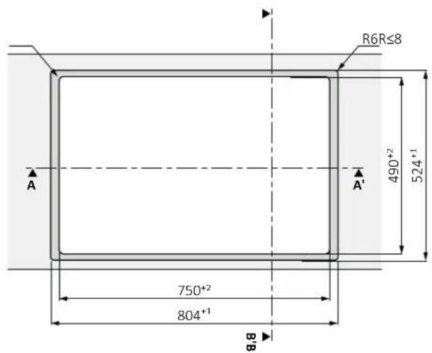
8.1 Safety warnings
To carry out the electrical connection of the device safely, observe the following warnings:
- Any improperly performed repair, installation and maintenance can seriously endanger the user;
- The producer declares that it assumes no liability for direct or indirect damage caused by incorrect installation, maintenance or repair. It is also not liable for damage caused by missing or interrupted grounding pipeline (electric shock);
- Have the hob connected to the power grid only by a qualified technician who knows and complies with local regulations and additional regulations of the local power company;
- The product falls under protection class I and can operate only if it is equipped with a grounding conductor;
- The product must be voltage-free during installation;
- During installation, do not place metal objects, (e.g., knives, forks, spoons and lids) on the surface of the cooktop because they may get hot;
- Connect the product using only the supplied cable;
- The product must be connected to a properly made electrical system;
- In case of incorrect installation, tampering with the device and improper connection, the validity of the product warranty will expire;
- If the power cord is damaged, it should be replaced by the manufacturer, a service technician or similarly qualified person to avoid risk;
- Connection to a reliable grounding system is essential and mandatory;
- This appliance should be installed and grounded only by a properly qualified person;
- Disconnect the appliance from the main power supply before doing any work or maintenance on it;
- This appliance must be connected to a circuit that incorporates an isolation switch that provides complete disconnection from the power source;
- Modifications to the home electrical system should be carried out only by a qualified electrician;
- Failure to follow these recommendations could result in electric shock or death;
- The hob must be connected to the power supply via an omnipolar disconnection device that ensures separation between contacts compliant with overvoltage category III. This device must withstand the maximum connected loads and comply with current regulations.
⚠ WARNING: To avoid any danger caused by accidental resetting of the thermal cutout device, the appliance must not be powered by an external switching device, such as a timer, or be connected to a circuit that is regularly switched on and off.
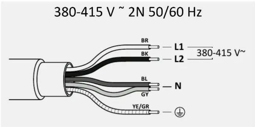
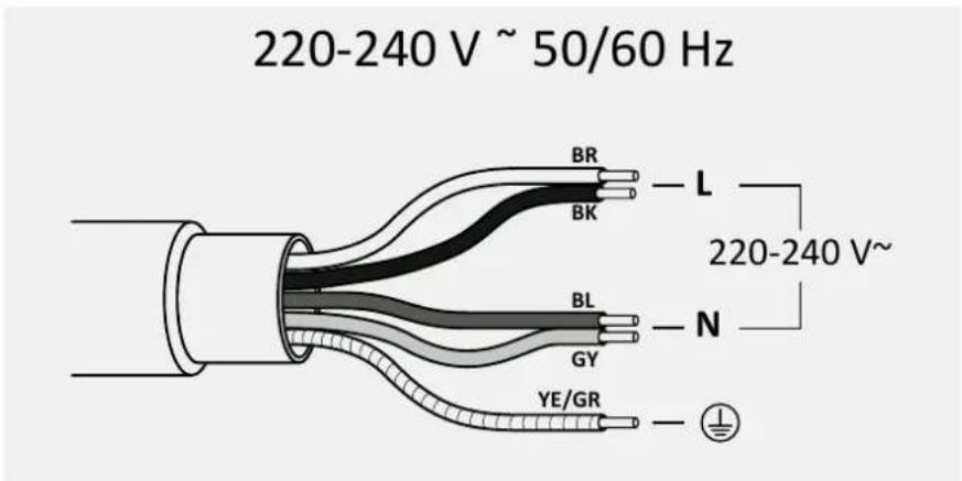
- Electrical power cable: the appliance is equipped with a power cable which must be connected to the home network. Find out the different connection possibilities, depending on the type of domestic power supply, from the relevant diagram. The data plate also indicates the connection voltage permitted for this appliance and the relative absorbed power.
8.2 Instructions
Power absorbed
See product data plate.
Differential circuit breaker (life-saving)
The use of a residual current circuit breaker (earth leakage circuit breaker) with trip current complying with current standards is recommended.
Separation devices
In the event that it is necessary to use it, the hob must be connected to the power supply via an omnipolar disconnection device that ensures a separation between contacts complying with overvoltage category III. Such a device must withstand the maximum loads connected and comply with current standards.
WARNING: To avoid any danger caused by accidentally resetting the thermal cut-off device, the appliance must not be powered by an external switching device, such as a timer, or be connected to a circuit that is regularly switched on and off. The product is not designed to be operated by an external timer or a separate remote control system.
Electrical power cable
The product is equipped with a power cable that must be connected to the home network. Find out the different connection possibilities, depending on the type of domestic power supply, from the relevant diagram. The data plate also indicates the permitted connection voltage for this appliance and the relative absorbed power.
Replacing the power cord
Do not replace the cable yourself. Contact the authorized assistance centre.
8.3 Other advice
The use of any household appliance requires adherence to certain basic rules:
- Do not pull the power cord to disconnect the appliance from the power supply;
- Do not touch the appliance with wet or damp hands or feet;
- In general, the use of adapters, power strips or extension cords is discouraged;
- In case of malfunction and/or drop in performance, turn off the appliance and do not tamper with it.
8.4 Connection diagram
Comply with local regulations and additional regulations of the local electrical company.
Connecting the appliance
Observe the connection data on the rating plate.
Carry out the connection exclusively in accordance with the relevant diagram:
- BR: brown
- BL: blue • YE/GN: yellow and green
- BK: black
- GY: grey
9.1 Important warnings
- Remove any possible transverse strips that are in the area of the worktop hole;
- For protection against humidity and the infiltration of liquids, all cut surfaces must be sealed with a suitable product; • The product must be in a perfect horizontal position; • Before installation, check that the hob gasket is positioned correctly (pic. 1).
pic. 1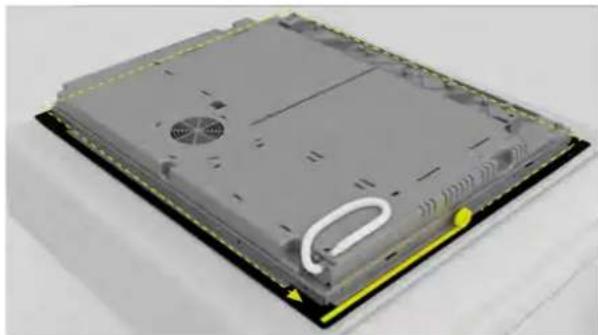
- The supporting surface of the cooktop must be perfectly smooth so that it rests evenly and the applied gasket can provide a sufficient seal (pic. 2).
pic. 2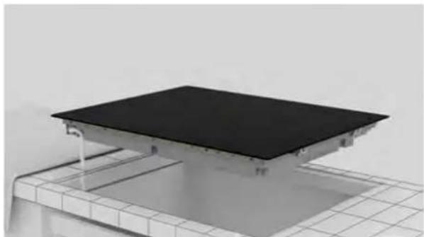
- Do not fix the cooktop by using silicone or any other adhesive! Such fixing would damage the product if you were to disassemble it (pic. 3).
pic. 3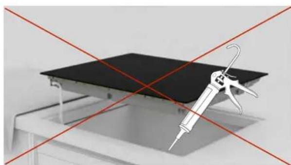
9.2 Step-by-step installation
The images below show the step-by-step installation of the product.
Standard installation
You can view the product installation video by scanning the QR code

or by clicking this link
Flush installation
You can view the product installation video by scanning the QR code

1
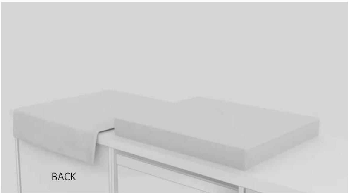
Engage the tools indicated in the "Installation Tools" chapter of the manual. Lay a cloth beside the product package to rest the hob on;
2
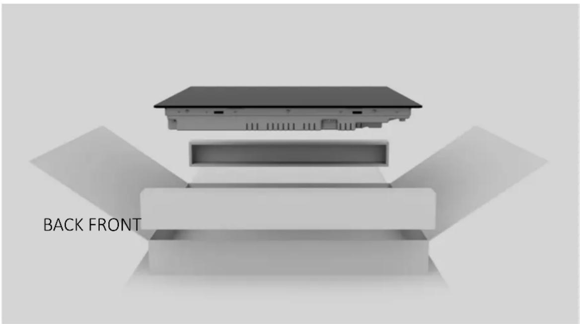
Wear gloves. Remove package and wrapping making sure not to damage the glass of the hob;
3
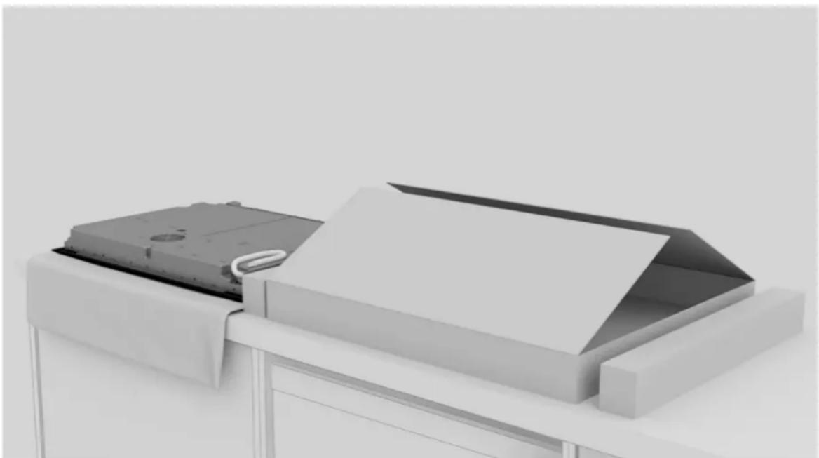
Place the hob by laying it upside down on the cloth previously laid beside the package;
9 Instructions for installation
4
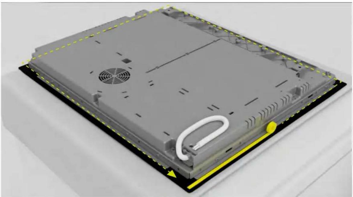
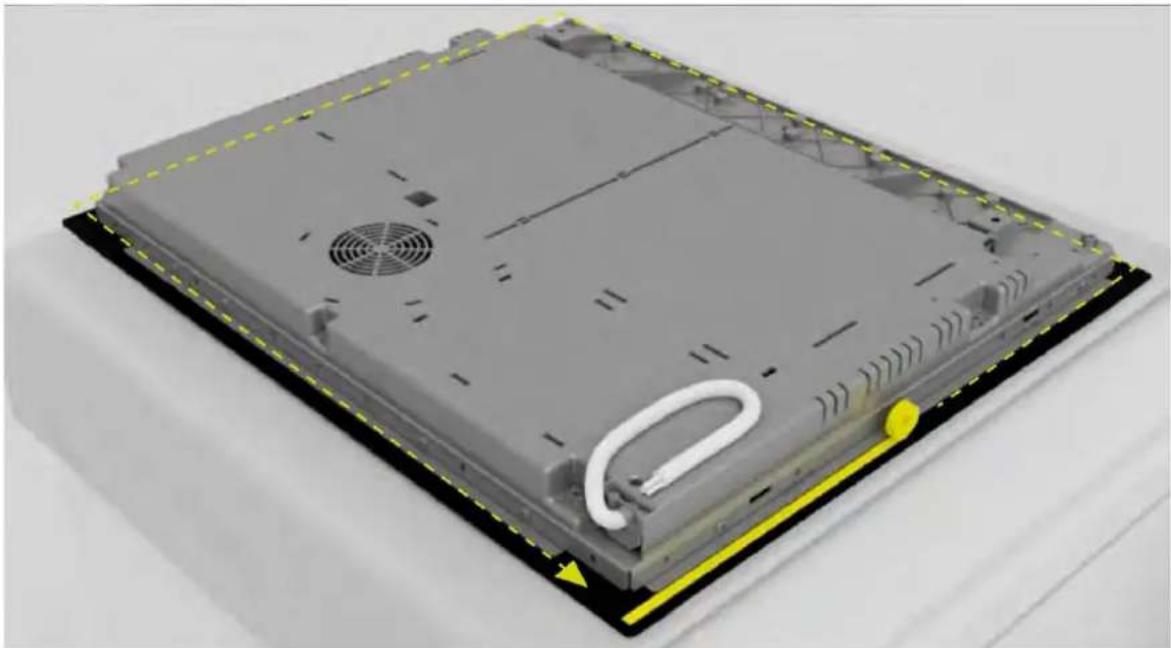
Apply gasket around the perimeter;
5
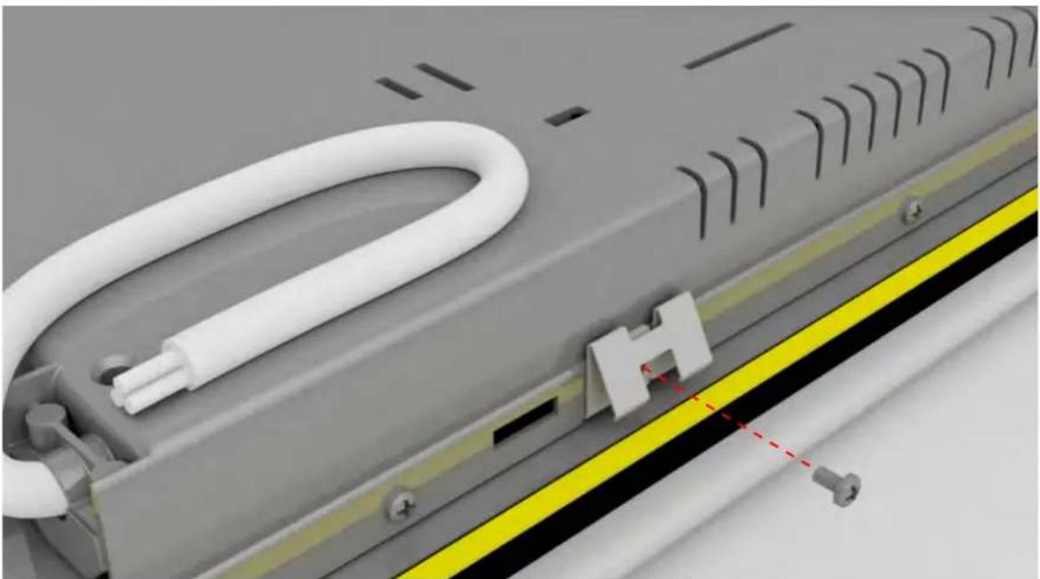
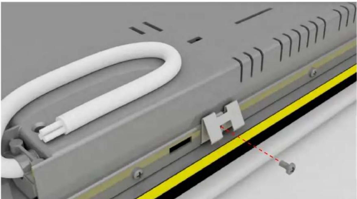
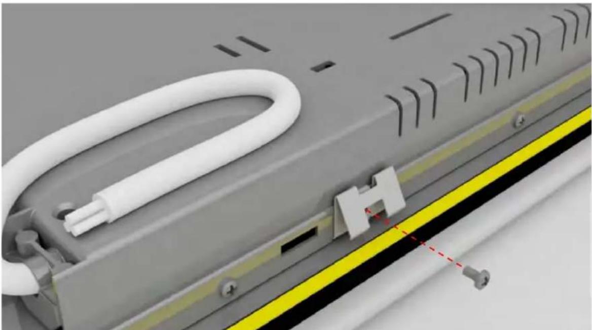
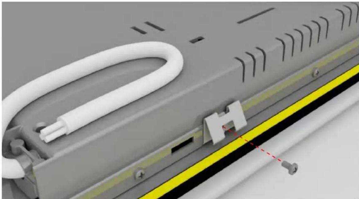
Attach the clips on the short sides of the hob;
6
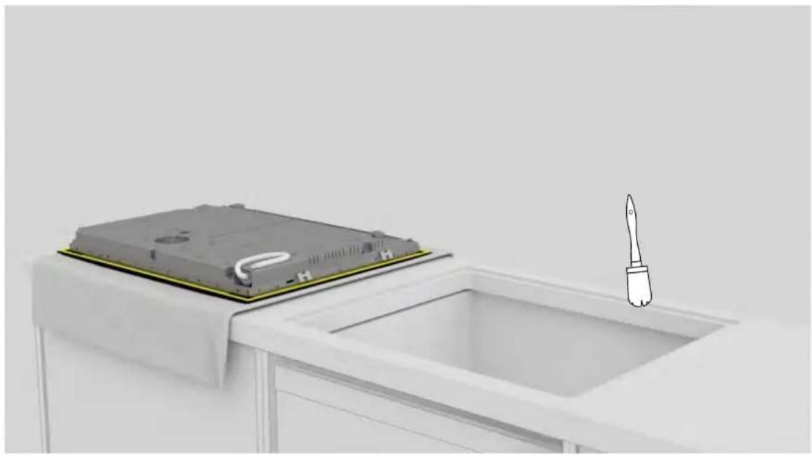
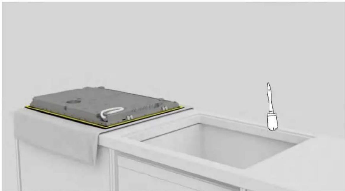
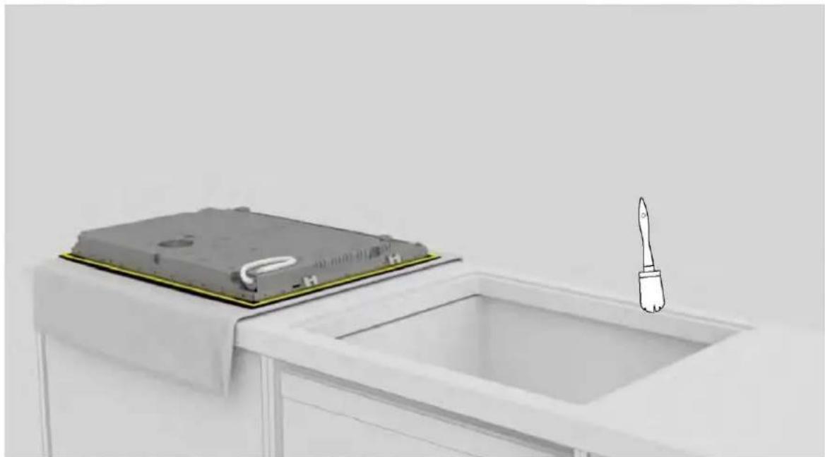
Clean the edge of the recessed area;
7
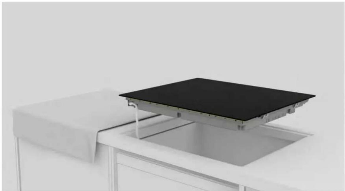
Connect the power supply cord according to the connection diagram shown in the “Mains Connection” section of the manual (no other objects should be on the hob during mains connection).
9 Instructions for installation
8
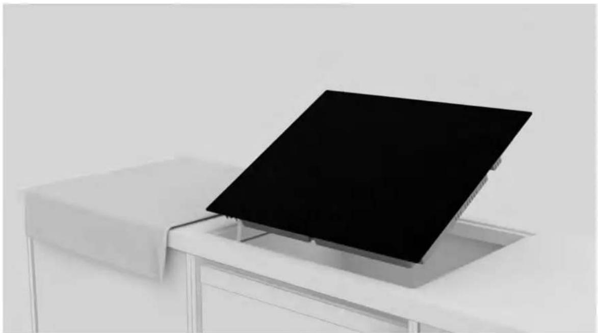
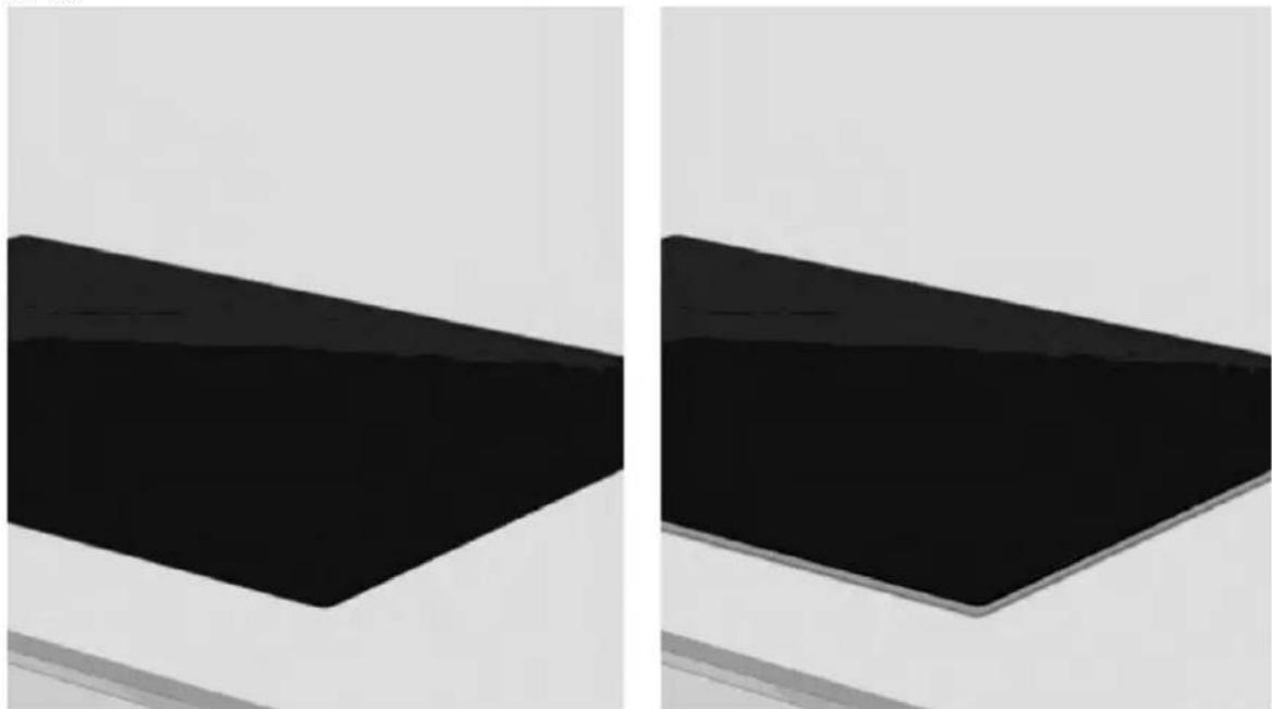
Place the hob centrally in the notch. Make sure the hob gasket rests on the worktop so that a seal is guaranteed.
a.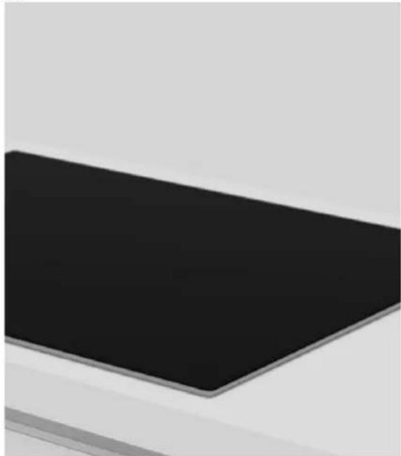
b.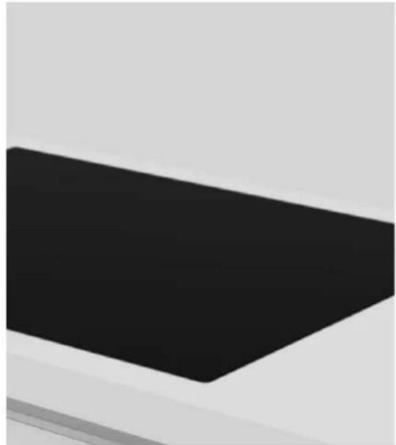
9
a. For standard installation: installation completed; b. For flush installation: follow the steps on the next pages;
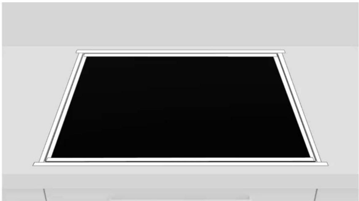
10
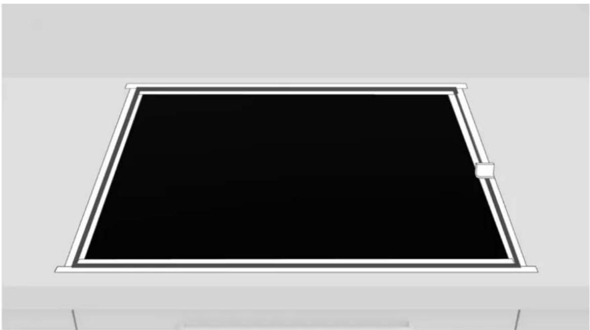
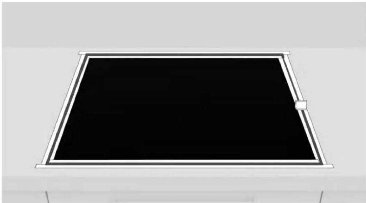
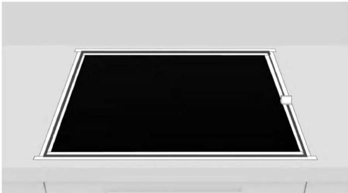
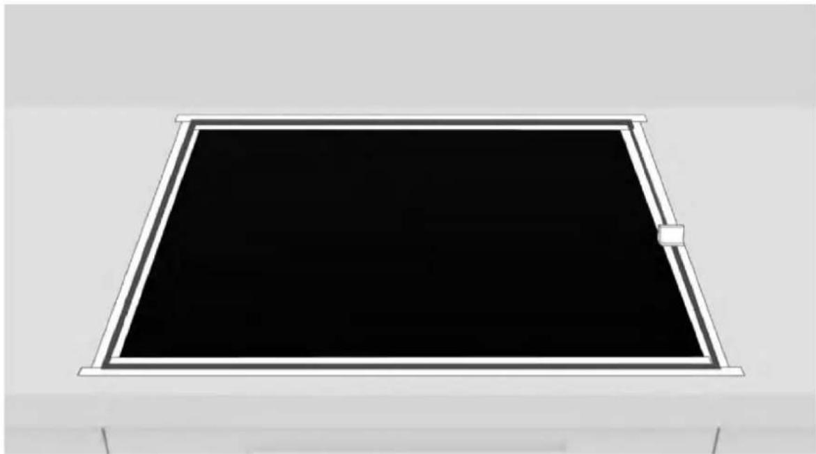
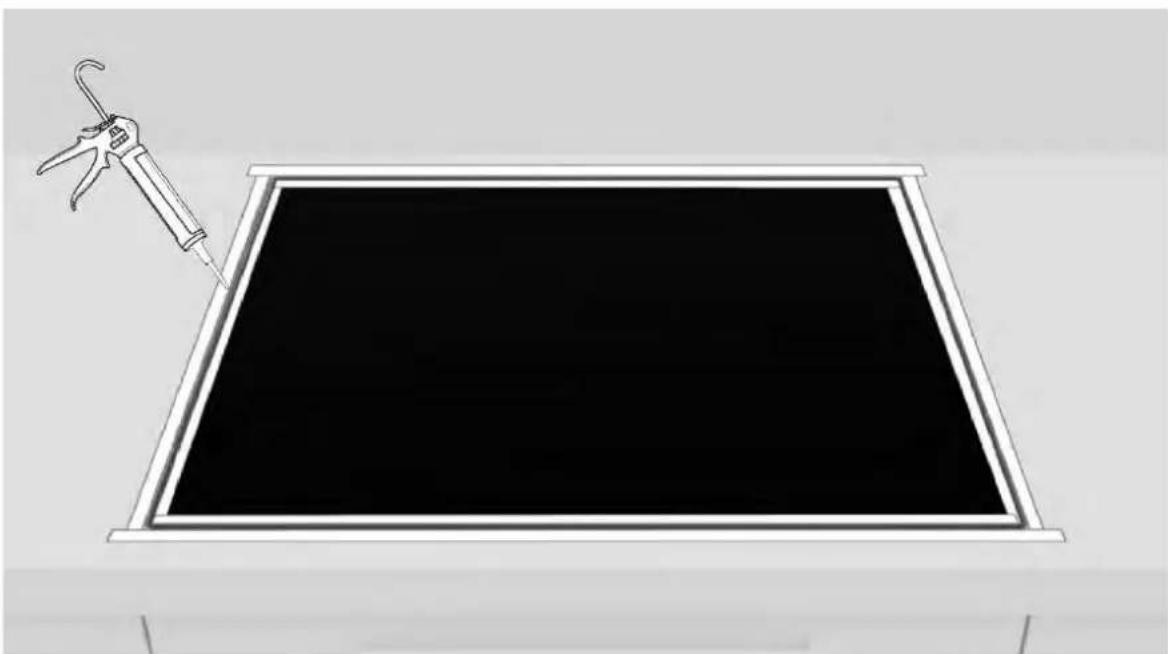
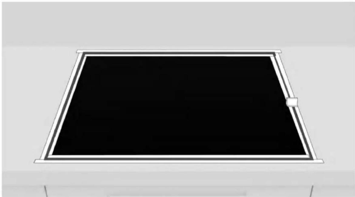
Apply tape to both the inside and outside of the edge;
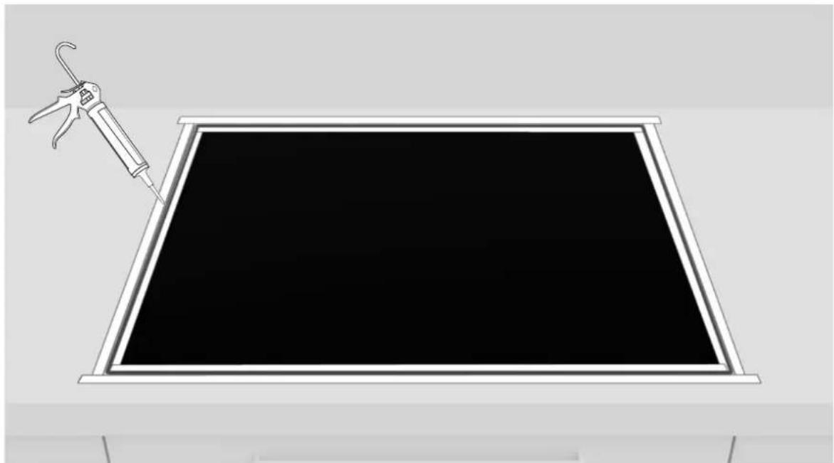
11
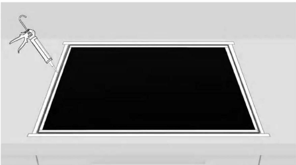
Apply the silicone.
9 Installation instructions
12
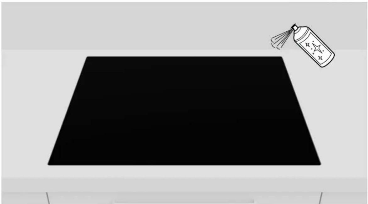
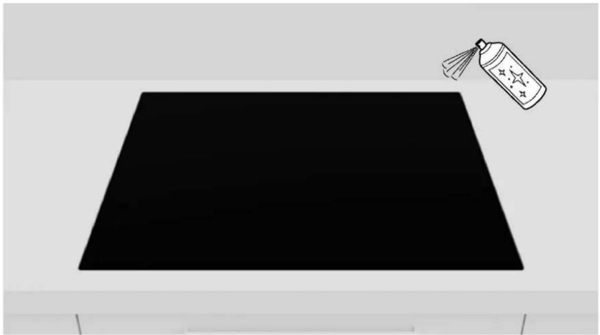
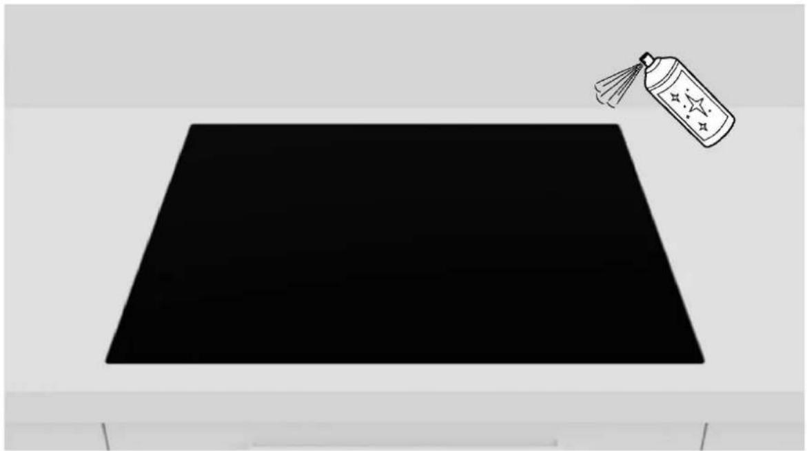
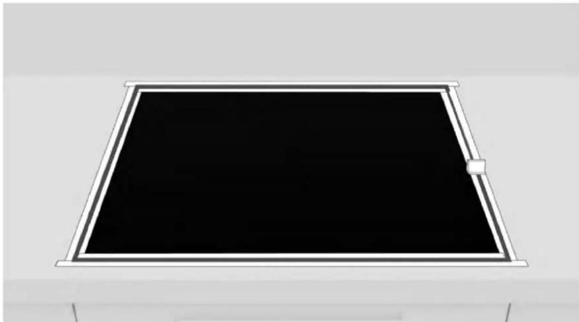
Remove excess silicone;
13
Remove the tape and clean the edges;
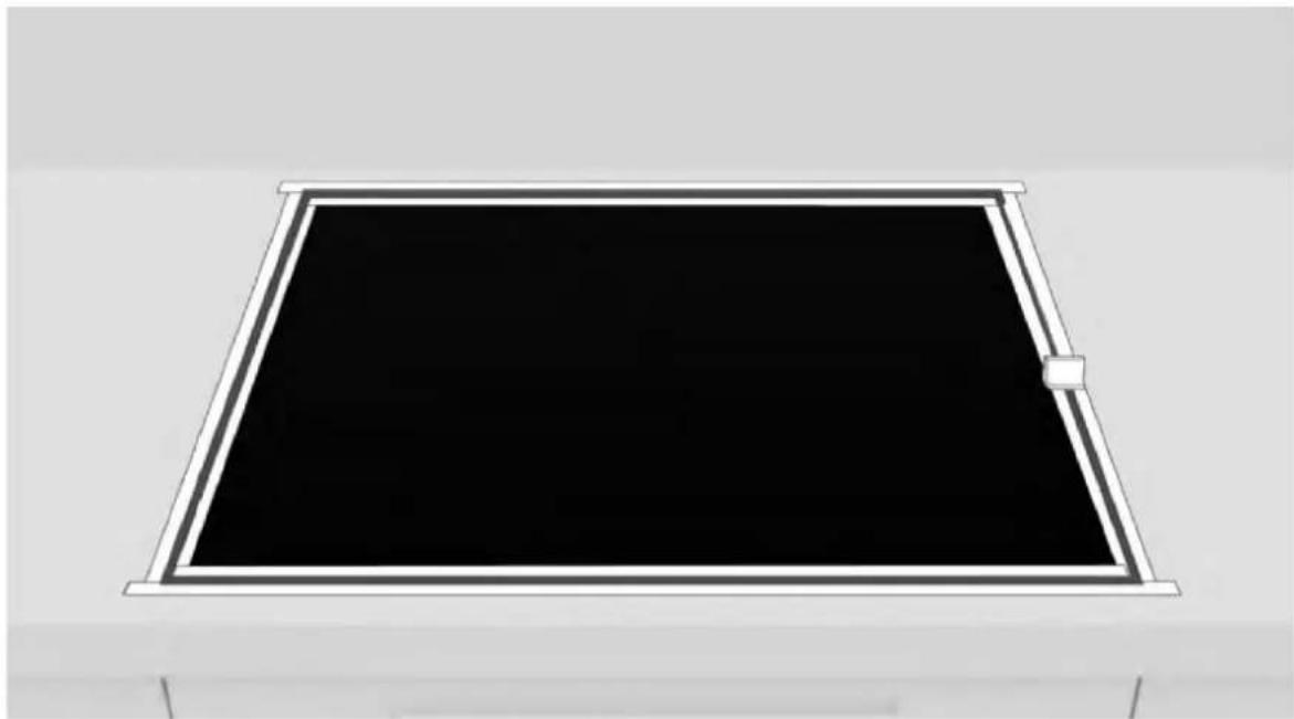
14
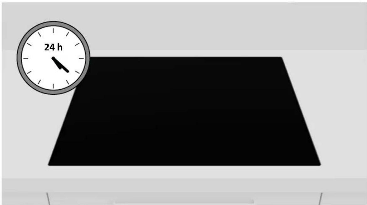
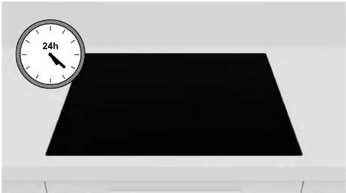
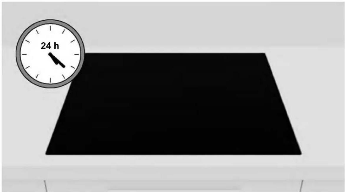
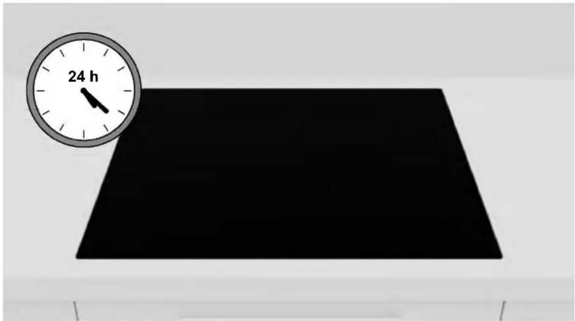
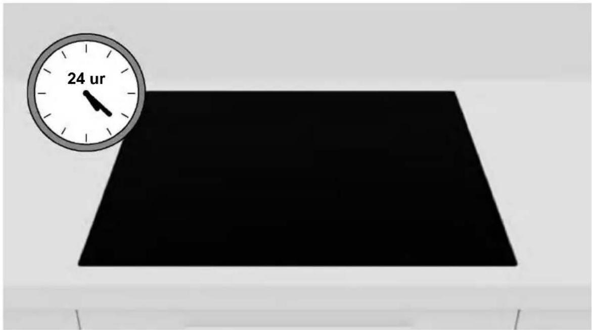
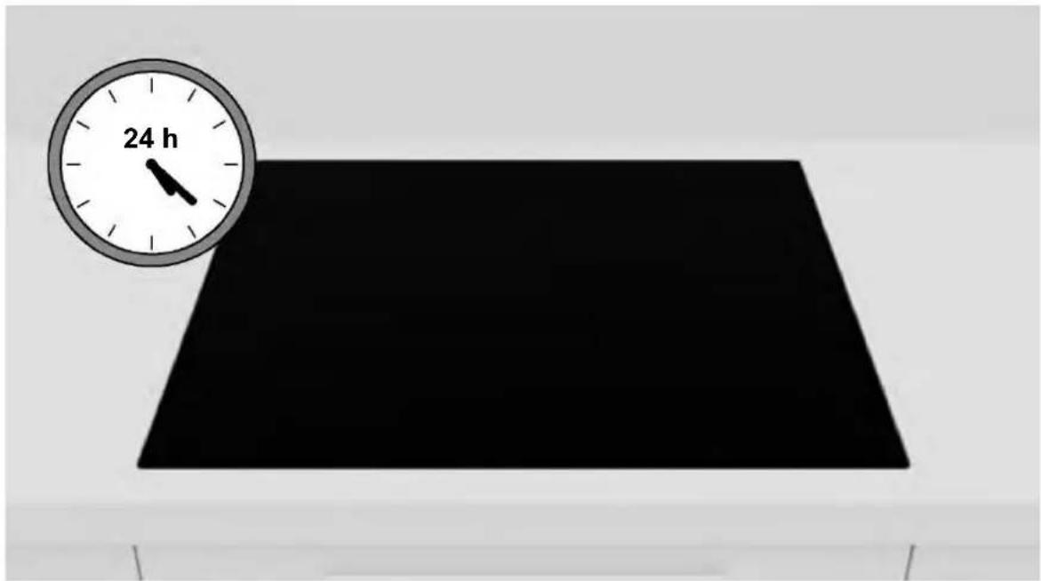
Wait 24 hours before starting up for the first time;
10 Delivery to the user
At the end of installation:
- Inform the user about essential functions;
- Inform the user about all aspects relevant to safe use and handling;
- Deliver accessories and instructions for use and assembly to the user to be kept with care.
After installation is complete, remove the protective film, tape, and all other packing materials.
⚠ WARNING: The product requires adequate ventilation for normal operation. Do not obstruct the ventilation openings for any reason.
NOTE: The actual appearance of the product depends on the model chosen.
11 First startup
When product is first used, the hob is set to maximum reachable power. Different power limits can be chosen according with home main supply system by using power management function.
How to set the power management
It is possible to set a maximum power absorption level for the Induction hob, choosing up to different power ranges. Induction hobs are able to limit themselves automatically in order to work at lower power level, to avoid the risk of overloading.
To enter Power Management Function:
- Turn on the hob, then press at the same time and Ⅱ,
- The timer indication will show "P8" which means power level 8. The default mode is on 7,4 kW.
To switch to another level
- Scroll left and right the slider to change the power management level;
- There are 8 power levels from "P1" to "PS". The timer indicator will show one of them:
| P1 P2 P3 | P4 P5 P6 P7 | P8 | |||||
| 2 kW 2,5 | kW 3 kW 3,5 | kW 4,5 kW 5,5 | kW 6,8 kW 7,4 kW | ||||
Disassembling the product
- Disconnect the product from the power supply;
- Lift the product slightly and pull it out completely;
- This product will not damage the cabinet, which can also be used with a new appliance.

WELCOME
9.2 Step-by-step installation
3
4
5
6
7
8
b.
9
10
11
12
13
WELCOME
Cooking plate
4 clips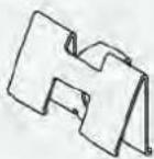
gasket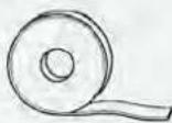
4 screws
5.1 Precautions
9.2 Step-by-step installation
3
4
5
6
7
8
9
a. For standard installation: installation complete.
10
Naneste silikon.
WELCOME
13
WELCOME
3
4
5
6
7
8
9
10
11
12
13
WELCOME
Countertop
clip x4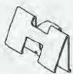
gasket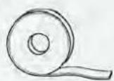
screws x4
5.1 Precautions
3
4
5
6
7
8
9
10
11
Apply the silicone.
12
13
TERE TULEMAST
Where to install the product
2
9.2 Step-by-step installation
3
4
5
6
7
8
9
10
11
Apply silicone.
9 Installation instructions
12
13
Product disassembly
WELCOME
standard installation
standard installation
standard installation
Standard installation
3
4
5
6
7
8
9
10
11
Apply the silicone.
12
13
WELCOME
Cooktop
bracket x4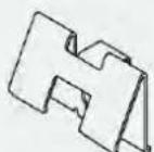
gasket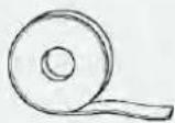
screws x4
4.2 Top mounting plate
Required tools
Cooktop
bracket x4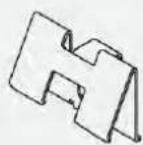
5.1 Safety precautions
• With regard to safety, this product complies with current regulations; - Maintain a side safety distance from furniture (D). Furniture side panels must be made of heat-resistant material; - The distance between the hob and furniture or built-in appliances must be such as to guarantee sufficient ventilation and adequate air exhaust; - The minimum distance between the hob recess and the kitchen back panel must be at least 35 mm; - The minimum distance between the hob and the hood depends on the hood model; - The distance between the hob and wall units must take into account the presence of bulky objects (pots, ladles, etc.) and their use; - In the area below the hob, a gap of at least 10 mm must be maintained between the hob itself and any other object, since the latter may be affected by the heat generated during use; • For product ventilation, follow the instructions in this manual; - If the product is installed above an oven, also refer to the oven installation instructions.
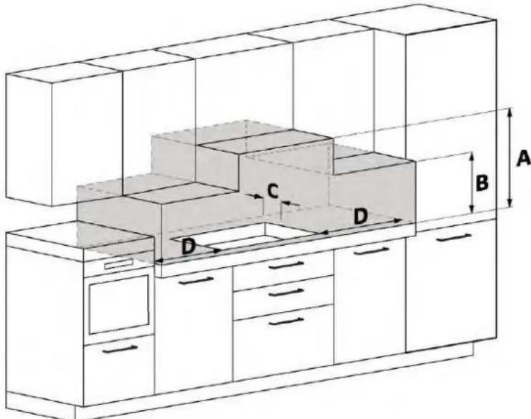
A We recommend a distance of at least 650 mm, but refer to the hood manual; B Consider the useful space for handling pots, ladles, and other objects; C Distance of 35 mm from the recessed opening to the back panel/riser; D 35 mm: L60 hob; 55 mm: L65 hob; 35 mm: L80 hob;
6.1 Width 60 – 65 – 80 on oven base
- Do not secure the hob with silicone or any other adhesive! This fixing would damage the product if it were disassembled (fig. 3).
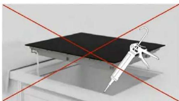
fig. 3
9.2 Step-by-step installation
3
Place the hob upside down on a cloth previously spread on the side of the packaging;
4
Apply the gasket around the perimeter;
5
Attach the clips to the short sides of the hob;
6
7
8
Place the cooktop in the center of the cutout. Make sure the cooktop gasket sits on the countertop so that the seal is guaranteed.
a. b.
9
10
11
Apply silicone.
9 Installation instructions
12
Remove excess silicone;
13
Remove the strap and clean the edges;
14
WELCOME
Hob
bracket x4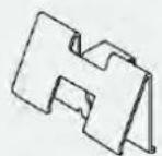
seal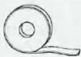
screw x4
Hob
bracket x4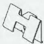
seal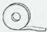
screw x4
5.1 Precautions
3
4
5
6
7
8
9
10
11
12
13
CONGRATULATIONS
Hob
mounting brackets x4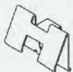
sealing tape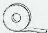
screws x4
9.2 Installation steps
3
4
5
6
7
8
9
10
11
Apply silicone.
12
13
STEP LADDER
Stove surface
screws x4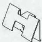
gasket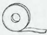
screws x4
Stove surface
screws x4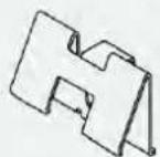
glue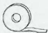
screws x4
3
4
5
6
7
8
9
10
11
Apply silicone.
12
Remove excess silicone;
13
Do not bend or damage the edges;
14
WELCOME
Cooktop
clamps x4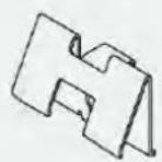
gasket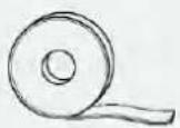
screws x4
Cooktop
clamps x4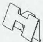
gasket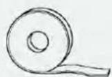
screws x4
3
4
5
6
7
8
9
10
11
12
13
WELCOME
Cooktop
latch x4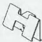
gasket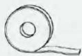
screws x4
3
4
5
6
7
8
9
10
11
Apply silicone.
12
Remove excess silicone;
13
WELCOME
Cooktop
clips x4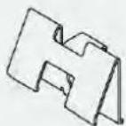
sealing gasket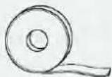
screws x4
4.2 Recessed flush with the worktop surface
silicone
cooktop
clips x4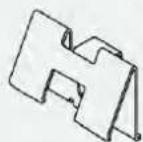
sealing gasket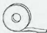
screws x4
5.1 Precautions
3
4
5
6
7
8
9
10
11
Apply the silicone.
12
13
Remove the adhesive tape and clean the edges;
14
BUN VENIT
Hob
clamp x4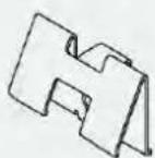
gasket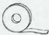
screws x4
silicone
Hob
clamp x4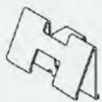
gasket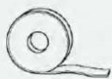
screws x4
9.2 Step-by-step installation
2
3
4
5
6
7
8
9
10
11
Apply the silicone.
12
13
WELCOME
Hob
clip x4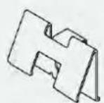
gasket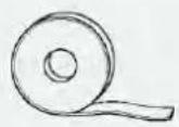
screws x4
4.2 Installation wire-top side
Required tools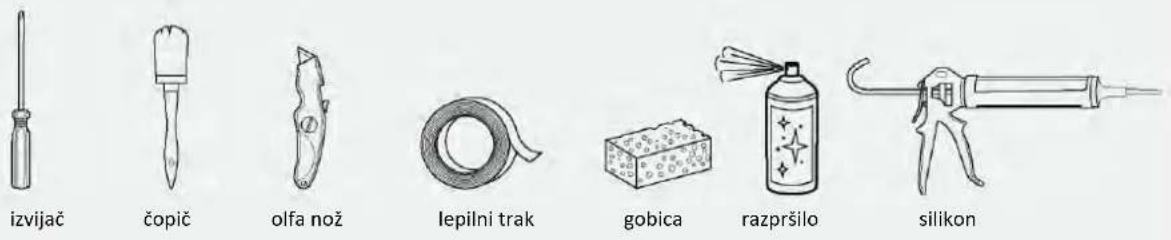
Hob
clip x4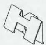
gasket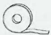
screws x4
5.1 Safety precautions
fig. 3
3
4
Apply the sealant around the perimeter;
5
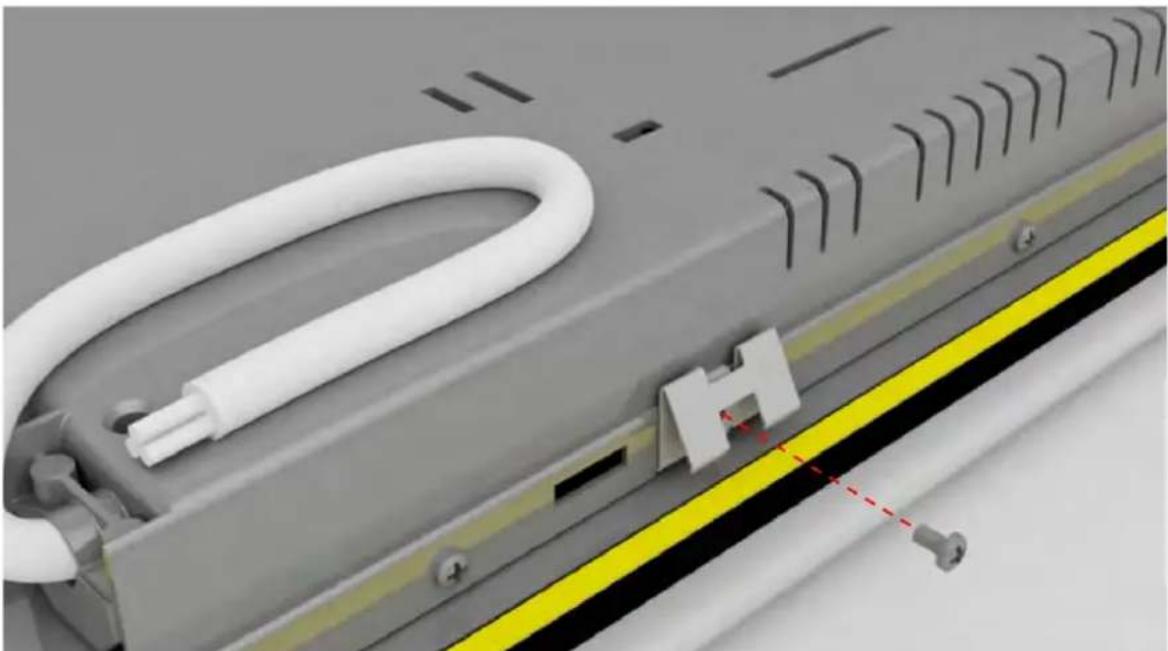
Attach the clips to the short sides of the hob;
6
7
8
9
10
Apply adhesive tape to the inner and outer sides of the edge;
11
Apply silicone.
12
13
Remove the adhesive tape and clean the edges;
14
WELCOME
This installation instruction is intended for kitchen manufacturers who will install these products. To ensure safety and achieve the best results, carefully read this instruction, including the safety instructions, and keep it for future use. Before proceeding with installation, pay attention to the serial number, as it may be needed in case of repairs. Check for any transport damage and consult a technician if in doubt before use. Always keep all packaging material at a safe distance from children.
i NOTE: The features, images contained in the instruction, and the product's additional equipment may vary depending on the purchased model.
index
Cooktop
clip x4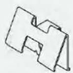
gasket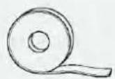
screws x4
Cooktop
clip x4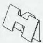
gasket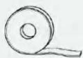
screws x4
A We recommend a distance of at least 650 mm, but refer to the hood's instruction;
B Consider the useful space for handling pots, pans, and other items;
C 35 mm from the recessed opening to the backrest/riser;
D 35 mm: plate L60;
55 mm: plate L65;
35 mm: plate L80;
6.1 Width 60 - 65 - 80 on the oven
- The supporting surface of the hob must be perfectly smooth so that it rests evenly and the applied seal can guarantee sufficient sealing (fig. 2).
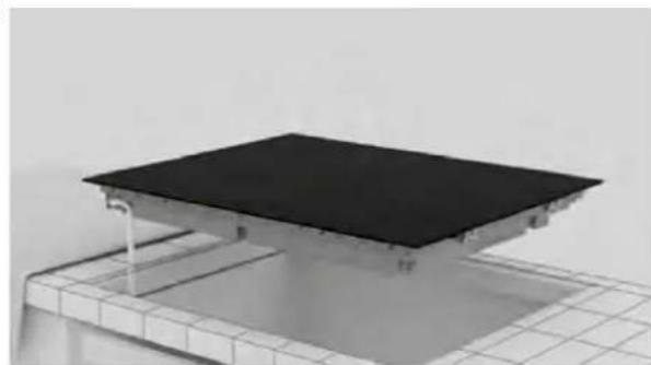
fig. 3
9.2 step-by-step installation
3
4
Apply the seal around the perimeter;
5
6
Clean the edge of the recessed space;

7
Connect the power cable in accordance with the connection diagram specified in the "Connection to the electrical network" section of the manual (no other object should be on the cooking plate during connection to the electrical network).
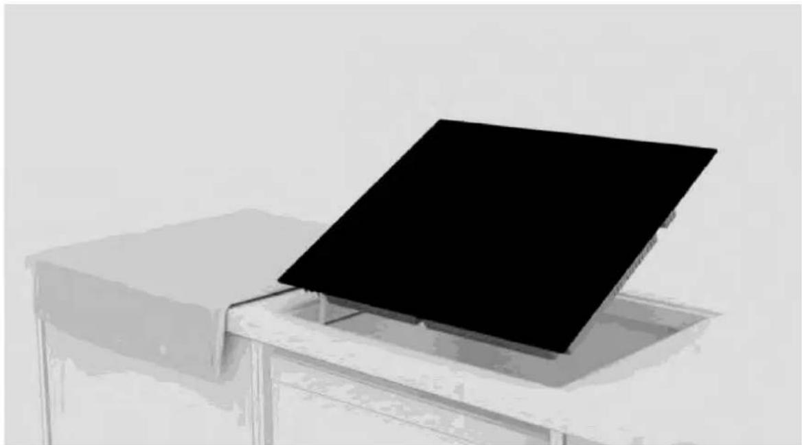
8
9
a. For standard installation: installation completed;
10
Apply adhesive tape both inside and outside the edge;
11
Apply silicone.
12
Remove excess silicone;

13
Remove the tape and clean the edges;
14
WELCOME
3
4
Apply sealant around the perimeter;
5
6
7
8
b.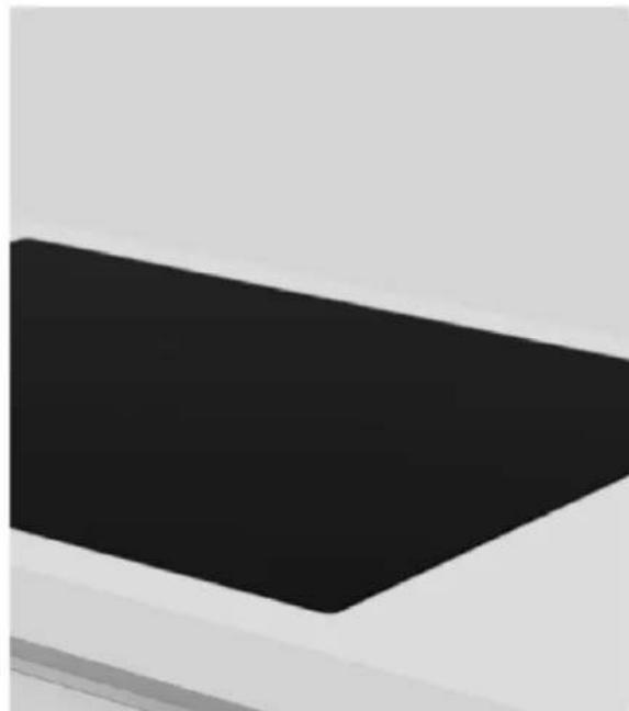
9
10
11
Apply silicone.
12
13
Haier
- WELCOME
- INDEX
- OBSERVE THESE DIRECTIONS BEFORE BEGINNING THE INSTALLATION OF THE PRODUCT
- WHERE TO INSTALL THE PRODUCT
- OTHER TIPS
- HOB DIMENSIONS
- WIDTH
- PRODUCT CODES
- INSTALLATION TOOLS
- STANDARD INSTALLATION
- FLUSH INSTALLATION
- PRECAUTIONS
- WIDTH 60 - 65 - 80 ON OVEN BASE
- WIDTH 60 - 65 - 80 ON BASE WITH DRAWERS
- WIDTH 60 - 65 - 80 ON BASE WITH SHELVES
- BUILT-IN DIMENSIONS
- HOB WIDTH
- SAFETY WARNINGS
- TO CARRY OUT THE ELECTRICAL CONNECTION OF THE DEVICE SAFELY, OBSERVE THE FOLLOWING WARNINGS
- INSTRUCTIONS
- POWER ABSORBED
- DIFFERENTIAL CIRCUIT BREAKER (LIFE-SAVING)
- SEPARATION DEVICES
- ELECTRICAL POWER CABLE
- REPLACING THE POWER CORD
- OTHER ADVICE
- CONNECTION DIAGRAM
- CONNECTING THE APPLIANCE
- IMPORTANT WARNINGS
- STEP-BY-STEP INSTALLATION
- INSTRUCTIONS FOR INSTALLATION
- INSTALLATION INSTRUCTIONS
- DELIVERY TO THE USER
- FIRST STARTUP
- HOW TO SET THE POWER MANAGEMENT
- TO ENTER POWER MANAGEMENT FUNCTION
- TO SWITCH TO ANOTHER LEVEL
- DISASSEMBLING THE PRODUCT
- TERE TULEMAST
- PRODUCT DISASSEMBLY
- TOP MOUNTING PLATE
- SAFETY PRECAUTIONS
- WIDTH 60 – 65 – 80 ON OVEN BASE
- CONGRATULATIONS
- INSTALLATION STEPS
- STEP LADDER
- RECESSED FLUSH WITH THE WORKTOP SURFACE
- BUN VENIT
- INSTALLATION WIRE-TOP SIDE
- WIDTH 60 - 65 - 80 ON THE OVEN
- HAIER
Brand : HAIER
Model : HAIF64IRB1S
Category : Cooker