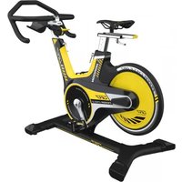
GR7 - Indoor bike trainer Horizon - Free user manual and instructions
Find the device manual for free GR7 Horizon in PDF.


User questions about GR7 Horizon
0 question about this device. Answer the ones you know or ask your own.
Ask a new question about this device
Download the instructions for your Indoor bike trainer in PDF format for free! Find your manual GR7 - Horizon and take your electronic device back in hand. On this page are published all the documents necessary for the use of your device. GR7 by Horizon.
USER MANUAL GR7 Horizon
natural_image
Silhouette of a person riding a stationary bike (no text or symbols)GR7 GR7s

OWNER'S MANUAL
BEDIENUNGSANLEITUNG
GEBRUIKERSHANDLEIDING
MANUEL D'UTILISATION
3 ENGLISH
35 DEUTSCH
67 NEDERLANDS
99 FRANÇAIS
H215GR7-DR76CNrl_0_Ained 23562718 11:30 AM
IMPORTANT SAFETY INSTRUCTIONS SAVE THESE INSTRUCTIONS
READ ALL INSTRUCTIONS BEFORE USING THIS EXERCISE EQUIPMENT.
- Keep children off your Bike at all times.
- When the Bike is in use, young children and pets should be kept at least 10 feet away.
- Use this Bike only for its intended use as described in the manual.
- Keep your hands away from all moving parts. Never turn the pedal crank arms by hand.
- Do not remove your feet from the pedals while they are in motion.
- After exercising, push down on the tension knob or turn the tension knob in a clockwise direction to slow the flywheel down and decrease the potential for injury.
- Do not dismount the Bike until both the pedals and flywheel have come to a complete stop.
- Do not attempt to use this Bike at high speeds or in standing positions until you have practiced and are comfortable at lower speeds.
- Rotate the tension knob clock wise to add resistance to the flywheel prior to standing on the pedals.
- Never drop or insert any object into any opening on this Bike.
• Do not use without proper footwear. - Rotate the tension knob clock wise to lock the flywheel when not in use.
To assure that the safety level of this Bike is maintained, examine components for wear and tear on a regular basis.
Components that are worn excessively or inoperable should be replaced immediately or the Bike should be put out of use until it is repaired.
CAUTION!
If you experience chest pains, nausea.
dizziness or shortness of breath.
stop exercising immediately and consult your physician before continuing.
This application is only for indoor use at home, not recommend to use in commercial environment
H215_GR7-2RnCNW1_0_Ained 4560218 1130 AM
HOW TO MOVE THE INDOOR CYCLE
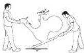
Due to the weight of the Indoor Cycle, it is recommended that two persons move it. While one person lifts the back of the indoor cycle, the second person firmly holds the handlebar and tips the indoor cycle forward until it rolls on the wheels. Carefully move the Indoor Cycle to the desired location and then lower it.
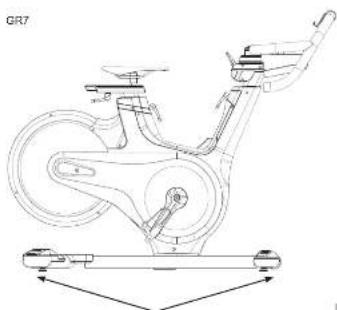
If the Indoor Cycle rocks on the floor after being set down, turn the leveling feet underneath the front or rear stabilizer until the rocking motion is eliminated.
Firmly grasp the handlebars, carefully tip toward you, and roll on the transport wheels.
LOCATION OF THE
INDOOR CYCLE
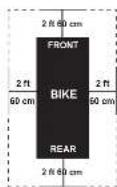
Place the Indoor Cycle on a level surface. There should be 2 feet (60 cm) of each side surround the Indoor Cycle. Do not place the cycle in any area that will block any vent or air openings. The Indoor Cycle should not be located in a garage, covered patio, near water or outdoors.
WARNING
To reduce the risk of injury, use extreme caution while moving the indoor cycle. Do not attempt to move it over uneven surfaces and make sure there's a safety space of 20 inch (minimum) to the nearest equipment is recommended.

natural_image
Technical line drawing of a stationary bike with labeled components and motion arrows (no text or symbols)Leveling Feet

HOW TO ADJUST THE INDOOR CYCLE
The Indoor Cycle can be adjusted for maximum comfort and exercise effectiveness. The instructions below describe one approach to adjusting the Indoor Cycle to ensure optimal user comfort and ideal body positioning: you may choose to adjust the Indoor Cycle differently.
natural_image
Technical line drawing of a stationary bike with suspension components and wheel (no text or labels)SADDLE ADJUSTMENT
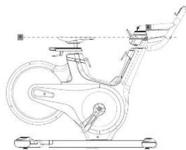
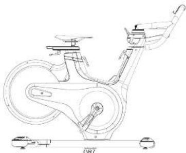
Proper saddle height helps ensure maximum exercise efficiency and comfort, while reducing the risk of injury. Adjust the saddle height to make sure it's in proper position, one that keeps a slightly bend in your knee while your legs are in the extended position.
HANDLEBAR ADJUSTMENT
Proper position for the handlebar is based primarily on comfort. Typically, the handlebar should be positioned slightly higher than the saddle for beginning cyclists. Advanced cyclists could try different heights to get the arrangement most suitable for you.
6
H215_GR7-2RnCNW1_0_Ained 8-762218 11:30 AM
natural_image
Technical line drawing of a stationary bike with labeled components (no text or symbols beyond 'GR7' label)TO ADJUST THE SADDLE HEIGHT:
Rotate the adjustment lever counterclockwise and adjust the saddle to a comfortable pedaling position. Rotate the lever clockwise to lock saddle position.
TO ADJUST THE SADDLE HORIZONTAL POSITION:
Rotate the adjustment lever counterclockwise to slide the saddle forward or backward as desired. Rotate the lever clockwise to lock saddle position. Test the saddle slide for proper operation.

7

text_image
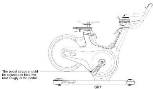
The pedal straps should be adjusted to hold the foot snugly in the pedal. GR7TO ADJUST THE HANDLEBAR HEIGHT:
Rotate the adjustment lever counterclockwise to adjust the handlebar height. Raise or lower the handlebar to the desired height. Rotate the lever clockwise to lock handlebar position.
TO ADJUST THE PEDAL STRAPS:
Place each foot ankle on the pedal and in the toe clip that the foot ankle is centered over the pedal spindle (center of the pedal). Rotate one foot to arms reach and pull up on the toe clip strap. Repeat for the other foot. Keep your knees over your feet as you pedal. To remove your foot from the toe clip, loosen the strap and pull out.
8
H215_GR7-2RnCNW1_0_Ained 8-962218 11:30 AM
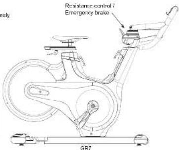
The preferred level of difficulty in pedaling (resistance) can be regulated in fine increments by use of the resistance control lever. To increase the resistance, push down the resistance control lever. To decrease the resistance, pull up the lever.
IMPORTANT:
• To stop the flywheel while pedaling, push down to extremely on the resistance control lever.
- The flywheel should quickly come to a complete stop.
- Make sure your shoes are loaded into the tire.
- Apply full resistance load when the bike is not in use to prevent injuries due to moving drive gear components.

WARNING
The Indoor Cycle does not have a free moving flywheel; the pedals will continue to move together with the flywheel until the flywheel stops. Reducing speed in a controlled manner is required. To stop the flywheel immediately, push down to extremely on the resistance control lever. Always pedal is a controlled manner and adjust your desirable distance according to your own abilities. Push down extremely the resistance control lever down = emergency stop.
text_image
Resistance control / Emergency brake GR7

WARNING
The Indoor Cycle uses a fixed flywheel that builds momentum and will keep the pedals turning even after the user stops pedaling or if the user's foot slip off. DO NOT ATTEMPT TO REMOVE YOUR FEET FROM THE PEDALS OR DISMOUNT THE MACHINE UNTIL BOTH THE PEDALS AND THE FLYWHEEL HAVE COMPLETELY STOPPED. Failure to follow these instructions may lead to loss of control and the potential for serious injury.
9
ASSEMBLY

WARNING
There are several areas during the assembly process that special attention must be paid. It is very important to follow the assembly instructions correctly and to make sure all parts are firmly tightened. If the assembly instructions are not followed correctly, the indoor cycle could have parts that are not tightened and will seem loose and may cause irritating noises. To prevent damage to the indoor cycle, the assembly instructions must be reviewed and corrective actions should be taken.
Before proceeding, find your indoor cycle's serial number located on the front base frame of the cycle and enter it in the space provided below
ENTER YOUR SERIAL NUMBER IN THE BOX BELOW:
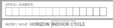
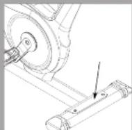
- Refer to the SERIAL NUMBER and MODEL NAME when calling for service. - Be sure to enter both the SERIAL NUMBER and MODEL NAME on your warranty card.
H2*8_GR7-0FwOW r1_0_Ained 10-11 B2715 11:30 AM


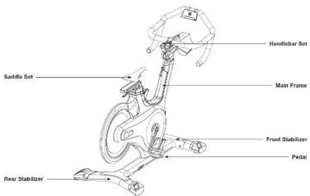
MODEL INFORMATION
text_image
Saddle Set Handlebar Set Main Frame Front Stabilizer Pedal Rear StabilizerH215_GR7-2RmCN/1_0_Ained 12-13 82n15 11:35 AM
MAIN PARTS INCLUDED:
□ Main Frame
□ Front & rear stabilizer
□ Handlebar Set
Saddle Set
□ Pedals
PRE ASSEMBLY
UNPACKING
Due to the weight of the indoor cycle, it is recommended that two persons perform the assembly. Set the indoor cycle in a cleared area and remove all packing materials: do not dispose of the packing materials until assembly is completed.
NOTE: During each assembly step, ensure that ALL nuts and bolts are in place and partially threaded in before completely tightening any ONE bolt.
NOTE: A light application of grease may aid in the installation of hardware. Any grease, such as lithium bike grease is recommended.

NEED HELP?
If you have questions or if there are any missing parts, contact your local dealer. Contact information may be located on the back panel of this manual or on warranty card.


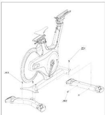
ASSEMBLY STEP 1

text_image
Technical diagram of a stationary exercise bike with labeled components and assembly partsA Attach FRONT STABILIZER to the MAIN FRAME using BOLTS (2 x Z01 and 2 x Z02) and fasten by ALLEN WRENCH.
B Attach REAR STABILIZER to the MAIN FRAME using BOLTS (3 x Z01) and fasten by ALLEN WRENCH.

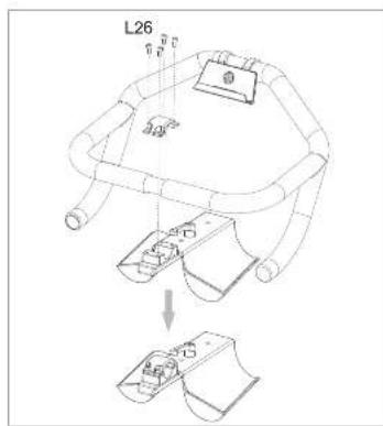
ASSEMBLY STEP 2-1 (for GR7)
text_image
L26A. Release the 4 x BOLTS (L26) from the BOTTLE HOLDER.
B Attach HANDLEBAR to the BOTTLE HOLDER using FASTEN PLATE (G03) and 4 x BOLTS (L26) then fasten by ALLEN WRENCH.


H215_GR7-2RmOW/1_0_Ained 14-15 82p16 11:35 AM
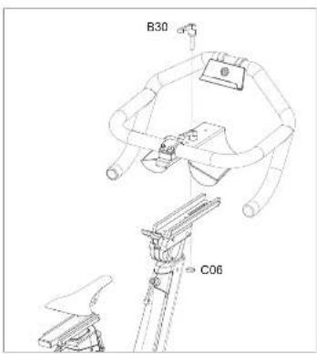
ASSEMBLY STEP 2-2 (for GR7)
text_image
B30 C06A Release KNOB (B30) and FIXING BASE (C06).
B Attach HANDLEBAR to the CONSOLE MAST using KNOB (B30) and FIXING BASE (C06).

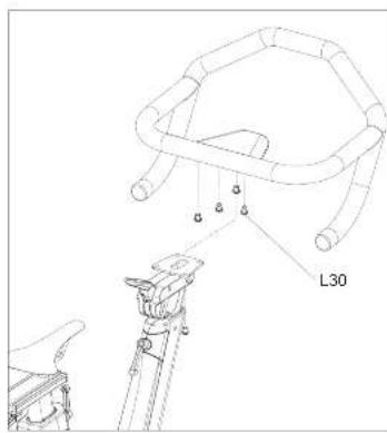
ASSEMBLY STEP 2 (for GR7s)
text_image
L30A. Release 4 x BOLTS (L30) from the bottom of HANDLEBAR.
B Attach HANDLEBAR to the CONSOLE MAST using 4 x BOLTS (L30) and fasten by ALLEN WRENCH


H215_GR7-2RmCN/T_0_Ained 18-17 82/15 11:35 AM
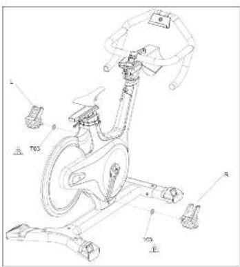
ASSEMBLY STEP 3 (GR7)
text_image
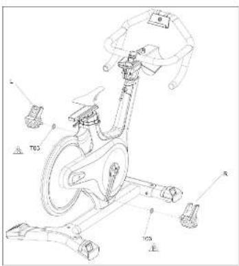
Technical diagram of a stationary exercise bike with labeled components and measurement annotationsA Release PEDAL (R) onto the CRANK in the right hand side, between CRANK and PEDAL (R), A WASHER (T03) is necessary. Then lighten the PEDAL (R) by WRENCH.
B Repeat the assembly process on the left hand side.

TO3
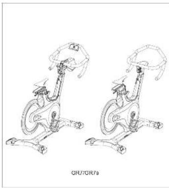
ASSEMBLY STEP 4
natural_image
Line drawing of two exercise bikes in a seated posture, no text or symbols presentASSEMBLY COMPLETE!
GR7
Dimension: 134 x 56.2 x 105.8 cm / 53" x 22" x 42"
Product Weight: 51 kg / 112 lbs.
Max. User Weight: 136 kg / 300 lbs.
GR78
Dimension: 130.5 x 56.2 x 105.8 cm / 51" x 22" x 38"
Product Weight: 49 kg / 108 lbs.
Max. User Weight: 136 kg / 300 lbs.


H215_GR7-GRwOW/n_0_Ajnd 16-19 82n15 11:35 AM
TROUBLESHOOTING & MAINTENANCE
H215_GR/GR/SW n1_0_Ained 20-21 B2713 11:30 AM

COMMON PRODUCT QUESTIONS
ARE THE SOUNDS MY Indoor Cycle MAKES NORMAL?
Our Indoor Cycles are some of the quietest available because they use belt drives and cantilever brake resistance. We use the highest grade bearings and chains/belts to minimize noise. However, because the resistance system itself is so quiet, you will occasionally hear other slight mechanical noises. Unlike older, louder technologies, there are no tans, friction belts, or stemator noises to mask these sounds on our Indoor Cycles. These mechanical noises, which may or may not be intermittent, are normal to be used in the absence of mechanical noise. The most important features of all bearings, chains/belts and other rotating parts will generate some noise which will transfer through the casing and frame. It is also normal for these sounds to change slightly during a workout and over time because of thermal expansion of the parts.
WHY IS THE Indoor Cycle I HAD DELIVERED LOUDER THAN THE ONE AT THE STORE?
All fitness products seem quieter in a large store showroom because there is generally more background noise than in your home. Also, there will be less reverberation on a carpeted concrete floor than on a wood overlay floor. Sometimes a heavy rubber mat will help reduce reverberation through the floor. If a fitness product is placed close to a wall, there will be more reflected noise.
HOW LONG WILL THE BELT LAST?
The computer modeling we have done indicated virtually thousands of maintenance free hours. You should not have to replace the belt as long as you have the Indoor Cycle.
CAN I MOVE THE Indoor Cycle EASILY ONCE IT IS ASSEMBLED?
Your Indoor Cycle has a pair of transport wheels built into the front stabilizer tube. Please follow the moving the Indoor Cycle section to transport your Indoor Cycle. It is important that you place your Indoor Cycle in a comfortable and inviting room. Your Indoor Cycle is designed to use minimal floor space. Many people will place their Indoor Cycles facing the TV or a picture window. If at all possible, avoid putting your Indoor Cycle in an unfinished basement. To make exercise a desirable daily activity for you, the Indoor Cycle should be in a comfortable setting.
ENGLISH
H215_GR/CRsCNr1_0_Ained 22-29-827*3 11:35 AW
TROUBLES HOOTING
PROBLEM: The Indoor Cycle makes a squeaking or chirping noise.
SOLUTION: Verify the following.
• The Indoor Cycle is on a level surface.
- Loosen all bolts attached during the assembly process, grease the threads, and tighten again.
If this does not remedy the problem, you may CONTACT CUSTOMER TECH SUPPORT AT THE NUMBER ON THE INFORMATION CARD.
The following information may be asked of you when you call. Please have these items readily available:
- Model Name
• Proof of Purchase (receipt or credit card statement)
You may find more troubleshooting suggestions on the customer support section of our website. Contact customer support using the contact information on the INFORMATION CARD.
In order for Customer Tech Support to service your Indoor Cycle they may need to ask detailed questions about the symptoms that are occurring. Some troubleshooting questions that may be asked are:
• How long has this problem been occurring?
- Does this problem occur with every use? With every user?
- If you are hearing a noise, does it come from the front or the back? What kind of noise is it (thumping, grinding.
squeaking, chirping etc.)?
- Has the machine been lubricated and maintained per the maintenance schedule?
Answering these and other questions will give the technicians the ability to send proper replacement parts and the service necessary to get you and your Indoor Cycle running again!

ENGLISH
2322

MAINTENANCE
The safety level given by the design of the Indoor Cycle can only be maintained when the equipment is regularly examined for damage and wear. Inoperable components should be replaced or the equipment should be put out of use until it is repaired.
DAILY
- Wipe down the Indoor Cycle after each use to remove sweat and moisture. Use soap and water, or a diluted non-abrasive dementic plume solution. Prices in summer decreased significantly and then day off.
- Before each session, inspect for loose components such as pedals or cranks prior to commencing the next use. Tighten up any loose parts.
WEEKLY
- Check for proper flywheel alignment. Torque flywheel nuts as necessary.
- Remove chain guard and check for loose chain. Adjust and lubricate the chain as necessary.
- Check to make sure the crank arms are tight to the bottom bracket.
- Inspect all parts, nuts, bolts, or screws for adjustments, replacements or maintenance.
MONTHLY
- Inspect the frame and main assembly components for rust or corrosion. Till the cycle or place in an upside down position to locate areas where rust and corrosion may develop. Use a small, wire brush to remove rust build-up in small crevasses, such as leveling feet, quick release levers and other bolt assemblies.
- Inspect all wear items for adjustments or possible part replacement. Give particular attention to the following:
A) Inspect brake pad for wear. Excessive wear or dryness indicates replacement is required.
B) Inspect seal pad for wear. Rips, tears or excessive movement indicates replacement is required.
C) Inspect pedals for play. Excessive movement of pedals indicates replacement is required.
- Inspect the chain for tensioning by rotating the crank to drive the flywheel forward. Do this motion in 1/4 turns to assess if there is free play between the crank and the flywheel.
- Dryness or prolonged use may cause the height and reach adjustments for the seat and handlebar to become tight. If this is the case, the sliding assembly should be removed from the frame and have a smear of light duty grease applied along the sliding surface before assembly. Similarly, apply some light grease to the clamping assembly to ensure it does not seize up. Clean off excessive grease before reassembly.
- Please lubricate the seal post, brake pad and handlebar adjustment regularly with lubricant in your parts package.
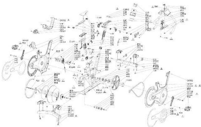
GR7 EXPLODED VIEW
text_image
Technical schematic diagram of a mechanical assembly with labeled components and assembly details
ENGLISH
2524
H215GR/CR/SOM1_0_Ained 24-25 B2718 1130 AW
GR7 PARTS LIST

| NO. | DESCRIPTION: CTY | |
| A61 | FRAME SET 1 | |
| B17 | FASTEN PLATE/FRAME LEFT 1 | |
| B08 | FAF SPRING TOSION 2 | |
| B07 | SCREW 2 | |
| B18 | PRESSING BLOCK/FRAMERIGHT 1 | |
| B10 | KVOB 2 | |
| B14 | FIXING PLATE | 1 |
| B29 | CAPITRAWL/KINT | 1 |
| B29 | CAPITRAWL/BACK | 1 |
| B42 | SCREW 4 | |
| B39 | SPRING | 2 |
| B40 | SCREW 2 | |
| B60 | SCREW 2 | |
| B51 | NUT | 2 |
| F23 | TE STRAY ADHESIVE | 2 |
| F24 | SCREW 2 | |
| F25 | MOVABLE BUSHING | 0 |
| A61 | CONSOLE WAST SET | 1 |
| C06 | FIXING BASE/KVOR | 1 |
| C90 | FIXING BLOCK | 1 |
| NO. | DESCRIPTION QTY | |
| A02 | HAND FEAR | 1 |
| L05 | LOCATION HOOL | 1 |
| L20 | OVER | 1 |
| L21 | CYLER | 1 |
| S01 | STEEL ROPE | 1 |
| L15 | SWIVEL AXLE | 1 |
| L24 | SCREW | 2 |
| L25 | SCXLW | 7 |
| L29 | SCREW | 4 |
| L28 | SCXLW | 2 |
| L29 | SCREW | 2 |
| B26 | MP3 SUPPORT RACK | 1 |
| C03 | FASTEN PI ATF | 1 |
| C11 | CAP | 1 |
| B27 | KITTLE RACK | 1 |
| L05 | SPRING | 1 |
| L18 | SPRING PIN 1 | |
| L17 | STEEL BALL | 1 |
| B30 | KNOE 1 | |
| B111 | DAM PAD | 1 |
| NO. | DESCRIPTION: QTY | |
| R32 | FOAM PAD | 1 |
| C16 | FIX BUCKLE SET | 1 |
| L34 | HAND LUXER | 1 |
| L27 | SCREW | 2 |
| D41 | WAS-ER | 2 |
| C16 | SCREW | 1 |
| R43 | FOAM PAD | 1 |
| A11 | STABLUXER SELT | 1 |
| JX5 | SCREW | 2 |
| A12 | STABLUXER SELT | 1 |
| K30 | FOOT PAD | 4 |
| K13 | TRANSPORT WHEELS | 2 |
| F08 | CAP RIGHT-FRONT | 1 |
| F07 | CAP LEFT-FRONT | 1 |
| F09 | CAP LEFT REAR | 1 |
| F09 | CAP RIGHT REAR | 1 |
| FM | SCREW | 8 |
| A27 | SEAT SLEEVE SET | 1 |
| A22 | SEAT PAD ADJUSTABLE SET | 1 |
| D05 | GUIDE BLOCK | 1 |
| NO. | DESCRIPTION GTY | |
| R19 | S FAT PAD | 1 |
| D08 | CAP DOWN | 1 |
| C14 | RUG PLATE | 1 |
| U33 | KNOU 1 | |
| C07 | CAP UP | 2 |
| R18 | SHIM | 1 |
| R63 | DISK | 1 |
| T19 | MAGNET | 1 |
| T09 | JELL POLY-V | 1 |
| T04 | PLDAL SLTL-M | 1 |
| T10 | BEARING | 1 |
| T11 | BEARING | 1 |
| T12 | SWAP RING | 1 |
| T01 | GRANKL | 1 |
| T02 | GRANK-R | 1 |
| R13 | FIX PLATE | 2 |
| R64 | DISK | 1 |
| R05 | FIXING DISK | 1 |
| R06 | MAIN AM.F | 1 |
| R28 | BLARING | 2 |

ENGLISH
2726
H215GR7CR7CNr10Alncel 28-27
62/18 1:30 AM
GR7 PARTS LIST

ENGLISH
| NO. | DESCRIPTION: CTY | |
| D21 | WASHR 1 | |
| D22 | RUT 4 | |
| D23 | SCREW 1 | |
| R14 | WASHER 2 | |
| R07 | XLE 1 | |
| R08 | DLER 1 | |
| D24 | FACING 1 | |
| H26 | SCREW 1 | |
| R193 | NAP RING-C-SHAPED 1 | |
| R194 | NAP RING-C-SI-APLD 1 | |
| T05 | SCREW SET | 2 |
| T05 | WASHER 4 | |
| AR2 | SFDAL MAIN AX F | 1 |
| T13 | SCREW 2 | |
| R09 | PLASTIC RACK | 1 |
| R12 | XING PLATE | 1 |
| R27 | POWERFUL MAGNET | 2 |
| B66 | PLASTIC LINER | 2 |
| D45 | SCREW 1 | |
| H47 | RUT | 2 |
| NO. | DESCRIPTION QTY | |
| H07 | STRING | 1 |
| R37 | BATTERY | 1 |
| R36 | C8 | 1 |
| K09 | SPEED SENSOR WIRE | 1 |
| R41 | BATTERY BASE | 1 |
| R40 | MODULE YR VARIABLE RESISTANCE GROUP | 1 |
| R34 | FIXING BASE | 1 |
| R43 | APL FLOWER TWO-SOLD | 1 |
| R51 | CREW | 6 |
| K03 | CARRY 4 | |
| K32 | CREW 3 | |
| C83 | POSITION AXLE | 1 |
| R35 | COSPR 1 | |
| C85 | POSITION AXLL | 1 |
| C01 | SIDE COVER LEFT | 1 |
| C02 | SIDE COVER RIGHT | 1 |
| C03 | COVER FRONT | 1 |
| C04 | COVER_BACK | 1 |
| C05 | COVER_UP | 1 |
| C07 | XING PILAR | 4 |
| NO. | DESCRIPTION QTY | |
| Q08 | SCREW | 8 |
| Q09 | SCREW | 2 |
| Q08 | SCREW | 2 |
| Q11 | SCREW | 4 |
| Q13 | SCREW | 2 |
| V01 | DECAL-SIDE COVER LEFT-UP | 1 |
| V02 | DECAL-SIDE COVER LEFT-DOWN | 2 |
| V03 | DECAL-SIDE COVER LEFT-RCAR | 1 |
| V04 | DECAL-SIDE COVER RIGHT-UP | 1 |
| V06 | DECAL-SIDE COVER RIGHT-RCAR | 1 |
| V07 | DECAL HANDLE CAP-UP | 1 |
| V08 | WARNING LABEL-UP | 1 |
| V15 | FINT ARBI | 1 |
| V20 | DECAL-SIDE COVER MIDOLE | 4 |
| Z01 | SCREW | 5 |
| Z03 | WRENCH | 1 |
| Z02 | SCREW | 2 |
| Z04 | WRENCH 1 | |
| T03 | SHIM | 2 |
H215GR/CR/SOMR_C_Ained 28-29

ENGLISH
2926
62/18 1:30 AM

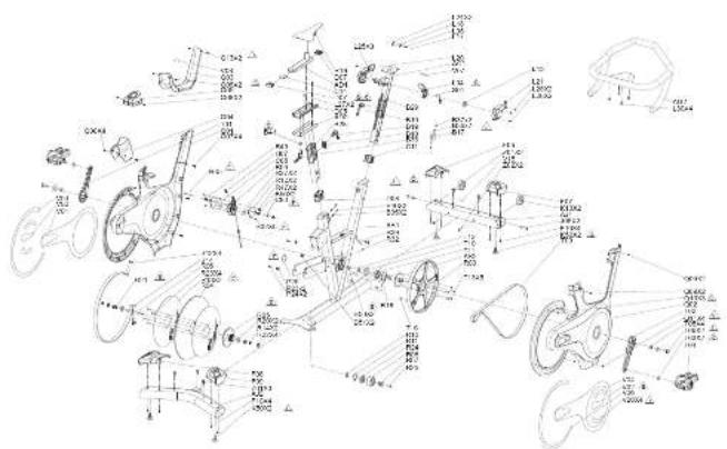
GR7S EXPLODED VIEW
text_image
Technical schematic diagram of a mechanical assembly with labeled components and dimensionsENGLISH
H215GR70FRsOWr1_0_Ained 30-31
GR7S PARTS LIST
| NO. DESCRIPTION QTY | NO. DESCRIPTION QTY | |||
| AR1 FRAME SPT 1 | L12 COVER,HANDI BREAD,RIGHT | 1 | ||
| B7 FASTEN PLATE 1 | L15 SWIVEL AXLE 1 | |||
| B6 LEAF SPRING 2 | L28 SCREW 2 | |||
| B7 SCREW 2 | L25 SCREW 5 | |||
| B9 PKLSSING BLOCK 1 | L05 SPRING | 1 | ||
| B10 KNDB 2 | L18 SPRING PIN | 1 | ||
| B2 CAP FRONT | 1 | L17 STEFL RAI | 1 | |
| B20 CAP BLOCK | 1 | L30 SCREW | 4 | |
| B42 SCREW 4 | L24 SCREW | 2 | ||
| B5 SPRING | 2 | C11 CAPCONSOLL MAST,COWN | 1 | |
| B40 SCREW 2 | L04 HANDLEBAR | 1 | ||
| B50 SCREW 2 | L27 SCREW | 2 | ||
| B51 NUT | 2 | C18 SCREW | 1 | |
| P23 TIE STRAP ADHRSIVE | 2 | A11 STABULIZER SET | 1 | |
| P24 SCREW 2 | J05 SCREW | 2 | ||
| P25 MOVEABLE BUSHING | II | A22 STABULIZER SET,BEAR | 1 | |
| S01 STEFL ROPE | 1 | K50 FOOT PAD | 4 | |
| AC1 CONSOLE MAX SET | 1 | K15 TRANSPORT WHEELS | 2 | |
| AC2 HANDLERAR | 1 | F06 CAP,RIGHT-FRONT | 1 | |
| L20 COVER,HANDLEBAR,LEFT | 1 | T07 CAP,LIFT-FRONT | 1 |

ENGLISH
3130
62/18 1:30 AM
GR7S PARTS LIST

| NO. | DESCRIPTION GTY | |
| F06 | CAP/LEFT-RFAD 1 | |
| F08 | CAP/BRIGHT-REAR 1 | |
| F10 | SCREW 8 | |
| AD1 | SEAT SLL/CVE SET 1 | |
| AD2 | SEAT PAD ADJUSTABLE SET 1 | |
| D05 | GUIDE BLOCK 1 | |
| R19 | SRAT PAD | 1 |
| D06 | CAP/DOWN | 1 |
| C14 | SNUG PLATE | 1 |
| B33 | KNOU | 1 |
| D07 | CAP/SEAT PAD/UP 2 | |
| B41 | WASHER | 1 |
| T18 | MAC/FT | 1 |
| R00 | DISK | 1 |
| T09 | BELT/POLY V | 1 |
| T04 | PECAL SET | 1 |
| T10 | BEARING | 1 |
| T11 | BEARING | 1 |
| T12 | SNAT RING | 1 |
| T13 | SCREW 5 |
| NO. | DESCRIPTION QTY | |
| R13 | FIX P. ATF | 2 |
| R04 | DISK | 1 |
| R05 | FIXING DISK | 1 |
| R06 | MAIN AXLL | 1 |
| R23 | BEARING | 2 |
| R21 | WASHER | 1 |
| R22 | ALT | 4 |
| R23 | SCRAW 6 | |
| R14 | WASHLR | 2 |
| R07 | AXLL OCLK | 1 |
| R08 | OLDER | 1 |
| R24 | BEARING | 1 |
| R28 | SCREW 1 | |
| R16 | SNAP RING | 1 |
| R11 | SWAP RING | 1 |
| T01 | CRANKL | 1 |
| T02 | CRANKR | 1 |
| T05 | SCREW SET | 2 |
| T05 | WASHER | 4 |
| R18 | SLAM | 1 |
| NO. | DESCRIPTION: QTY | |
| A32 | FEDAI MAIN AXI F-EXTRAWORK | 1 |
| B55 | PLASTIC LINER 2 | |
| H07 | SPRING | 1 |
| R39 | SPEED SENSOR WIDE | 1 |
| R31 | SCREW 4 | |
| R32 | SCREW 7 | |
| R39 | PLASTIC BACK 1 | |
| R12 | FIXING PLATE | 1 |
| C85 | POSITION AXLE 1 | |
| C93 | POSITION AXLE 1 | |
| R45 | SCREW 1 | |
| R35 | SCREW 1 | |
| R47 | NUT | 2 |
| R27 | POWERFUL MAGNET | 2 |
| C61 | SIDE COVERLEFT 1 | |
| C62 | COVERRIGHT 1 | |
| C63 | COVER FRONT 1 | |
| C64 | COVER BACK | 1 |
| C65 | COVER UP | 1 |
| C68 | SCREW | 5 |
| NO. | DESCRIPTION QTY | |
| Q09 | SCREW | 2 |
| Q07 | FIXING PILLAR | 4 |
| Q06 | SCREW | 2 |
| Q11 | SCROLL | 4 |
| Q13 | SCREW | 2 |
| Q18 | SCREW | 3 |
| V07 | DECAL HANDI REAR UP | 1 |
| V01 | DECALSIDE COVERLETT UP | 1 |
| V02 | DECALSIDE COVERLETT DOWN | 2 |
| V03 | DECALSIDE COVERLETT CLEAR | 1 |
| V04 | DECALSIDE COVERRIGHT UP | 1 |
| V05 | DECALSIDE COVERRIGHT REAR | 1 |
| V06 | WARNING LARE UP 1 | |
| V18 | EN LABEL | 1 |
| V20 | DECALSIDE COVER MIDDLE | 4 |
| Z01 | SCREW | 5 |
| Z03 | WRENCH | 1 |
| Z02 | SCREW | 2 |
| Z04 | WRENCH | 1 |
| V03 | SHIN | 2 |

INDOOR CYCLE NUTZUNG

DEUTECH
34
H2*8_GR7-0FwOW r1_0_Ained 34-36 B2715 11:30 AM

H215_GR7-GR7CNr1_0_Ained 38-Sr B2718 11:30 AM
WIE SIE DAS INDOOR CYCLE BEWEGEN SOLLEN
natural_image
Technical line drawing of a stationary bike with wheels and suspension components (no text or labels)Nivellierfüße

EINSTELLEN DES INDOOR CYCLE
natural_image
Technical line drawing of a stationary bike with suspension components (no text or labels)SATTELEINSTELLUNG
natural_image
Technical line drawing of a stationary bike with labeled components (no text or symbols beyond 'GR7' label)H215GR/CR/SOMr1_0_Ained 44-45 B2713 1130 AW
text_image
Technical diagram of a stationary exercise bike with labeled components and partstext_image
Technical diagram of a stationary bike with labeled components and dimensionsnatural_image
Line drawing of two exercise bikes in a seated position, no text or symbols presentMONTAGE ABGESCHLOSSEN!
GR7
H215GR/CRsCNr1_0_Ained 124382713 1135AW

HÄUFIGE FRAGEN ZUM PRODUKT
SIND DIE GERÄUSCHE, DIE MEIN Indoor Cycle MACHT, NORMAL?
H215_GR/CRsCNr1_0_Ained 545682718 1130 AN
FEHLERSUCHE
text_image
Technical schematic diagram of a vehicle's internal components and assembly, labeled with part numbers and technical annotations.
DEUTSCH
5756
DEUTSCH
H215GR/CR/SOMR_C_Ained 185762713 1130AW
GR7 TEILELISTE

HOSCH
| NR. | REACHRIFUNG VENGF | |
| AR1 | RAHMENFT | 1 |
| B17 | OFESTICUNGSP,ATTF,RAHIMEN,LINKS | 1 |
| B26 | LATTIFEDER,TORSION | 2 |
| B37 | SO-RAULE 2 | |
| B18 | FRESSELLOCK,RAHIMEN;RECHTS | 1 |
| B19 | OPPE | 2 |
| B14 | FFESTICUNGSP,ATTF | 1 |
| B29 | ADLOCKUNG,RAHIMEN;VORNE | 1 |
| B29 | ADLOCKUNG,RAHIMEN;HINTEN | 1 |
| B42 | SO-RAULE 4 | |
| B50 | EDLR | 2 |
| B40 | OHRALIBE 2 | |
| B50 | OHRALIBE 2 | |
| B51 | MUTTER | 2 |
| F23 | OPPFLISITIGES,KLEDGAND | 2 |
| F24 | OHRALIBE 2 | |
| F25 | DENEGILCHE BUCHSE | 0 |
| AC1 | KONSLENVMASTSET | 1 |
| C06 | FFESTICUNGSBASE,KNOPF | 1 |
| C08 | LICSTIGUNGSBLICK | 1 |
| ND | BESCHREIBUNG MENGIE | |
| A02 | 1 FINKER 1 | |
| L06 | TELLUNGSHAKEN | 1 |
| L06 | ARPOCKUNG | 1 |
| L21 | ADUCKUNG | 1 |
| B01 | STAHLSEL | 1 |
| L16 | PENBLACHGE | 1 |
| L24 | SCHRAUER 2 | |
| L25 | SCHRAUIC 7 | |
| L26 | SCHRAUIC 4 | |
| L28 | SCHRAUIC 2 | |
| L29 | SCHRAUIC 2 | |
| B26 | NP3 BEBESTIGUNGSGESTELL | 1 |
| C03 | RPPPSTICKINGSPATTF | 1 |
| C11 | KAPPE | 1 |
| B27 | RCSCELGROST | 1 |
| L05 | FEDER | 1 |
| L18 | FEDERSTIFT | 1 |
| L17 | STAHLKUGEL | 1 |
| B30 | NOTPS | 1 |
| B31 | SCHRUMPAD 1 |
| NR. BESCHREIBUNG MFNER | ||
| R29 SCHAIUMTAQ 1 | ||
| C15 FOSTES SCHNALLENSET 1 | ||
| L3H LENKER 1 | ||
| L27 SCHRAULIC 2 | ||
| B41 UTERLEOSCHEBE 2 | ||
| C16 SCHRAUBE 1 | ||
| R43 SCHAIUMTAQ 1 | ||
| AJ1 STADUSATORSET 1 | ||
| J09 SCHRAULIC 2 | ||
| AJ2 STADUSATORSET 1 | ||
| K00 FUSSPOLSTER 4 | ||
| K13 TRANSPORTRÄDER 2 | ||
| F08 KAPPE, VORNE RECHTS 1 | ||
| F07 KAPPE, VORNE LINKS 1 | ||
| F08 KAPPE, HINTEN LINKS 1 | ||
| F09 KAPPE, HINTEN RECHTS | ||
| F10 SCHRAUBE 8 | ||
| AO1 SATTTEL SCHLAUFENSET 1 | ||
| AO2 ANFASSARATE SITZVOL STERSET | ||
| D05 FORUNGSOLOCK 1 | ||
| N.2 SPESCHDRIBUNG MFNCF | ||
| R19 RITPOX STFR | 1 | |
| C08 APPE, UNTEN 1 | ||
| C14 OUSTESPLATTE | 1 | |
| U30 OPPE | 1 | |
| D07 APPE, OOLN | 2 | |
| R18 AUSCLICHESCHEBE | 1 | |
| R03 SCHBIEF | 1 | |
| T18 MAGNET | 1 | |
| T09 EVELN POLY V | 1 | |
| T04 FOLDSET LK 1 | ||
| T10 XGER | 1 | |
| T11 LAGER | 1 | |
| T12 SCHPRUNGSRING | 1 | |
| T01 WIRBEL L | 1 | |
| T02 WIRBEL R | 1 | |
| R13 BEFESTICUNGSPLATTE | 2 | |
| R04 SCHBIEF | 1 | |
| R05 BEFESTICUNGSICHEBE | 1 | |
| R06 HAUTACHSE | 1 | |
| R20 AGCH | 2 | |

DEUTRCH
5958
H215GR7CR7CNr10Alncl 1849
62718 1:30 AM
GR7 TEILELISTE

HOSCH
| NR. | FESCHTRIBUNG VENGE | |
| R21 | WATERLICOSCHERF 1 | |
| R22 | WUTTER 4 | |
| R23 | SCHKAURE 4 | |
| R14 | WITLERLICOSCHERF 2 | |
| R07 | ACHSE 1 | |
| R08 | WILENNICLE 1 | |
| R24 | AGER 1 | |
| R26 | SORRAUL 1 | |
| R10 | SCHNAPPRING C-FORM 1 | |
| R11 | SCHNAPPRING C-FORM 1 | |
| T00 | SCHRAUBENSET 2 | |
| T05 | WATERLICOSCHERF 4 | |
| AR2 | ALYTPFDIALACHSE 1 | |
| T13 | SORRAUL 3 | |
| R09 | KUNSTOFFGESTILL | 1 |
| R12 | BEESTIGUNGSPLATTE | 1 |
| R27 | STARKWABNET | 2 |
| B65 | KUNSTOFFFÜHRUNG | 2 |
| R45 | SCHKAURE 1 | |
| R47 | PUTTER 2 |
| ND. | RECHDRIBUNG MFGGE | |
| H07 | PROFB 1 | |
| R37 | RATTRIF | 1 |
| R38 | L23 | 1 |
| K09 | GLSCHWINDGKITSSENSORADEL | 1 |
| R41 | EATTERIESSOCKEL | 1 |
| R40 | MODUL, GRUPPE ANPASSAWER WIDERSTAND | 1 |
| R34 | REFESTIGUNGSRAUIS | 1 |
| R43 | PAFL SCHRAUF DOPPELSUTIR: | 1 |
| R31 | SCHRAUFE 4 | |
| K32 | SCHRAUFE 4 | |
| K32 | SCHRAUFE 3 | |
| C81 | POSITIONSACHSE | 1 |
| R35 | SCHRAUFE 1 | |
| C90 | POSITIONSACHSE | 1 |
| C01 | SEITE ABEDECKUNG LINKS | 1 |
| C02 | SEITE ABEDECKUNG RECHTS | 1 |
| C03 | ABEDECKUNG VORNE | 1 |
| C04 | ABEDECKUNG HINTEN | 1 |
| C05 | ABEDECKUNG OPEN | 1 |
| C07 | EUCSTIGUNGSSRAULE | 4 |
| NO. | BESCHREIBUNG MFGNEF | |
| Q68 | SCHRAURE | 8 |
| Q69 | SCHRAURE | 2 |
| Q68 | SCHRAURE | 2 |
| Q11 | SCHAUBE | 4 |
| Q13 | SCHAUBE | 2 |
| V01 | AUFALBER, SELTEN AROCKUNG, LINKS-OBEN | 1 |
| V02 | AUFALBER, SELTEN AROCKUNG, LINKS-UNTE | 1 |
| V03 | AUFALBER, SELTEN AROCKUNG, LINKS-HINTLN | 1 |
| V04 | AUFALBER, SELTEN AROCKUNG, RECHITS-OBEN | 1 |
| V06 | AUFALBER, SELTEN AROCKUNG, RECHITS-HINTLN | 1 |
| V07 | AUFALBER, LINKER, OGEN | 1 |
| V08 | WAINAURK, EFRP, CBFN | 1 |
| V15 | FINAURK EFRP | 1 |
| V26 | AUFALBER, SELTEN AROCKUNG, MITTEL | 4 |
| Z01 | SCHAUBE | 6 |
| Z03 | SCHRAUBENSCHLÖSSEL | 1 |
| Z02 | SCHAUBE | 2 |
| Z04 | SCHRAUBENSCHLÖSSEL | 1 |
| T03 | AUSOL FICHSCHEBE 2 |
H215GR70FRsOWr1_0_Ained 50-81

DEUTSCH
6160
62718 1:30 AM

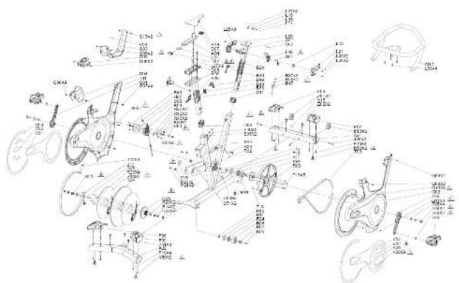
GR7S EXPLOSIONSANSICHT
text_image
Technical schematic diagram of a mechanical assembly with labeled components and dimensionsDEUTSCH
H215GR/CR/SOMR_C_AIncl 5283
GR7S TEILELISTE
| NO. | BESCHRIFÜNC MENCFE | NO. | BESCHRIFÜNC MENCFE | |||
| A31 | TÄRMENSET 1 | I 21 | ARDEKLINC LENKFÖ RECHTS | 1 | ||
| B17 | BEFESTGUNGSPATTE 1 | L15 | PENDELACHBE 1 | |||
| B38 | BLATTFEDER 2 | L28 | SCHRAUBE 2 | |||
| B37 | SCHRAUBE 2 | L25 | SO RAUDE 5 | |||
| B19 | PHLISDBLOCK 1 | L05 | PEDER 1 | |||
| B16 | NOPPE 2 | L18 | FEDERSTIFT | 1 | ||
| B20 | KAPPE VOONE 1 | L17 | STAHI KUGEL | 1 | ||
| B20 | KAPPE HINTLN 1 | L30 | SO RAUDE 4 | |||
| B42 | SCHRAUBE 4 | L24 | SO RAUDE 2 | |||
| B36 | FLÜDK 2 | C11 | KAPPE KONSOLLENMAST UNTLN | 1 | ||
| B40 | SCHRAUBE 2 | L04 | LENNER | 1 | ||
| B50 | SCHRAUBE 2 | L27 | SCHRAUBE 2 | |||
| B51 | VUTTF2 2 | C18 | SCHRAUBE 1 | |||
| P23 | DOFPSELSETIGES KLEBEDAND 2 | A17 | STABILISATORSET | 1 | ||
| P24 | SCHRAUBE 2 | J06 | SCHRAUBE 2 | |||
| P26 | BEVEGLICHE BUCHSE | 0 | A22 | STABILISATORSET, HINTEN | 1 | |
| S01 | STAHLSPIL | 1 | K50 | RASSPOLSTER | 4 | |
| AC1 | KONSOLLENMASTSET | 1 | K13 | TRANSPORTRADER | 2 | |
| A02 | LENNER | 1 | F08 | KAPPE VOONE RECHTS | 1 | |
| L02 | ABDCRUNS:LENNER:LINKS | 1 | T07 | KAPPE VOONE LINKS | 1 |

DEUTRCH
6362
62/18 1:30 AM
GR7S TEILELISTE
| X |
| DEUTSCH |
| NR. BESCHRIFÜRG MÄNGE | |
| F06 KAPPE; HINTENLINKS | 1 |
| F06 KAPPE; HINTENRECHTS | 1 |
| F10 SCHRAUFE | 6 |
| AD1 BATLLSD LAUF CNBLT | 1 |
| AD2 ANPASSBARES SITZPOLSTERSET | 1 |
| D05 FÜRTUNGSBLOCK | 1 |
| D10 SITZPO. STER | 1 |
| D09 KAPPE; UNTEN | 1 |
| C14 POLSTERPLATTE | 1 |
| D33 NOFFLE | 1 |
| D07 KAPPE; SITZPOLSTER; OJEN | 2 |
| B41 UNTERLEGSCHEIBE | 1 |
| T16 MAGNET | 1 |
| R03 SCHEIBE | 1 |
| T06 RICEMEN; POLY V | 1 |
| T04 PEDALSET | 1 |
| T10 LAGER | 1 |
| T11 LAGER | 1 |
| T12 SICHERUNGSRING | 1 |
| T13 SCHRAUFE | 5 |
| NR. BESCHREBUNG MENGE | |
| R13. EFFESTICUNIGER ATTF 2 | |
| R34. SCHEBE | 1 |
| R35. EFFESTICUNIGSCHERF | 1 |
| R36. HUPTACHSL | 1 |
| R20. LAGER 2 | |
| R21. UNTERLIGSCHERFE | 1 |
| R22. LUTTER 4 | |
| R23. SCHRAUCEL 4 | |
| R14. UNTERLIGSCHICUE | 2 |
| R37. CHISC. TÜH MUNG | 1 |
| R38. UMLEVKROLLE | 1 |
| R24. LAGER 1 | |
| R26. SCHRAUPE 1 | |
| R10. SCHERUNSGRING | 1 |
| R11. SCHERUNSGRING | 1 |
| T81. KURBEL, 2 | 1 |
| T82. KURBEL, 3 | 1 |
| T85. SCHTALIBENSET | 2 |
| T85. UNTERLIGSCHERF | 4 |
| R16. AUSGLICISCHILDS | 1 |
| NR. BESCHREIBUNG MENOR | |
| A29 PDAI FINHAUPTACHSF-EXTRAARBIT 1 | |
| B28 KUNSTSTOFFDIIRUNG 2 | |
| H27 FEDER 1 | |
| R39 GLCCHWINDIGRELITSSONSOKAULL 1 | |
| R31 SCHRAUBE 4 | |
| R32 SCHRAUBE 7 | |
| R39 KUNSTSTOFFOPSTILL 1 | |
| R12 GLCFSTRUKNSPLATTE 1 | |
| C30 POSITIONSACI-SC 1 | |
| C33 POSITIONSACI-SC 1 | |
| R40 SCHRAUBE 1 | |
| R35 SCHRAUBE 1 | |
| R47 MUTTER 2 | |
| R27 STARKMAGNET 2 | |
| C01 SEITE ABDECKUNG LINKS 1 | |
| C02 ABDECKUNG RECHTS 1 | |
| C03 ABDECKUNG VORUR | 1 |
| C04 ABDECKUNG HINTEN | 1 |
| C05 ABDECKUNG ORN | 1 |
| C09 SCHRAUBE | 0 |
| N.3 | FISCHDRIBUNG, MFNCF | |
| O08 | SCHRAUBE | 2 |
| O07 | DEFENGLUNGSRALE | 4 |
| O06 | SCHRAUBE | 2 |
| O11 | SCHRAUBE | 4 |
| O13 | SCHRAUBE | 2 |
| O10 | SCHRAUBE | 3 |
| V07 | ALFKLERB, LINKRD, OBN | 1 |
| V01 | AUFILDECK SELTEN ABDECKUNG; LINKS-OBN | 1 |
| V02 | AUFILDECK SELTEN ABDECKUNG; LINKS-UNTEN | 2 |
| V03 | AUFILDECK SELTEN ABDECKUNG; LINKS-HINTEN | 1 |
| V04 | AUFILDECK SELTEN ABDECKUNG; RECHTS OBN | 1 |
| V06 | AUFLEBER, SELTEN ABDECKUNG; RECHTS-HINTEN | 1 |
| V08 | VANVAUKKI FRR, OBN | 1 |
| V15 | VANFAUKLEBER 1 | |
| V20 | AUFLEBER, SELTEN ABDECKUNG; MITTE | 4 |
| Z01 | SCHRAUBE | 5 |
| Z03 | CHRAURWISCH ÖSSRI | 1 |
| Z02 | SCHRAUBE | 2 |
| Z04 | CHRAURWISCH ÖSSRI | 1 |
| T03 | KUGLOCHISSCIJELIE | 2 |
| X |
| DEUTCH |
| 6564 |
BEDIENING VAN DE INDOORFIETS

NEDERLANDS
H215_GR7-GR7CNr1_0_Ained 58-87 62713 1130 AW

BELANGRIJKE VEILIGHEIDSINSTRUCTIES BEWAAR DEZE INSTRUCTIES LEES ALLE INSTRUCTIES VOORDAT U DEZE FITNESSAPPARATUUR GEBRUIKT.
H215GR/CRsCNr1_0_Ained 58.69 82713 1135 AW
DE INDOORFIETS VERPLAATSEN
natural_image
Technical line drawing of a stationary bike with labeled components and motion arrows (no text or symbols)Stelvocelen
NEDERLANDS
6968

DE INDOORFIETS AFSTELLEN
natural_image
Technical line drawing of a stationary bike with suspension components (no text or labels)ZADELAFSTELLING
natural_image
Technical line drawing of a stationary bike with labeled components (no text or symbols beyond 'GR7' label)OM DE ZADELHOOGTE AAN TE PASSEN:
H215GR/CRsCNr1_0_Ained 72-382718 1135AW
WEERSTANDSCONTROLE EN NOODREM
H2*8_GR7-0FwCNr1_0_Ained 74-75 B2715 11:30 AM
MONTAGE
WAARSCHUWING
text_image
Technical diagram of a stationary exercise bike with labeled components and parts
H215GR/CR/SOMr1_0_Ained 267982713 1135AW
HZ18_GR2-GR7-CN r1_0_Ained 50-61 B2718 1135 AW

MONTAGE STAP 3 (GR7)
NEDDERLANDS
text_image
Technical diagram of a stationary bike with labeled components and measurement annotationsnatural_image
Line drawing of two exercise bikes in a seated posture, no text or symbols presentMONTAGE VOLTOOID!
GR7
Afmetingen: 134 x 56,2 x 105,8 cm / 53" x 22" x 42"
Productgewicht: 51 kg / 112 lbs
H215GR/CR/SOMn1_0_Ained 628382718 1135AW
PROBLEEMOPLOSSING EN ONDERHOUD

NEDERLANDS
84
H215_GR/GR/SW n1_0_Ained 14-85 B2713 11:30 AM

VEELGESTELDE PRODUCTVRAGEN
ZIJN DE GELUIDEN DIE MIJN indoorfiets MAAKT NORMAAL?
H215_GR/CRsCNr1_0_Ained 18-87-92718 11:30 AM
PROBLEEMOPLOSSING
text_image
Technical schematic diagram of a mechanical assembly with labeled components and assembly details
ONDERDELENLIJST VAN GR7

NEDERLANDS
| NR. | RECHTLIVING AANTAL | |
| AR1 | FRAMFSET | 1 |
| B17 | DEVSTGINGSPILAT, FRAME, LINKS | 1 |
| B26 | RADWER, TOSSIE | 2 |
| B37 | SO-ROLL 2 | |
| B18 | PERSBLOK, FRAME, RECHTS | 1 |
| B19 | HOP | 2 |
| B14 | RVSSTGINGSPILAT | 1 |
| B29 | RAP, TRAVEL, VOGRAN | 1 |
| B29 | RAP, TRAVEL, ACITERMAN | 1 |
| B42 | SO-ROLL 4 | |
| B50 | VIER | 2 |
| B40 | CHROEF 2 | |
| B50 | CHROFF 2 | |
| B51 | NOER | 2 |
| F23 | SINGKLLEEFVIDDEL | 2 |
| F24 | CHROEF 2 | |
| F25 | DENEDGBARE LAGERBUS | 0 |
| AC1 | CONSOLEMASTSET | 1 |
| C06 | VONTAGEVORT, KNOP | 1 |
| C08 | ELEVISTINGSVBLOK | 1 |
| NR. | BEACHRYING AANTAL | |
| A02 | STJUR 1 | |
| L06 | POSTIEHAAK | 1 |
| L06 | ATDKUNG | 1 |
| L21 | OLKUNG | 1 |
| B01 | STAUKABEL | 1 |
| L16 | DRAAAS | 1 |
| L24 | SCHROFF 2 | |
| L26 | SCHROFF 7 | |
| L26 | SCHROFF 4 | |
| L28 | SCHROFF 2 | |
| L29 | SCHROFF 2 | |
| B26 | NP3-HOLDER | 1 |
| C03 | REVISTIGNOSPI AAT | 1 |
| C11 | KAP | 1 |
| B27 | DRINKUSHOUOER | 1 |
| L00 | VEER | 1 |
| L18 | VEERPEN | 1 |
| L17 | STALEN KOCEL | 1 |
| B36 | NGDP | 1 |
| B31 | SCHUMKUSSLN 1 |
| NR. BESCHLIVING AANTAL | |
| R29 SCHUMMUSSEN 1 | |
| C15 DESPLUTINGSET 1 | |
| L34 STUUR 1 | |
| L27 SCHROEF 2 | |
| B41 SLUTRING 2 | |
| C16 SCHROEF 1 | |
| R43 SCHUMMUSSEN 1 | |
| AJ1 STADILATORSET 1 | |
| J09 SCHROEF 2 | |
| AJ2 STADILATORSET 1 | |
| K20 VOLTSTELN 4 | |
| K13 TRANSPORTWIELEN 2 | |
| F08 KAP, RECHTS VOORAN 1 | |
| F07 KAP, LINKS VOORAN 1 | |
| F08 KAP, LINKS ACHTERAN | 1 |
| F09 KAP, RECHTS ACHTERAN | 1 |
| F10 SCHROFF 3 | |
| AO1 ZADELHOBSSET | 1 |
| AO2 APSTEIR AARF ZITKLUSSPENSET | 1 |
| DO5 BELLODBLOR | 1 |
| N.1 BESCHRIJVINC AANTAI | |
| R192 TUKUSSPN | 1 |
| D08 RAP, BENEDEN | 1 |
| C14 ANIS, MITTAAT 1 | |
| U33 RYOP | 1 |
| D07 RAP, BOVEN 2 | |
| R18 NUPLAATJE | 1 |
| R03 SCHUF | 1 |
| T18 MAGNLCT 1 | |
| T09 S LCV, POLY V | 1 |
| T04 FLOWALSET, LM | 1 |
| T10 YGER | 1 |
| T11 LAGER | 1 |
| T12 MORCRING | 1 |
| T01 CRAK, L | 1 |
| T02 CRAK, R | 1 |
| R13 BEVESTIGNGSPLAAT | 2 |
| R04 SCHUF | 1 |
| R05 BEVESTIGNGSCHUF | 1 |
| R06 HOOFAS | 1 |
| R20 AGCR 2 |

NEDERLANDS
9190
H215GR7CR7CNWrt_0_Ained 20.01
62/18 1:30 AM
ONDERDELENLIJST VAN GR7

NEDERLANDS
| NR. FESCHTIVING AANTAI | ||
| R21 5 LUITRING | 1 | |
| R22 VOER | 4 | |
| R23 SCHROFF 1 | ||
| R14 SLUITRING | 2 | |
| R07 AS | 1 | |
| R08 SPANROL 1 | ||
| R24 LADER | 1 | |
| R28 SCHROFF 1 | ||
| R18 ODRIGING, CAVORING | 1 | |
| R11 ODRIGING, CAVORING | 1 | |
| T06 SCHROVELNSST | 2 | |
| T05 LUITRING | 4 | |
| AR2 HOOFIAS PEDALI | 1 | |
| T12 SCHROFF 5 | ||
| R00 PLASTIC RELK | 1 | |
| R12 BEVESTIGINGSLAAT | 1 | |
| R27 PRACHTISE MAGNEET | 2 | |
| B69 PLASTIC VOERING | 2 | |
| R45 SCHROFF 1 | ||
| R47 POLCR | 2 | |
| NR | FESCHRIJING AANTAL | |
| H07 | FER | 1 |
| R37 | ACU | 1 |
| R36 | IC8 | 1 |
| K09 | SNCU EDSSUSGORKNJLL | 1 |
| R41 | COUBASIS | 1 |
| R40 | MODULIE, VARIABLE WEERSTAVDSGROEP (VR) | 1 |
| R51 | MONTAGEVOET | 1 |
| H03 | APL SCUM, TWELDUG | 1 |
| K31 | SCHROEF 4 | |
| K32 | SCHROEF 4 | |
| K32 | SCHROEF 3 | |
| C81 | POSITIFAS | 1 |
| R35 | SCHROFF 1 | |
| C90 | POSITILAS | 1 |
| C01 | JAFDEEKING, LINKS | 1 |
| C02 | JAFDEEKING, RECHTS | 1 |
| C03 | JAFDEKING, VOORAN | 1 |
| C04 | JAFDEKING, ADTERAN | 1 |
| C05 | JAFDEKING, ROVENAN | 1 |
| C07 | JLVSTKGKGSSTANG | 4 |
| NO. | BESCHRIJING, AANTAL | |
| 068 | SCHROFF 8 | |
| 069 | SCHROFF 2 | |
| 068 | SCHROFF 2 | |
| 011 | SCHROFF 4 | |
| 013 | SCHROFF 2 | |
| V01 | STICKER, ZUAFDERKING, LINKSROVEN 1 | |
| V02 | STICKER, ZUAFDERKING, LINKSROVER 2 | |
| V03 | STICKER, ZUAFDERKING, LINKSADITLER 1 | |
| V04 | STICKER, ZUAFDERKING, RECHTSROVEN 1 | |
| V05 | STICKER, ZUAFDERKING, RECHTSADITLER 1 | |
| V07 | STICKER, STUK, ROVEN 1 | |
| V08 | WAARSHOWINGSLABEL ROVEN 1 | |
| V15 | LABEL RIV 1 | |
| V20 | STICKER, ZUAFDERKING, MIDCOLN 4 | |
| Z01 | SO-ROCEF 5 | |
| Z03 | MOERSLEUTEL | 1 |
| Z02 | SO-ROCEF 2 | |
| Z04 | MOERSLEUTEL | 1 |
| T03 | VULP-LAATF | 2 |

NEDERLANDS
93
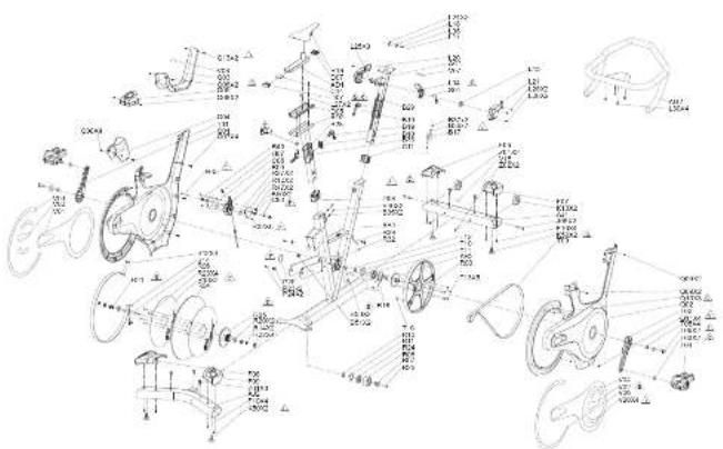
OPENGEWERKTE TEKENING VAN GR7S

text_image
Technical schematic diagram of a mechanical assembly with labeled components and dimensionsNEDERALDOS
H215GR7CR7CNr10Alncel 34.95
ONDERDELENLIJST VAN GR7S
| NB: BESCHRIJVING AANTAL | NB: BESCHRIJVING AANTAL | |||
| A81 FRANKFET 1 | I 21 AFDERKING STUDUR, RECHTS | 1 | ||
| B17 BEVESTIGINGRIP, AAT 1 | L15 DRAAKS | 1 | ||
| B36 BI KAVFER 2 | L28 SCHROEF 2 | |||
| B37 SCHROEF 2 | L25 SCHROEF 5 | |||
| B19 PECKSELOK 1 | L05 VLDH 1 | |||
| B18 KNCP 2 | L18 VERIPEN | 1 | ||
| B20 KAT, VOOGAAN 1 | L17 STAI EN KOOFL | 1 | ||
| B20 KAP, ACHTERAAN 1 | L30 SCHROEF 4 | |||
| B42 SCHROEF 4 | L24 SCHROEF 2 | |||
| B39 VLDH 2 | C11 AP CONSOLLMAST, ONDLRVAN | 1 | ||
| B40 SCHROEF 2 | L04 STUDUR | 1 | ||
| B50 SCHROEF 2 | L27 SCHROEF 2 | |||
| B51 WOFER 2 | C18 SCHROFF 1 | |||
| P23 SINGELKLEEFMODEL 2 | A17 STABILISATORSET | 1 | ||
| P24 SCHROEF 2 | J06 SCHROEF 2 | |||
| P26 BEVEEGBARE LAGERBUS | 0 | A22 STABILISATORSET, ACHTERAAN | 1 | |
| SO1 STAALXAREL | 1 | K50 VDETSTFUN | 4 | |
| AC1 CONSOLEMASTSET | 1 | K13 TRANSPORTWIELEN | 2 | |
| A02 STJUR | 1 | F08 AP, RECHTS VOOGAAN | 1 | |
| L02 AF DECKING, STUDUR, LINKS | 1 | T07 AP, LINKS VOOGAAN | 1 |

NEDERLANDS
9594
62/18 1:30 AM
ONDERDELENLIJST VAN GR7S

NEDERLANDS
| NR. BESCHTLIVING AANTAL | |
| F06 KAP, LINKS ACHTERAAN | 1 |
| F06 KAP, RECHTS ACHTERAAN | 1 |
| F10 SCHROFF | 8 |
| AD1 ZÄDLLIKOLSET | 1 |
| AD2 AFSTELBARE ZITKUSSENET | 1 |
| D05 GELRIDEBLOK | 1 |
| D10 ZITKUSSEN | 1 |
| D09 KAP, JONDCN | 1 |
| C14 AWNSLUTPLAT | 1 |
| E33 ROP | 1 |
| D07 KAP, ZITKUSSEN, BOVENAN | 2 |
| B41 SLUTRING 1 | |
| T16 MAGNFT 1 | |
| R03 SCHUF | 1 |
| T06 ROM POLY V | 1 |
| T04 PEDALSET | 1 |
| T10 LAGER | 1 |
| T11 LAGER | 1 |
| T12 ROTGING | 1 |
| T13 SCHROFF | 5 |
| NR. BESCHLIVING AANTAL | |
| R13. RIVFETIONGSPLAAT 2 | |
| R34. SCHLF | 1 |
| R35. RIVFETIONGSICHLF | 1 |
| R36. COD DAS | 1 |
| R20. LAGER | 2 |
| R21. SLUITRING | 1 |
| R22. MOFF 4 | |
| R23. SCIROLD 4 | |
| R14. SLUITRING | 2 |
| R31. AS, SPANKOL | 1 |
| R38. SPANKOL | 1 |
| R24. LAGER | 1 |
| R26. SCHRDEF 1 | |
| R10. DOCKRING | 1 |
| R11. DOCKRING | 1 |
| T01 CRANK L | 1 |
| T02 CRANK R | 1 |
| T05. GCHRCVENSET | 2 |
| T05. R. SLUITRING 4 | |
| R16. V. PLATAATC | 1 |
| NR. BESCHRYING, AANTAL | |
| A72 HOOFNAS PRAAL-FXTRAWORK 1 | |
| B98 PLASTIC VOERING 2 | |
| H07 VFFR 1 | |
| K09 SALLI DISSLSVSRKAJEL 1 | |
| K31 SCHROEF 4 | |
| K32 SCHROEF 7 | |
| R09 P ASTIC OFK 1 | |
| H12 BLVCSTIGINGSPLAT 1 | |
| C30 POSTILAS 1 | |
| C33 POSTILAS 1 | |
| R45 SCHROEF 1 | |
| R35 SCHROEF 1 | |
| R47 MOFR 2 | |
| R27 KRAC-THICE MAGNET 2 | |
| C01 Z-AFDEKING, LINKS | 1 |
| C02 AFDEKING, RED-TS | 1 |
| C03 AFDEKING, VOERAN | 1 |
| C04 AFDEKING, ADTERAN | 1 |
| C05 AFDEKING, ROVENAN | 1 |
| C09 SCHROEF | 0 |
| N/A SPCHIRUVINC AANTAI | ||
| Q06 SCHROFF | 2 | |
| Q07 EVOSTIONKSISTANG | 4 | |
| Q08 SCHROFF | 2 | |
| Q11 SCHROLF | 4 | |
| Q13 SCHROLF | 2 | |
| Q16 SCHROFF | 3 | |
| V07 STICKR, STUDI. BOVEN | 1 | |
| V01 STICKR, ZAM DEKKING, LINKSBOVEN | 1 | |
| V02 STICKR, ZAM DEKKING, LINKSUNDER | 2 | |
| V03 STICKR, ZAM DEKKING, LINKSACHTER | 1 | |
| V04 STICKR, ZAMDEKKING, RECHTSBOVEN | 1 | |
| V05 STICKR, ZAMDEKKING, RECHTSACHTER | 1 | |
| V06 VAARSCHUMINGSI ARRI. BOVEN | 1 | |
| V15 RABELN | 1 | |
| V20 STICKR, ZAMDEKKING, MIDDEN | 4 | |
| Z01 SCHROFF | 6 | |
| Z02 OFRSI FUTRI | 1 | |
| Z02 SCHROFF | 2 | |
| Z04 OFRSI FUTRI | 1 | |
| TZ3 MULPLATIE | 2 | |

NEDERLANDS
9796
H215GR7CR7CNr10Alncel 38-97
62/18 1:30 AM
FONCTIONNEMENT DU VÉLO D'APPARTEMENT

FRANCIER
H215GR/GRwCNrl_0_Ained 16-9982713 11:30 AM

INSTRUCTIONS DE SÉCURITÉ IMPORTANTES - VEUILLEZ CONSERVER CES INSTRUCTIONS VEUILLEZ LIRE TOUTES LES INSTRUCTIONS AVANT D'UTILISER CET APPAREIL D'EXERCICE.
H215GR7CR7CNr1_0_Ained 100-10182718 11:30 AM
COMMENT DÉPLACER LE VÉLO D'APPARTEMENT
natural_image
Technical line drawing of a stationary bike with wheels and suspension components (no text or symbols)natural_image
Technical line drawing of a stationary bike with suspension components (no text or labels)RÉGLAGE DE LA SELLE
natural_image
Technical line drawing of a stationary bike with labeled components (no text or symbols beyond 'GR7' label)H215GR/CR/SOM1_0_Ained 104-10s 82718 11:30 AM
CONTRÔLE DE LA RÉSISTANCE ET FREIN D'URGENCE
text_image
Technical diagram of a stationary exercise bike with labeled components and assembly parts
H215GR/CFM CN r1_0_Ained 110-11182718 11:30 AM
text_image
Technical diagram of a stationary bike with labeled components and measurement annotationsnatural_image
Line drawing of two exercise bikes in a seated position, no text or symbols presentLE MONTAGE EST TERMINÉ !
GR7
Dimensions: 134 x 56.2 x 105.8 cm (53" x 22" x 42")
QUESTIONS FRÉQUENTES RELATIVES AU PRODUIT
text_image
Technical schematic diagram of a mechanical assembly with labeled components and assembly details
FRANCY
121120
H215GR/CR/SOM1_0_Aincl 120-12182718 11:30 AM
LISTE DES PIÈCES GR7

FRANÇAIS
| No | DESCRIPTION. QTE | |
| A61 | CADRE | 1 |
| B17 | FLAQUE DE SERRADE, CADRE ; GAUCHE | 1 |
| B38 | FESSORT À LAVE, TORSION | 2 |
| B57 | VIS 2 | |
| B18 | LOCAGE AVOC PRESSION; CADRE ; DROIT | 1 |
| B19 | BOUTON | 2 |
| B14 | FLAQUE DE FIXATION | 1 |
| B29 | CAPUCHON ; CADRE ; AVANT 1 | |
| B29 | CAPUCHON ; CADRE ; ARRÊNE | 1 |
| B42 | VIS 4 | |
| B30 | FESSORT | 2 |
| B40 | VIS 2 | |
| B50 | VIS 2 | |
| B51 | CROU | 2 |
| F23 | GOURSOIL D'ATTACHE ADHESIVE | 2 |
| F24 | VIS 2 | |
| F25 | BAQUE AMOVIBLE | € |
| AC1 | ENSEMBLE DE SUPPORT DE CONSOLE | 1 |
| C06 | BOCLE DE FIXATION , BOUTON | 1 |
| C08 | BLIC DE FIXATION | 1 |
| No | DESCRIPTION QTE | |
| A02 | GUIDON 1 | |
| L06 | RIOCKET D'EMPLACEMENT | 1 |
| L09 | ACHE | 1 |
| L21 | ACHE | 1 |
| B07 | CABLE D'ACIER | 1 |
| L15 | AXE PIVOTANT | 1 |
| L24 | VS 2 | |
| L25 | VS 7 | |
| L26 | VS 4 | |
| L28 | VS 2 | |
| L29 | VS 2 | |
| B26 | CLISSIERE DE SUPPORT MP3 1 | |
| C03 | PLAQUF DE SERRACE | 1 |
| C11 | APUCHON | 1 |
| B27 | SUPPORT DE ROUTILLE | 1 |
| L08 | RESSORT | 1 |
| L18 | COUPLLE A RESSORT | 1 |
| L17 | BILLE EN ACIER | 1 |
| B30 | SOUTON | 1 |
| B31 | HMGOURVAGE EN MGRUSSE 1 |
| No DESCRIPION OTE | |
| B32 RENBOURRAGE EN MOUSSE 1 | |
| C15 ENSEMBLE DE BOUCLE DE FIXATION 1 | |
| L34 GUIDON 1 | |
| L27 VIS 2 | |
| B41 RONCELLE 2 | |
| C16 VIS 1 | |
| B43 RENBOURRAGE EN MOUSSE 1 | |
| AJ1 ENSEMBLE DE STABILISATEUR 1 | |
| J09 VIS 2 | |
| AJ2 ENSEMBLE DE STABILISATEUR 1 | |
| K30 REPOSE-PIEDS 4 | |
| K13 ROULETTES DE TRANSPORT 2 | |
| F08 CAPUCHON ; AVANT DROIT 1 | |
| F07 CAPUCHON ; AVANT GAUCHE 1 | |
| F09 CAPUCHON ; ARRIERE GAUCHE | 1 |
| F09 CAPUCHON ; ARRIERE DROIT | 1 |
| F10 VIS 5 | |
| AD1 ENSEMBLE DE MANCHON DE SELLE | 1 |
| AD2 ENSEMBLE RECLABLE DE COUSSIN DE SIBGE | 1 |
| DOS BLOC DE GUIAAGE | 1 |
| No. | DESCRIPTION CTE | |
| R10 | COLSIN DU SIRGE | 1 |
| D08 | APUCHON; INFÉRIEUR | 1 |
| C14 | FLAQUE AERGOT | 1 |
| U33 | OUYON | 1 |
| D07 | APUCHON; SUPERHEUR | 2 |
| R18 | CALE | 1 |
| R03 | DISQUE | 1 |
| T16 | AMANT | 1 |
| T08 | POUNICIL; POLY-V | 1 |
| T04 | INTELUL DE PECALER, IS-D | 1 |
| T10 | POULEMENT | 1 |
| T11 | POULEMENT | 1 |
| T12 | RAGUE ELASTIQUE | 1 |
| T01 | EDALER (G) | 1 |
| T02 | EDALER (O) | 1 |
| R13 | FLAQUE DE FIXATION | 2 |
| R04 | DISQUE | 1 |
| R05 | DISQUE DE FIXATION | 1 |
| R06 | AR PRINCIPAL | 1 |
| T20 | POULEMENT | 2 |

FRANCIS
123122
LISTE DES PIÈCES GR7

FRANÇAIS
| No | DESCRIPTION OTE | |
| R21 | RONCELLE | 1 |
| R22 | SOROU | 4 |
| R23 | RIS 4 | |
| R14 | RONCELLE | 2 |
| R07 | OSIEU | 1 |
| R08 | TENDEUR | 1 |
| R24 | POUL EVENT | 1 |
| R28 | RIS 1 | |
| R10 | AGUE ELASTIQUE : EN FORME DE C | 1 |
| R11 | AGUE ELASTIQUE : EN FORMA DE C | 1 |
| T06 | ENSEMULE DE VIS | 2 |
| T05 | RONCELLE | 4 |
| AR2 | AXE PRINCIPAL DE RÉDALE | 1 |
| T13 | VIS 2 | |
| R09 | SUPPORT EN PLASTIQUE | 1 |
| R12 | FLACQUE DE FIXATION | 1 |
| R27 | AMANT PUESANT | 2 |
| B65 | REVOURRAGE EN PLASTIQUE | 2 |
| R45 | RIS 1 | |
| R47 | SOROU | 2 |
| No | DESCRIPTION QTE | |
| H07 | FESSORT. | 1 |
| R37 | BATTERIE | 1 |
| R56 | LC8 | 1 |
| K98 | CABLE DE CAPTEUIL DE VITELSSE | 1 |
| R41 | BASE DE BATTERIE | 1 |
| R40 | MODULE ; GROUPE DE RESISTANCE VARIABLE VR | 1 |
| E54 | BOCLE DE FIXATION | 1 |
| R43 | HUAN ; MOUSSIL DILUX CÔTUS ; | 1 |
| R31 | VS 4 | |
| R32 | VS 4 | |
| R32 | VS 3 | |
| C83 | AXE DE POSITIONNEMENT | 1 |
| R35 | VS 1 | |
| C86 | AXE DL POSITIONNEMENT | 1 |
| C81 | CACHE LATERIAL ; GAUCHE | 1 |
| C82 | CACHE LATERIAL ; CRIGHT | 1 |
| C83 | CACHE ; AVANT | 1 |
| C84 | CACHE ; ARRIERE | 1 |
| C85 | CACHE ; SUPERFUR | 1 |
| C87 | MONTANT DE FIXATION | 4 |
| No. | DESCRIPTION QTE | |
| C08 VIS 8 | ||
| C09 VIS 2 | ||
| C10 VIS 2 | ||
| C11 VIS 4 | ||
| C12 VIS 2 | ||
| V01 ETICUETTE, CACHE LATERAL ; SUPEREUR CAUCHE 1 | ||
| V02 ETICUETTE, CACHE LATERAL ; SUPEREUR CAUCHE 2 | ||
| V03 ETICUETTE, CACHI LATERAL ; ARRÈRE BAUCHE 1 | ||
| V04 ETICUETTE, CACHI LATERAL ; SUPEREUR DROIT 1 | ||
| V05 ETICUETTE, CACHI LATERAL ; ARRÈRE DROIT 1 | ||
| V07 ETICUETTE ; GUIDON ; SUPERÉUR 1 | ||
| V08 ETICUETTE D'AVERTISSEMENT ; SUPERÉUR 1 | ||
| V15 ETICUETTE EN 1 | ||
| V20 ETICUETTE, CACHI LATERAL ; VILLCU 4 | ||
| Z01 VIS 5 | ||
| Z03 CLE | 1 | |
| Z02 VIS 2 | ||
| Z04 CLE | 1 | |
| T03 CA.E | 2 |
H2:5_GR/GE/SWn1_0_Ainol 124-125

FRANCIS
125124
62718 1:30 AM
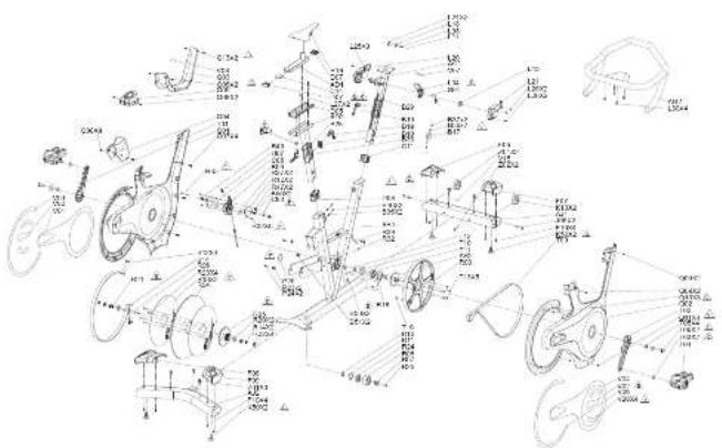
VUE ÉCLATÉE DU MODÈLE GR7S

text_image
Technical schematic diagram of a mechanical assembly with labeled components and dimensionsFRANÇAIS
H2:5_GR/CFwOWrl_0_Ained 128-127
LISTE DES PIÈCES GR7S
| No DESCRIPTION QTE | No DESCRIPTION QTE | ||
| A81 CADRE 1 | L21 CACHE : GUIDON DROIT | 1 | |
| B17 PLAQUE DE SETRAGE 1 | L15 AXE PHOTANT | 1 | |
| B36 RESSORT À LANE 2 | L26 VIS 2 | ||
| B37 VIS 2 | L25 VIS 5 | ||
| B18 SLOCARE AVEC PRESSION 1 | L05 HLGSOCK 1 | ||
| B19 BOUTON 2 | L18 COUPILE À RESSORT | 1 | |
| B20 CAPUCHON : AVANT 1 | L17 BLLE EN ACIER | 1 | |
| B20 CAPUCHON : AVIDUL 1 | L30 VIS 1 | ||
| B42 VIS 4 | L24 VIS 2 | ||
| B38 HLGSOCK 2 | C11 CAPUCHON : MONTANT DELA CONSULE INTÉRIEUR | 1 | |
| B40 VIS 2 | L04 GUIDON | 1 | |
| B50 VIS 2 | L27 VIS 2 | ||
| B51 FORDUI 2 | C18 VIS 1 | ||
| P23 COURIOIE D'ATTACHE ADHÉSIVE | 2 | A17 ENSEMBLE DE STABILSATEUR | 1 |
| P24 VIS 2 | J06 VIS 2 | ||
| P25 BASUE AMOVILLE | 0 | A12 ENSEMBLE DE STABILSATEUR ; ARRIÈRE | 1 |
| S01 CÂBLE D'ACIER | 1 | K50 REPOSE RIES | 4 |
| A01 ENSEMBLE DE SUPPORT DE CONSOLE | 1 | K13 POULETIES DE TRANSPORT | 2 |
| A02 GUIDON | 1 | F08 CAPUCHON : AVANT DROIT 1 | |
| L02 CACHE : GUIDON ; SAUCHE | 1 | F07 CAPUCHON : AVANT GAUCHE | 1 |

FRANC
127126
62/18 1:30 AM
LISTE DES PIÈCES GR7S

| NO DESCRIPTION. OTE | |
| F08 CAPUCHON, ARRIERE GAUCHE | 1 |
| F09 CAPUCHON, ARRIERE DIOXT | 1 |
| F10 VSS 8 | |
| AD1 ENSEMBLE DE MAXICHON DE SELLE | 1 |
| AD2 ENSEMBLE RECLABLE DE COUSSIN DE SIEGE | 1 |
| DO5 BLOO DE GUDAGE | 1 |
| R10 COUSSIN DU SIEGE | 1 |
| DO9 CAPUCHON, INE DRIEUR | 1 |
| C14 FLAGUEL A LINGOT | 1 |
| D33 GOU TON | 1 |
| DO7 CAPUCHON, COUSSIN DE SELLE ; SUPERIEUR | 2 |
| B41 RONDELLE | 1 |
| T16 AMANT | 1 |
| R33 OYQUE | 1 |
| T06 COURSOIL POLY-V | 1 |
| T04 ENSEMBLE DE PEDALIER | 1 |
| T10 ROULEVENT | 1 |
| T11 ROULEVENT | 1 |
| T12 BAGUE BLASTIQUE | 1 |
| T13 VSS 8 |
| No | DESCRIPTION QTE | |
| R13 | AQUE DE FIXATION | 2 |
| R34 | DISQUE | 1 |
| R35 | DISQUE DE FIXATION | 1 |
| R36 | AXL PRINCIPAL | 1 |
| R20 | POULEMENT | 2 |
| R21 | RONDELLE | 1 |
| R22 | CROU 4 | |
| R23 | VS 4 | |
| R14 | RONDELLE | 2 |
| R37 | AXL TENDOUR | 1 |
| R38 | TENDER 1 | |
| R24 | POULEMENT | 1 |
| R26 | VS 1 | |
| R19 | EAGUE ELASTIQUE | 1 |
| R11 | EAGUE ELASTIQUE | 1 |
| T01 | PEDALIER (G) | 1 |
| T02 | PEDALIER (D) | 1 |
| T05 | ENSEMBLE DE VIS | 2 |
| T05 | RONDELLE | 4 |
| R16 | CHL | 1 |
| No | DESCRIPTION. QTE | |
| AR2 | AXE PRINCIPAL DE PECALE - TRAVAIL SUPPLY/VEGETAIL | 1 |
| B66 | REMOBUREAGE EN PLASTIQUE 2 | |
| H07 | REFISDORT 1 | |
| R35 | CABLE DE CAPTEUR DE VITESSE 1 | |
| R31 | VIS 4 | |
| H02 | VIS 7 | |
| R39 | SUPPORT EN PLASTIQUE 1 | |
| R12 | PLAQUE DE FIXATION 1 | |
| C85 | AXE DE POSITIONNEMENT 1 | |
| C93 | AXL DE POSITIONNEMENT 1 | |
| R45 | VIS 1 | |
| R93 | VIS 1 | |
| R47 | ECRCU 2 | |
| R27 | AMANT PUSSANT 2 | |
| Q01 | CACHE LATERIAL, GAUCHE 1 | |
| Q02 | CACHE ; DIOUT | 1 |
| Q03 | CACHE ; AVANT | 1 |
| Q04 | CACHE ; ARRIERB | 1 |
| Q05 | CACHE ; SUPERIEUR | 1 |
| Q08 | VIS 8 |
| No. | DESCRIPTION QTE | |
| Q26 | VS 2 | |
| Q27 | VONTANT DE FIXATION | 4 |
| Q28 | VS 2 | |
| Q11 | VS 4 | |
| Q13 | VS 2 | |
| Q16 | VS 3 | |
| V07 | TOQUETTE, CUDON, SUPERIEUR | 1 |
| V01 | TOQUETTE, CACHE LATERAL, SUPERIEUR GAUCHE | 1 |
| V02 | TOQUETTE, CACHE LATERAL, INFLEUR GAUCHE | 2 |
| V03 | TOQUETTE, CACHE LATERAL, AVRIERE GAUCHE | 1 |
| V04 | TOQUETTE, CACHE LATERAL, SUPERIEUR CROIT | 1 |
| V05 | TOQUETTE, CACHE LATERAL, AVRIERE CROIT | 1 |
| V06 | TOQUETTE D'AVERTISSEVENT, SUPERIEUR | 1 |
| V15 | TOQUETTE EN | 1 |
| V20 | TOQUETTE, CACHE LATERAL, MUEU | 4 |
| Z01 | VS 5 | |
| Z03 | CL | 1 |
| Z02 | VS 2 | |
| Z04 | CLE | 1 |
| T03 | CALE | 2 |

Horizon Fitness products are recyclable. At the end if its useful life please dispose of this article correctly and safely (local refuse sites).
Horizon GR7 / GR7s | Rev. 1.0 A
©2018 Horizon Fitness
Made in China | Hergestellt in China | Made in Chin | Fabriqué en Chine