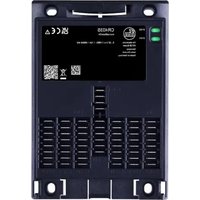
CR403S - Automaton IFM - Free user manual and instructions
Find the device manual for free CR403S IFM in PDF.


User questions about CR403S IFM
0 question about this device. Answer the ones you know or ask your own.
Ask a new question about this device
Download the instructions for your Automaton in PDF format for free! Find your manual CR403S - IFM and take your electronic device back in hand. On this page are published all the documents necessary for the use of your device. CR403S by IFM.
USER MANUAL CR403S IFM
Operating instructions
ecomat
Basic
CR403S
HW version: V2.0.3.x
Contents
1 Preliminary note.... 3
1.1 Manufacturer's address.... 3
1.2 Symbols used.... 3
1.3 Warnings.... 3
1.4 Safety symbol on the device 4
2 Safety instructions 5
3 Transport, handling and storage 6
4 Intended use 7
4.1 Predictive incorrect use.... 7
5 Items supplied 8
5.1 Accessories 8
6 Installation....9
6.1 Installation location.... 9
6.2 Mounting surface 9
6.3 Heat dissipation.... 9
6.4 Fastening 9
7 Electrical connection 11
7.1 Male spade connectors 6.3 x 0.8 mm.... 11
7.2 Wiring.... 12
7.3 Fuses 14
7.4 Laying of the supply and signal cables.... 15
7.4.1 GND connections.... 16
7.5 Analogue inputs 17
7.6 Resistor inputs 17
7.7 High-side digital inputs (CSO) 18
7.8 Digital / PWM outputs 18
7.9 Mixed operation (12 V / 24 V).... 19
7.10 For the scope of validity UL 19
8 Set-up 21
8.1 Interfaces and system requirements 21
8.2 Required documentation 21
9 Maintenance, repair and disposal 22
1 Preliminary note
You will find instructions, technical data, approvals and further information using the QR code on the unit / packaging or at documentation.ifm.com.
1.1 Manufacturer's address
ifm electronic gmbh
Friedrichstraße 1
45128 Essen
Germany
www.ifm.com
info@ifm.com
1.2 Symbols used
√ Requirement
Instruction
Reaction, result
bold Designation of keys, buttons or indications
→ Cross-reference without link
→ Cross-reference with link
Important note Non-compliance may result in malfunction or interference
Information Supplementary note
1.3 Warnings
Warnings indicate the possibility of personal injury and damage to property. This enables safe product handling. Warnings are graded as follows:

WARNING
Warning of serious personal injury
▷ If the warning is not observed, fatal and serious injuries are possible.

CAUTION
Warning of minor to moderate personal injury
▷ If the warning is not observed, minor to moderate injuries are possible.

ATTENTION
Warning of damage to property
▷ If the warning is not observed, damage to property is possible.
1.4 Safety symbol on the device

Safety symbol on the device:
▶ Adhere to the operating instructions for the safe operation of the unit.
2 Safety instructions
- The unit described is a subcomponent for integration into a system.
- ▶ The system architect is responsible for the safety of the system.
-
The system architect undertakes to perform a risk assessment and to create documentation in accordance with legal and normative requirements to be provided to the operator and user of the system. This documentation must contain all necessary information and safety instructions for the operator, the user and, if applicable, for any service personnel authorised by the architect of the system.
-
Read this document before setting up the product and keep it during the entire service life.
- The product must be suitable for the corresponding applications and environmental conditions without any restrictions.
- Only use the product for its intended purpose (→ Intended use).
- If the operating instructions or the technical data are not adhered to, personal injury and/or damage to property may occur.
- The manufacturer assumes no liability or warranty for any consequences caused by tampering with the product or incorrect use by the operator.
- Installation, electrical connection, set-up, programming, configuration, operation and maintenance of the product must be carried out by personnel qualified and authorised for the respective activity.
- Protect units and cables against damage.
- Replace damaged units, otherwise the technical data and safety will be impaired.
- Observe applicable documents.

ATTENTION
Excessive current, weld slag and soiling due to welding
▷ Damage to the device, deterioration of the electrical safety
▶ Welding work on the chassis frame must only be carried out by qualified personnel.
▶ Remove and cover the plus and minus terminals of the batteries.
▶ Disconnect all contacts of the device from the on-board system prior to welding on the vehicle or machine.
▶ Connect the earth terminal of the welding device directly to the part to be welded.
▶ Do not touch the device or electric cables with the welding electrode or the earth terminal of the welding device.
▶ Protect the device incl. all connectors and all connection cables against weld slag and soiling.
3 Transport, handling and storage
▶ Store the device in its original packaging.
▶ When the device is to be stored again, use the original packaging.
▶ Otherwise, provide unused connections with either a mating connector or a protective cap and pack the device in suitable packaging.
▶ Observe the permissible ambient conditions for the device during storage (→ Technical data).
4 Intended use
The freely programmable controllers of the “ecomat
Basic” series are rated for use under difficult conditions: this includes an extended temperature range, strong vibration, intensive EMC interference.
Permitted use:
- in mobile machines with supply from on-board systems (with battery) of 12 V DC or 24 V DC nominal voltage
- in an industrial environment as a permanently installed device with supply from SELV/PELV according to the technical data

This is a class A product. This product may cause radio interference in domestic areas.
▶ If required, take appropriate EMC screening measures.
- Two separately programmable PLCs:
- CODESYS V3.5 programming system (in a version approved by ifm) for both controllers.
- Only use the device within the limits of the technical data: ➞ Technical data.
- Mounting location: ➞ Installation location

By default, the device is not intended for direct connection to IT systems. If this application is required, the user has to implement it (e.g. by using their own additional components).
Please observe the following document: “Operating instructions (supplement) - Cyber Security” via documentation.ifm.com
Number of inputs: 12
Number of outputs: 12
Number of output groups: 2 (supplied via VBB 0...1 )
4.1 Predictive incorrect use
• Continuous operation 24/7 is not permitted.
• No use in safe applications.
• No installation on the motor/engine.
• No use in an environment with ionising radiation.
5 Items supplied
CR403S:
- 1 ecomat
Basic
• 4 tubular rivets with 4 washers
• CE declaration of conformity
• UK declaration of conformity
▶ In the event of incomplete or damaged items supplied, please contact ifm.

Documentation and software (device firmware and programming environment) at documentation.ifm.com and in the software package.
▶ Check online for the latest version.
5.1 Accessories

Information about available accessories at www.ifm.com
6 Installation
6.1 Installation location

The system architect is responsible for the stability of the mounting surface and fastening at the installation location. The weight of the device, environmental conditions of the application and local regulations must be taken into account.
The following installation locations are permitted for mobile use:
- Inside of the cabin
- Body
- Vehicle frame
Installation on the motor/engine is not permitted.
The applicable regulations must be complied with, taking into account the specified environmental conditions.
Environmental conditions: ➕ Technical data
▶ Take the protection rating and pollution degree into account.
The system architect is responsible for protecting the device in the application if the required protection rating or pollution degree for the device is not met.
6.2 Mounting surface

The housing must not be exposed to any torsional forces or mechanical stress.
▶ Use suitable compensating elements if there is no flat mounting surface available.

Fig. 1: Mounting surface
▶ During installation and storage, ensure that the pollution degree is 2 or better (IEC 60664-1).
6.3 Heat dissipation
The housing can heat up considerably.
▶ During installation, ensure sufficient heat dissipation at the installation location.
▶ Observe the maximum ambient temperature.
▶ Observe the parameters and specifications for temperature, altitude above sea level and frequency of the outputs specified in the technical data.
6.4 Fastening
▶ Insert the enclosed tubular rivets from the back of the device in the 4 fixing holes.
▶ Fix the device using 4 washers and M4 cylinder head bolts.
Tightening torque: 1.5 ± 0.2 Nm
Tighten the bolts alternately crosswise.

Fig. 2: Dimensions for the drill holes

Fig. 3: Insertion of the tubular rivets
1: Tubular rivets
2: Washers
3: Screws (not included)
7 Electrical connection

▶ Disconnect the machine from the mains supply before installation; if necessary, also disconnect any independently supplied input / output load circuits.
▶ Observe the national and international regulations for the installation of electrical equipment.
▶ Observe the requirements according to EN 60204.
The circuit is insulated from device surfaces that could be touched with basic insulation according to IEC 61010-1 (secondary circuit with max. 32 V DC, supplied from the mains circuit up to 300 V of overvoltage category II).
The basic insulation does not apply to connection areas (IP20).
The external wiring has to be carried out in a way that ensures the required separation from other circuits.

Observe all notes on connection technology.

Only connect the connector when the supply voltage is disconnected.
"Hot plugging" is not permitted.

The cable cross-sections must be matched to the operating currents/fuse rates.
▶ Note the device label.
▶ Provide unused connections with unpopulated contact housings.
▶ Provide all outgoing cables with suitable strain relief after a maximum of 200 mm. Observe the minimum bending radius of the cables ( ⇒ information from the cable manufacturer).
7.1 Male spade connectors 6.3 x 0.8 mm

The 6.3 x 0.8 mm male spade connectors are tin-plated. Functioning and technical data are guaranteed for up to 10 mating cycles.
Self-assembled cables:
- Contact housings must comply with a flammability classification of at least V-2 (V-0, V-1, V-2) according to IEC 60695.
• Insulated cables must be flame-retardant (VW-1 according to ANSI/UL 2556 or equivalent). - The maximum temperature for contact housings of ifm accessories is 105 °C. The system architect must guarantee this temperature in the application.
The temperature reached depends on the cable cross-section and the maximum currents.
When using cables with a cross-section of 1.5 mm2 , the technical data of the contact housing is ensured and the technical data of the device remains valid. - Observe the maximum number of mating cycles of the connectors.
7.2 Wiring

Fig. 4: Connectors
Assignment of the terminal blocks:
All VBB30 connections of the terminal blocks are connected to each other in the device.
Designation of the inputs and outputs:


Terminal blocks C1.0, C1.1
| Terminal block | Connection | Function |
| C1.0 | VBB30 | Controller supply |
| VBB0 | Output group 0 supply | |
| VBB1 | Output group 1 supply | |
| GND0 | Controller GND | |
| CAN0_H | CAN interface 0 (high) | |
| CAN0_L | CAN interface 0 (low) | |
| C1.1 | VBB30 | Controller supply |
| GND1 | Controller GND | |
| CAN1_H | CAN interface 1 (high) | |
| CAN1_L | CAN interface 1 (low) | |
| C2.0 | VBB30 | Sensor supply (fed from VBB30 of C1.0 / C1.1) |
| IN0400 | Frequency input (IN FREQUENCY-B) | |
| IN0401 | Frequency input (IN FREQUENCY-B) | |
| GND | Sensor GND | |
| GND | Sensor GND | |
| IN0500 | Frequency input (IN FREQUENCY-B) | |
| IN0501 | Frequency input (IN FREQUENCY-B) | |
| VBB30 | Sensor supply (fed from VBB30 of C1.0 / C1.1) | |
| C2.1 | VBB30 | Sensor supply (fed from VBB30 of C1.0 / C1.1) |
| IN0200 | Resistor input (IN RESISTOR-A) | |
| IN0201 | Resistor input (IN RESISTOR-A) | |
| GND | Sensor GND | |
| GND | Sensor GND | |
| IN0300 | Resistor input (IN RESISTOR-A) | |
| IN0301 | Resistor input (IN RESISTOR-A) | |
| VBB30 | Sensor supply (fed from VBB30 of C1.0 / C1.1) | |
| C2.2 | VBB30 | Sensor supply (fed from VBB30 of C1.0 / C1.1) |
| IN0000 | Multi-function input (IN MULTIFUNCTION-A) | |
| IN0001 | Multi-function input (IN MULTIFUNCTION-A) | |
| GND | Sensor GND | |
| GND | Sensor GND | |
| IN0100 | Multi-function input (IN MULTIFUNCTION-A) | |
| IN0101 | Multi-function input (IN MULTIFUNCTION-A) | |
| VBB30 | Sensor supply (fed from VBB30 of C1.0 / C1.1) |
Tab. 1: Terminal blocks C2.0, C2.1, C2.2
| Terminal block | Connection | Function |
| C3.0 | OUT0000 | Digital / PWM / PWM-I output 2.5 A (OUT PWM-25-A) |
| GND | Actuator GND | |
| OUT0001 | Digital / PWM / PWM-I output 2.5 A (OUT PWM-25-A) | |
| GND | Actuator GND | |
| OUT0002 | Digital / PWM output 2.5 A (OUT PWM-25-B) | |
| GND | Actuator GND | |
| OUT0003 | Digital / PWM output 2.5 A (OUT PWM-25-B) | |
| GND | Actuator GND | |
| C3.1 | OUT0004 | Digital / PWM output 1 A (OUT PWM-10-D) |
| GND | Actuator GND | |
| OUT0005 | Digital / PWM output 1 A (OUT PWM-10-D) | |
| GND | Actuator GND | |
| OUT0006 | Digital / PWM output 1 A (OUT PWM-10-D) | |
| GND | Actuator GND | |
| OUT0007 | Digital / PWM output 1 A (OUT PWM-10-D) | |
| GND | Actuator GND | |
| C3.2 | OUT0100 | Digital / PWM output 2.5 A (OUT PWM-25-B) |
| GND | Actuator GND | |
| OUT0101 | Digital / PWM output 2.5 A (OUT PWM-25-B) | |
| GND | Actuator GND | |
| OUT0102 | Digital / PWM output 4.0 A (OUT PWM-40-B) | |
| GND | Actuator GND | |
| OUT0103 | Digital / PWM output 4.0 A (OUT PWM-40-B) | |
| GND | Actuator GND |
Tab. 2: Terminal blocks C3.0, C3.1, C3.2

The connection terminals may only be supplied with the signals specified in the technical data.

ATTENTION
Absence of reverse polarity protection for VBB0...1
▷ Reverse polarity protection is only ensured in case of supply via the on-board system (via a battery), if the polarity of the supply is reversed as a whole (battery connected incorrectly). The basic principle of the reverse polarity protection is that the upstream fuses are quickly switched off in case of excessive current caused by reverse polarity.
▷ In case of supply via SELV/PELV, reverse polarity protection is not ensured.
▷ Damage to the device
▶ Ensure proper connection to the connector before connecting the latter to the device, also in case of supply via the on-board system.

The device is designed for supply via a mobile on-board system (12/24 V DC nominal voltage) or SELV/PELV according to the technical data and national regulations. The supply is directly transferred to the connected sensors/actuators without electrical separation.

WARNING
Risk of confusing C2.0, C2.1 and C2.2 connectors
Risk of confusing C3.0, C3.1 and C3.2 connectors
▷ Loss of fire protection
▷ Malfunctions
▷ Loss of the system functionality, damage to the system possible
▶ Ensure correct wiring and correct functioning.
7.3 Fuses

CAUTION
The input currents of the operating voltages are not limited.
▷ No fire protection without external fuses.
▶ Protect circuits.
▶ The individual electric circuits must be protected in order to protect the whole system.
Automotive blade-type fuses are recommended.
| Connection | Nominal value fuse | Required triggering characteristics |
| VBB30 | 2 A | Tfuse ≤ 120 s at max. 6.25 A |
| VBB0 | ≤ 15 A | - |
| VBB1 | ≤ 15 A | - |
| Supply sensors (with direct connection to supply) | ≤ 2 A | Tfuse ≤ 120 s at max. 6.25 A |

Protection against load dump:
▶ Load dump protection for the VBB1 connection is integrated into the device.
▶ VBB1 must be connected for protection against load dump.
▶ For protection against load dump, use a 15 A fuse and cable with a cross-section of 1.5 mm 4 .
▶ Load dump protection for VBB30 is only available when VBB1 and VBB30 are connected to the same potential.
7.4 Laying of the supply and signal cables

Fig. 5: Connection of the supply and signal cables (X = not permitted)
1: GND star point
2: Load return to the common star point
3: Load return via the associated GND pin of terminal blocks C3.n
4: Supply of the sensors via the VBB 30 and GND contacts of terminal blocks C2.n
5: Supply of the sensors via fuse: Fuses → 14

Bridging of connections in the connectors is not permitted.

Faulty laying of the supply and signal cables
▷ Deterioration of EMC may occur
▶ Lay supply and signal cables separately, take EMC / application into account
▶ Connect supply and ground cables to the controller and to the sensors / actuators via the respective common star point or via the corresponding terminal blocks C2.x / C3.x.

If a prewired connection cable is used, remove unused cores.
In case of signal failures, operate inputs with shielded cables. Connect the shields to the shield / functional earth connection on one side.

WARNING
Overvoltage > 36 V (unprotected)
▷ Risk of personal injuries and/or damage to property.
▷ Uncontrollable and unpredictable dangerous behaviour of the controller, e.g. all outputs activated.
▶ Provide external protection against overvoltage.
The CAN bus is internally protected against short circuit to VBB and GND.

For CAN cables ≥ 30 m, ensure appropriate protection (e. g. shielded cables).
VBB30 is protected against reverse polarity.
▶ Connect all required supply lines (VBB 30 , VBB 0 , VBB 1 ). VBB 30 can be connected to C1.0 or C1.1.
7.4.1 GND connections

CAUTION
Incorrect GND connection
- Not all GND connections of the controller (GND 0...1 ) are connected to the star point ①
- Different cable cross-sections
- Different cable lengths
▷ Risk of fire
▷ Inadmissible heating
▶ Connect all GND connections of the controller ( GND0...1 ) to the GND star point ①.
▶ Use the same cable cross-section for all GND connections of the controller.
▶ Use the same cable length for all GND connections of the controller.
▶ Connect the controller connections (GND 0...1 ) individually to the common GND star point ①.
▶ Connect the GND connections of the sensors to the GND connections of the corresponding terminal block.
▶ Connect the GND connections of the actuators (loads) to the common GND star point or to the GND connections of the corresponding terminal block.
All GND connections are connected to each other in the device.
7.5 Analogue inputs

Fig. 6: Connection of the analogue inputs (X= not permitted)
1: GND star point
2: Fuse for the supply of the sensors: Fuses ➕ 14
▶ Connect the GND of the signal source to the corresponding GND connection of terminal block C2.n. Do not connect the GND of the signal source to the common GND star point ①.
7.6 Resistor inputs

Fig. 7: Connection of the resistor inputs (X= not permitted)
1: GND star point
▶ Connect the GND of the signal source to the corresponding GND connection of terminal block C2.n. Do not connect the GND of the signal source to the common GND star point ①.
▶ Do not connect the resistor inputs to a VBB.
7.7 High-side digital inputs (CSO)

Fig. 8: Connection of the high-side inputs (X= not permitted)
1: GND star point
2: Fuse for the supply of the sensors: Fuses ➕ 14
▶ Connect the GND of the signal source to the corresponding GND connection of terminal block C2 or the common GND star point.
7.8 Digital / PWM outputs

Fig. 9: Connection of the high-side digital outputs (X= not permitted)
1: GND star point

WARNING
Disconnection of the GND star point while loads connected to the outputs are still connected to GND of the supply (see figure above, dashed line)
This may cause fault currents to flow through the controller and load which lead to an undefined state of the controller and the system.
▷ Loss of correct function
▶ Always connect the ground cable of the controller and the loads (actuators) via the common GND star point ① (see image above).
▷ This ensures that the loads are no longer connected to GND if the line to the supply is interrupted.
The controller can be connected to the following loads:
- resistive loads
- capacitive loads (adapt diagnostic settings to the load, see programming manual)
- inductive loads
The connected load must not exceed the maximum permissible values of the respective output ( → Technical data).

Deviating connections are not permitted.
7.9 Mixed operation (12 V / 24 V)

Mixed operation is not permissible when supplied by SELV/PELV. Mixed operation is only permissible when supplied by an on-board system.

Fig. 10: Example connection to 24 V and 12 V power supply combined
1: GND star point
2: Fuse for the supply of the sensors: Fuses → 14
7.10 For the scope of validity UL
This is an open type model that must be mounted in a suitable cabinet or enclosure.
Indoor use.
Use UL-certified cables of category CYJV 2/7/8 with mim 95 °C suitable ratings for connecting the device.
Cables must be protected against accidental removal (strain relief). 6.3 x 0.8 mm connectors must be certified under the RFWV/RFWV7.
The device may only be connected to Ethernet networks and CAN bus running indoors and without being exposed to TNV circuits.
8 Set-up
8.1 Interfaces and system requirements
The programmer creates the application program with the IEC 61131-3 compliant CODESYS programming system and loads the applications to the controller via the CAN interface. For the required information about installation and set-up, see the programming manual.
Required components:
- Suitable CODESYS version (→ Programming manual)
• CODESYS plug-ins
• CODESYS package for the controller - Firmware
- Release notes
To program the controller, the persons should be familiar with the CODESYS software.
Moreover, they should be familiar with the following topics:
• Required user-specific standards
8.2 Required documentation
In addition to the CODESYS programming system, the following documents are required for programming and set-up of the device:
- Programming manual for the firmware version used
- Operating instructions (supplement) - Cyber security

Documentation and software (device firmware and programming environment) at documentation.ifm.com and in the software package.
▶ Check online for the latest version.
CODESYS online help: contained in CODESYS installation (documentation.ifm.com).
9 Maintenance, repair and disposal
The unit is maintenance-free.
▶ Contact ifm in case of malfunction.
It is not possible to repair the device.
Delete all data before disposing of or returning the device:
▶ If necessary, create a data backup before deleting: Backup and restore
▶ Delete all passwords on the device, e.g. by resetting to factory settings (Factory Reset).
▶ Delete all programs and user data on the device, e.g. by resetting to factory settings (Factory Reset).
Disposal:
▶ After use, dispose of the unit in an environmentally friendly way in accordance with the applicable national regulations.
Cleaning the unit:
▶ Disconnect the unit from the voltage supply.
▶ Clean the unit from dirt using a soft, chemically untreated and dry micro-fibre cloth.
- 1 PRELIMINARY NOTE
- 1.1 MANUFACTURER'S ADDRESS
- 45128 ESSEN
- 1.2 SYMBOLS USED
- 1.3 WARNINGS
- 1.4 SAFETY SYMBOL ON THE DEVICE
- 2 SAFETY INSTRUCTIONS
- 3 TRANSPORT, HANDLING AND STORAGE
- 4 INTENDED USE
- 4.1 PREDICTIVE INCORRECT USE
- 5 ITEMS SUPPLIED
- 5.1 ACCESSORIES
- 6 INSTALLATION
- 6.1 INSTALLATION LOCATION
- 6.2 MOUNTING SURFACE
- 6.3 HEAT DISSIPATION
- 6.4 FASTENING
- 7 ELECTRICAL CONNECTION
- 7.1 MALE SPADE CONNECTORS 6.3 X 0.8 MM
- 7.2 WIRING
- 7.3 FUSES
- 7.4 LAYING OF THE SUPPLY AND SIGNAL CABLES
- 7.4.1 GND CONNECTIONS
- 7.5 ANALOGUE INPUTS
- 7.6 RESISTOR INPUTS
- 7.7 HIGH-SIDE DIGITAL INPUTS (CSO)
- 7.8 DIGITAL / PWM OUTPUTS
- 7.9 MIXED OPERATION (12 V / 24 V)
- 7.10 FOR THE SCOPE OF VALIDITY UL
- 8 SET-UP
- 8.1 INTERFACES AND SYSTEM REQUIREMENTS
- 8.2 REQUIRED DOCUMENTATION
- 9 MAINTENANCE, REPAIR AND DISPOSAL
Brand : IFM
Model : CR403S
Category : Automaton