
Marine M6008A - Receiver INFINITY - Free user manual and instructions
Find the device manual for free Marine M6008A INFINITY in PDF.

| Product Type | 8-Channel Marine Amplifier |
| Brand | Infinity |
| Model | Marine M6008A |
| Dimensions (L x H x D) | 360 mm x 56 mm x 180 mm |
| Weight | 3.8 kg |
| Operating Voltage | 9 ~ 16 VDC |
| Fuse Rating | 105 A |
| Amplifier Class | Class D |
| Output Power at 4 ohms (14.4 V) | 8 x 75 W RMS |
| Output Power at 4 ohms (12.8 V) | 8 x 65 W RMS |
| Output Power at 2 ohms (14.4 V) | 8 x 125 W RMS |
| Output Power at 2 ohms (12.8 V) | 8 x 100 W RMS |
| Output Power in Bridged Mode (14.4 V) | 4 x 250 W RMS |
| Output Power in Bridged Mode (12.8 V) | 4 x 200 W RMS |
| Frequency Response | 20 - 20,000 Hz |
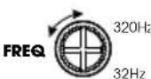
| Crossover Frequencies | 32 - 320 Hz variable, 12 dB/octave |
| Line Level Input Sensitivity | 200 mV RMS - 5 V RMS |
| High Level Input Sensitivity | 25 V RMS |
| Signal-to-Noise Ratio | 80 dB |
| THD+N at Rated Power | 1% |
| Recommended Wire Gauge (Power) | 4 AWG |
| Maintenance and Cleaning | Clean with a dry cloth. Avoid moisture. |
| Spare Parts and Repairability | For repair, refer to the warranty card. |
| Safety | Disconnect the negative battery terminal before installation. Wear safety goggles. |
Frequently Asked Questions - Marine M6008A INFINITY
User questions about Marine M6008A INFINITY
0 question about this device. Answer the ones you know or ask your own.
Ask a new question about this device
Download the instructions for your Receiver in PDF format for free! Find your manual Marine M6008A - INFINITY and take your electronic device back in hand. On this page are published all the documents necessary for the use of your device. Marine M6008A by INFINITY.
USER MANUAL Marine M6008A INFINITY
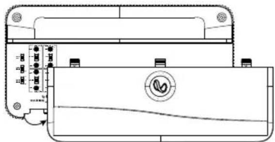
- Slide the panel cover down

- Remove panel cover
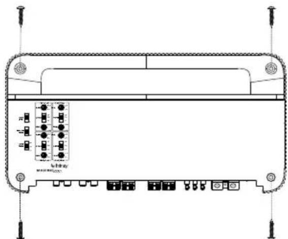
MOUNTING THE AMP
Note: It is recommended that you make all wire connections before mounting the amplifier.
IMPORTANT: Disconnect the negative (-) battery terminal of the accessory battery before beginning the installation.
Always wear protective eyewear when using tools.
- Choose a safe mounting location. Check clearances on both sides of a planned mounting surface. Be sure that screws or wires will not puncture the vessel hull, fuel lines, or wiring harnesses, and that wire routing will not interfere with the safe boat operation. Use caution when drilling or cutting in the mounting area.
- Choose a location that provides enough air circulation.
- Do not mount the amplifier with the heat sink facing downward, as this interferes with cooling.
- Mount the amplifier so that it will not be damaged by the feet of passengers or shifting cargo.
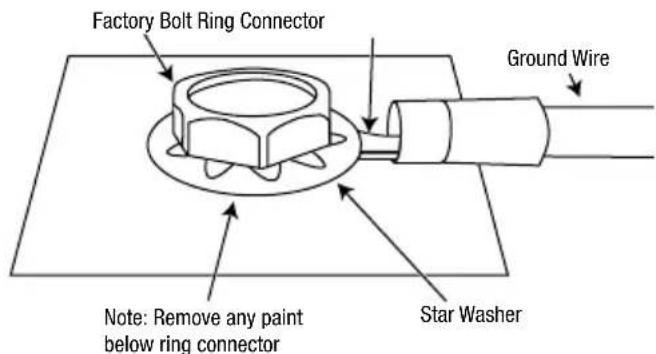
WIRING FOR POWER AND GROUND
At amplifier:

At ground location:
WIRING FOR INPUT SIGNAL
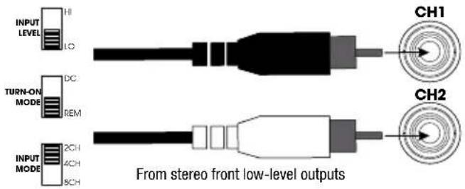
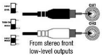
Low-level signals - 2-channel input
Note: when using 2-channel low-level signals and remote turn-on lead, set the INPUT LEVEL switch to LO, the TURN-ON MODE switch to REM, and the INPUT MODE switch to 2CH.
Low-level signals - 4-channel input
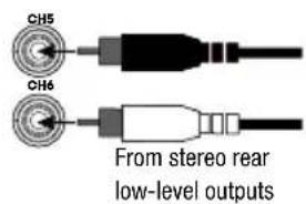
Note: when using 4-channel low-level signals and remote turn-on lead, set the INPUT LEVEL switch to LO, the TURN-ON MODE switch to REM, and the INPUT MODE switch to 4CH.
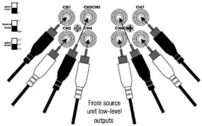
Low-level signals - 8-channel input
Note: when using 8-channel low-level signals and remote turn-on lead, set the INPUT LEVEL switch to LO, the TURN-ON MODE switch to REM, and the INPUT MODE switch to 8CH.
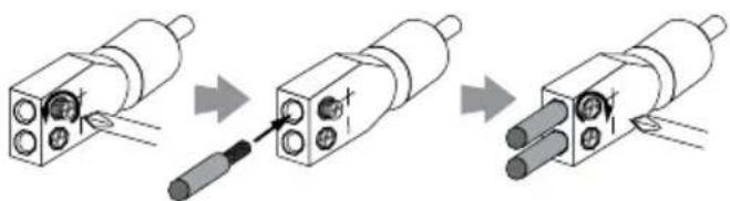
High-level input signals - Preparing adapters
Loosen Screws Insert Wires Tighten Screws
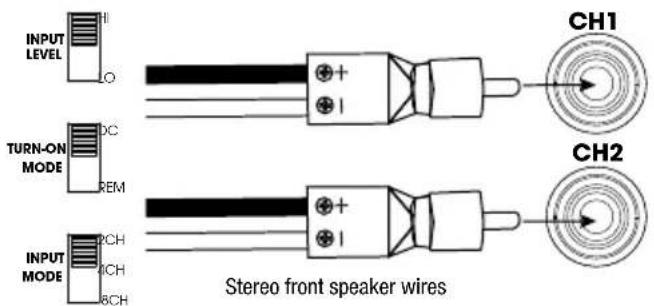
High-level input signals - 2-channel input
Note: when using 2-channel high-level signals, set the INPUT LEVEL switch to HI, the TURN-ON MODE switch to DC, and the INPUT MODE switch to 2CH.
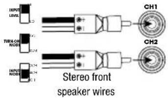
High-level input signals - 4-channel input
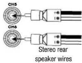
Note: when using 4-channel high-level signals, set the INPUT LEVEL switch to HI, the TURN-ON MODE switch to DC, and the INPUT MODE switch to 4CH.
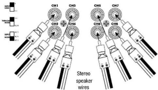
High-level input signals - 8-channel input
Note: when using 8-channel high-level signals, set the INPUT LEVEL switch to HI, the TURN-ON MODE switch to DC, and the INPUT MODE switch to 8CH.
WIRING FOR OUTPUT
Note: Be sure to observe proper speaker polarity.
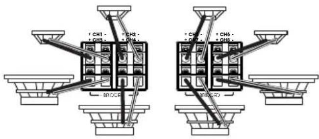
8-channel output
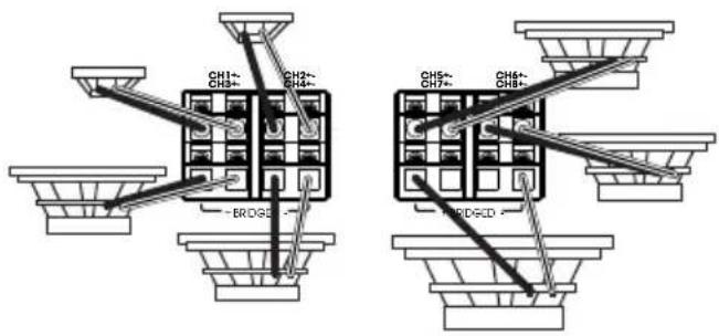
7-channel output
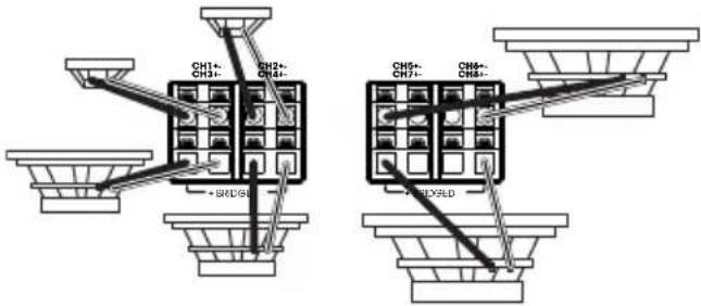
6-channel output
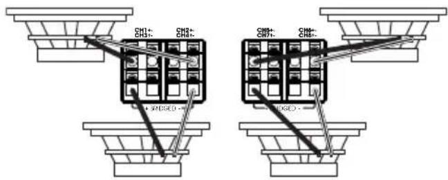
4-channel output
SETTING GAIN, CROSSOVERS, AND BASS BOOST
Setting the gain
1.Startwith GAIN control set to minimum, and the crossover control rotated midway.
2. For the front and rear channels, choose music you're familiar with. For the subwoofer channel on the Marine 6008A, choose music with substantial bass content.
3. Turn the volume control on your receiver to 14 of its total output.
4. Adjust the GAIN control clockwise, listening carefully to the bass output. If you hear distortion, turn the GAIN counterclockwise to decrease the gain.
Selecting the crossover mode
On the front and rear channels, you can select your preferred crossover mode.
Choose HPF to allow only frequencies above a certain point to reach your speakers. Recommended if you're using a subwoofer in your system, as it keeps low base from your full-range speakers.
Choose LPF to allow only frequencies below a certain point to reach your speakers. Recommended if you're bridging the front or rear channels to power a subwoofer.
Choose FULL to allow all frequencies to reach your speakers. Recommended if you're not using a subwoofer in your system.
Selecting the crossover frequency
Choose the crossover point to suit listening preferences. Turn the dials to the left to lower the crossover point and to the right to raise the crossover point. Exact crossover settings for coaxial speakers and subwoofer depend on your listening preferences.
Choose the crossover point to suit listening preferences. Turn the dials to the left to lower the crossover point and to the right to raise the crossover point. Exact crossover settings for coaxial speakers and subwoofer depend on your listening preferences.
SPECIFICATIONS
| Marine 6008A | |
| Power output @ 4 ohms (14.4V) | 75 watts RMS x 8 |
| Power output @ 4 ohms (12.8V) | 65 watts RMS x 8 |
| Power output @ 2 ohms (14.4V) | 125 watts RMS x 8 |
| Power output @ 2 ohms (12.8V) | 100 watts RMS x 8 |
| Marine 6008A | |
| Power output in bridged mode (14.4V) | 250 watts RMS x 4 |
| Power output in bridged mode (12.8V) | 200 watts RMS x 4 |
| Frequency response 20-20K Hz | |
| Crossover frequencies | 32-320 Hz variable, 12 dB/ octave |
| Line-level input sensitivity | 200mVrms - 5Vrms |
| High-level input sensitivity | 1Vrms - 25Vrms |
| Signal-to-noise ratio | 80 dB |
| THD+N @ rated power | 1% |
| Fuse rating | 105A |
| Operating voltage | 9 ~ 16VDC |
| Amplifier class | D |
| Dimensions (W x H x D) | 14-3/16" x 2-3/16" x 7-1/8" (360mm x 56mm x 180mm) |
| Weight | 3.8kg |
| Recommended wire gauge (Power) | 4 |
TROUBLESHOOTING
No audio and POWER INDICATOR is off.
- No voltage at BATT+ and/or REM terminals, or bad or no ground connection. Check voltages at amplifier terminals with VOM.
No audio and PROTECT INDICATOR flashes every 4 seconds.
DC voltage on amplifier output. Amplifier may need service; see enclosed warranty card for service information.
No audio and PROTECT and POWER INDICATORS flash.
Voltage less than 9V on BATT+ connection. Check boat charging system.
No audio and PROTECT INDICATOR is on.
- Amplifier is overheated. Make sure amplifier cooling is not blocked at mounting location. Or, there may be voltage greater than 16V (or less than 8.5V) on BATT+ connection. Check boat charging system.
Amplifier fuse keeps blowing.
- The wiring is connected incorrectly or there is a short circuit. Check wiring connections.
Distorted audio.
- Gain is not set properly. Check setting. Check wires for shorts or grounds. Amplifier or source unit may be defective.
Distorted audio and PROTECT INDICATOR flashes.
- Short circuit in speaker or wire. Remove speaker leads one at a time to locate shorted speaker or wire, and repair.
Music lacks dynamics or "punch".
- Speakers are not connected properly. Check speaker connections for proper polarity.
Engine noise—whining or clicking—in system when the engine is on.
- Amplifier is picking up alternator noise. First, check ground connection on the amplifier - a loose or improper ground is one of the main causes for noise. Turn down gain. Move RCA audio cables away from power wires. Installing an alternator noise filter on power line between battery and alternator might also be necessary.
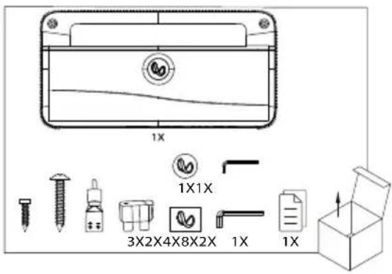
CONTENU DE LA BOITE
ACCÉS AUX CONNECTEURS / AU PANNEAU DE COMMANDE
- Gain is nichtJUST ingesteld. Controller instelling. Controller draden op kortsluiting of aarding. Versterker of bronnapparaat is möglichk defect.
Vervormd geluid en de BEVEILIGINGSINDICATOR knippert.
- IMPORTANT: Disconnect the negative (-) battery terminal of the accessory battery before beginning the installation.
- WIRING FOR POWER AND GROUND
- WIRING FOR INPUT SIGNAL
- WIRING FOR OUTPUT
- SETTING GAIN, CROSSOVERS, AND BASS BOOST
- Setting the gain
- Selecting the crossover mode
- Selecting the crossover frequency
- SPECIFICATIONS
- TROUBLESHOOTING
- No audio and POWER INDICATOR is off.
- No audio and PROTECT INDICATOR flashes every 4 seconds.
- No audio and PROTECT and POWER INDICATORS flash.
- No audio and PROTECT INDICATOR is on.
- Amplifier fuse keeps blowing.
- Distorted audio.
- Distorted audio and PROTECT INDICATOR flashes.
- Music lacks dynamics or "punch".
- Engine noise—whining or clicking—in system when the engine is on.
- CONTENU DE LA BOITE
- ACCÉS AUX CONNECTEURS / AU PANNEAU DE COMMANDE
- Vervormd geluid en de BEVEILIGINGSINDICATOR knippert.
Brand : INFINITY
Model : Marine M6008A
Category : Receiver