
Energysilence Aero 4200 invisible - Fan CECOTEC - Free user manual and instructions
Find the device manual for free Energysilence Aero 4200 invisible CECOTEC in PDF.

| Product type | Ceiling fan with integrated LED lighting |
| Brand | Cecotec |
| Model | Energysilence Aero 4200 Invisible |
| Available colors | WhiteWood, DarkWood, Black, White, Steel |
| Power supply | 220-240 V ~ 50/60 Hz |
| Motor power | 35 W (DC) |
| LED power | 36 W |
| LED energy efficiency class | E |
| Maximum airflow | 95.71 m³/min |
| Maximum air speed | 2.821 m/s |
| Sound power level | 44.793 dB(A) |
| Standby consumption | 0.43 W |
| Number of speeds | 6 |
| Timer | 1, 2, 4 and 8 hours |
| Summer/winter functions | Rotation direction reversal (summer: counterclockwise, winter: clockwise) |
| Lighting | LED lamp with color temperature adjustment (cool white to warm white) |
| Control type | Infrared remote control (AAA batteries 2×1.5 V) |
| Minimum distance from floor | 2.3 m |
| Minimum distance from walls/objects | 76 cm |
| Cleaning and maintenance | Soft lint-free cloth; do not use solvents or abrasive products |
| Warranty | Legal warranty; official Cecotec after-sales service at +34 9 63 21 07 28 |
Frequently Asked Questions - Energysilence Aero 4200 invisible CECOTEC
User questions about Energysilence Aero 4200 invisible CECOTEC
0 question about this device. Answer the ones you know or ask your own.
Ask a new question about this device
Download the instructions for your Fan in PDF format for free! Find your manual Energysilence Aero 4200 invisible - CECOTEC and take your electronic device back in hand. On this page are published all the documents necessary for the use of your device. Energysilence Aero 4200 invisible by CECOTEC.
USER MANUAL Energysilence Aero 4200 invisible CECOTEC
natural_image
Five modern pendant lights with different designs and colors, displayed against a dark background (no text or symbols visible)-
Parts and components
-
Before use
-
Product installation
-
Operation
-
Cleaning and maintenance 54
-
Troubleshooting
-
Technical specifications
B. Disposal of old electrical
and electronic appliances
-
Technical support and warranty
-
Copyright
57
SOMMAIRE
Read these instructions thoroughly before using the appliance. Keep this instruction manual for future reference or new users.
- This appliance can be used by children aged 8 years and above and people with reduced physical, sensory, or mental capabilities or lack of experience and knowledge if they have been given supervision or instruction concerning use of the appliance in a safe way and understand the hazards involved. Children must not play with the appliance. Cleaning and user maintenance should not be carried out by unsupervised children.
- Keep a minimum distance of 2.3 cm between the fan blades and the floor.
-
Keep a minimum distance of 76 cm between the fan blades and the wall or any other object.
-
Make sure the appliance is unplugged from the power supply before cleaning or user maintenance.
- This device is designed for domestic use only and is not intended for bars, restaurants, farmhouses, hotels, motels, and offices.
- Make sure that the mains voltage matches the voltage stated on the appliance marking and that the wall outlet is earthed.
- If the power cord is damaged, it must be replaced by the official Cecotec Technical Support Service to avoid any type of danger.
- Do not use the appliance if its cord or housing are damaged, nor after it malfunctions or has been dropped or damaged in any way.
- The appliance must be installed in accordance with national wiring regulations.
- Never insert objects or body parts between the rotating fan blades.
- To reduce the risk of injury, attach the fan directly to the support structure of the building as indicated in this manual and use only parts and components provided and recommended by Cecotec.
- Cut off the power completely before installing or repairing the fan to avoid the risk of electric shock.
- The electrical wiring must be in accordance with the local regulations.
- The cable must be properly earthed to avoid possible accidents.
- The appliance must be installed in accordance with national wiring regulations.
- Never install the fan in a damp or wet room.
-
Be careful when near the rotating fan blades.
-
To adjust the speed of the fan blades, only use the means for speed control provided by Cecotec.
- Do not bend the blade-attachment system during the installation or cleaning process.
- Cleaning and maintenance must be carried out according to this instruction manual to make sure the appliance works properly. Turn off and unplug the appliance before cleaning it.
- Make sure the fan is not placed close to curtains or other objects it may become entangled with.
- In order to ensure your children's safety, please keep all packaging (plastic bags, boxes, polystyrene, etc.) out of their reach.
- It is recommended that two people install the appliance.
- This appliance is designed for indoor use.
Instructions on batteries
- Battery ingestion can cause burns, soft-tissue perforation, and death. It can cause severe burns within two hours of the ingestion.
- In case of battery ingestion, please seek medical attention immediately.
- Do not allow children to replace batteries without adult supervision.
- Do not disassemble, open, or damage the batteries.
- Keep the batteries out of the reach of children. Pay particular attention to small batteries. In case of battery ingestion, please seek medical attention immediately.
- Do not expose batteries to heat or fire. Avoid storage in direct sunlight.
- Do not short-circuit an element or a battery. Do not store batteries in an untidy manner, in a box, or drawer where they
can short-circuit each other or be short-circuited by other metal objects.
- Both batteries and cells can leak under extreme conditions. In the event of a battery leak, keep your skin and eyes away from the liquid. If the liquid gets into contact with skin, wash immediately with soap and water. If the liquid gets into the eyes, wash them immediately with clean water for a minimum of 10 minutes and seek medical attention. Wear gloves to handle the battery and dispose of it immediately in accordance with local regulations.
- Pay attention to the positive (+) and negative (-) marks on the batteries and the remote-control compartment to ensure they are inserted correctly.
- Do not use any batteries that are not designed for use with the appliance.
- Do not mix batteries of different manufacture, capacity, or size. Children should be allowed to handle the batteries only under adult supervision.
- Always buy recommended batteries.
- Keep the batteries clean and dry. Wipe the battery terminals with a clean, dry cloth if they become dirty.
- Keep the original instruction manual for future reference.
- Whenever possible, remove the batteries when not in use.
INSTRUCTIONS DE SÉCURITÉ
| No. Description | Quantity | |
| 1 Mounting bracket 1 | ||
| 2 Hanging ball 1 | ||
| 3 Downrod 1 | ||
| 4 Canopy 1 | ||
| 5 Canopy screws 2 | ||
| 6 Pin 1 | ||
| 7 Clevis pin 1 | ||
| 8 | Downrod cover 1 | |
| 9 | Motor assembly | 1 |
| 10 | Lampshade | 1 |
| 11 | Remote control | 1 |
| 12 Receiver | 2 | |
NOTE:
The graphics in this manual are schematic representations and may not exactly match the device.
2. BEFORE USE
This appliance is packaged in a way as to protect it during transport. Take the appliance out of its box and remove all packaging materials. You can keep the original box and other packaging elements in a safe place. This will help you prevent damage to the appliance when transporting it in the future. In case the original packaging is disposed of, make sure all packaging materials are recycled accordingly.
- Make sure all parts and components are included and in good conditions. If there is any piece missing or in bad conditions, contact the official Cecotec Technical Support Service immediately.
ENGLISHENGLISH
Box content
- Far
- Assembly kit
LED light - Remote control
- AAA batteries
- Instruction manual
3. PRODUCT INSTALLATION
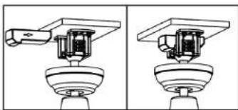
- Securely fasten the mounting bracket to the junction box (Fig. 2a) or ceiling joist (Fig. 2b) using the self-tapping screws, plain washers and pressure washers provided.
Fig. 2a key
- Wooden joist
- Junction box
- Rubber seal
- Mounting bracket
- Plain washer
- Junction box screws
- Pressure washer
- Ceiling
Fig. 2b key:
- Ceiling joist
- Mounting bracket
-
Self-tapping screws/plain washer/pressure washer
-
Loosen the hanging ball screws until the ball slides down the downrod. Remove the downrod pin (Fig. 3). Reinstall the hanging ball after step 4.
Fig. 3 key
- Hanging ball
- Pin
-
Screws
-
Remove the pin and the clevis pin from the downrod. Slide the downrod through the canopy and the coupling cover. Fig. 4
Fig. 4 key
- Canopy
- Pin
- Downrod cover
-
Clevis pin
-
Remove the two screws from the downrod. Then, place the downrod in the downrod cover. Fig. 5
Fig. 5 key
- Downrod
- Cover
- Pin
- Clevis pin
-
Screws
-
Pass the fan wires and the earth wire through the downrod.
- Insert the pin through the downrod holes and the cover. Make sure that the straight part of the clevis pin is properly inserted into the hole at the end of the pin, so that the curved part fits correctly into this part.
- Finally, retighten the screws.
Warning: It is very important that the clevis pin is correctly positioned into the cover and that the screws are properly tightened. If the pin, clevis pin or screws are not correctly positioned, the fan may fall down.
- Lift the fan carefully and place the downrod and hanging ball in the mounting bracket attached to the ceiling or junction box. Make sure that the groove in the hanging ball is properly aligned with the tab on the mounting bracket. Fig. 6.
Fig. 6 key
- Mounting bracket
- Tab
- Groove
Warning: the fan must be placed at a minimum distance of 230 cm from the floor.
- Place the lampshade on the light plate (built-in 36 W LED) by turning it clockwise. Make sure it is secure, but do not over-tighten. Fig. 7
ENGLISHENGLISH
Fig. 7 key
-
Light plate
-
Lampshade
Connections
Warning: to avoid the risk of electric shock, be sure to disconnect the main power supply to the electrical panel before connecting the cables.
- Connect the 120 V - 60 Hz main power (house) to the fan located on the mounting bracket as shown below.
- Insert the receiver into the mounting bracket with the flat side facing the ceiling. Fig. 8
Earth wire connections
- Connect the green/yellow wire from the mounting bracket and downrod to the earth wire of the power supply using a wire nut.
Electrical connections from the motor to the receiver
- Connect the white wire of the fan to the white output cable of the receiver via its male/female connector.
- Connect the blue wire of the fan to the blue output cable of the receiver via its male/female connector.
- Connect the 3-wire terminals of the fan to the 3-wire terminals of the receiver by means of the male/female connector.
Electrical connections from the receiver to the main power supply. Fig. 9
- Connect the white wire from the receiver to the neutral wire of the power supply using a wire nut.
- Connect the black wire from the receiver to the line wire of the power supply using a wire nut.
Fig. 9 key
- Power supply circuit
- Live wire
- Black (L)
- 3-wire terminal
- 3-wire terminal
- Neutral
- Earth wire
- White (N)
- Remote control
-
White
-
Blue
- Blue
- White
-
Earth wire
-
Attach the canopy to the mounting bracket using the screws as shown in Figure 10.
Fig. 10 key
- Canopy
- Canopy screws
4. OPERATION
This fan is operated by a remote control.
- Restore power to the junction box from the house's electrical panel
- Remove the battery-compartment cover of the remote control, insert the batteries, and replace the cover.
Note:
- The remote control is powered by two AAA 1.5 V batteries.
If the fan is not to be used for a long period of time, store the remote control in a dry place where it will not be exposed to heat or direct sunlight. Also remove the batteries.
- The remote control buttons control the speed and light of the fan.
Remote control
Fig. 11
- Power indicator light
- Speed setting
- Fan OFF button
- Blade reversal button
- Natural Breeze button
- Light on/off button/Shade change button
-
Timer buttons
-
The indicator will light up while the appliance is in operation.
- Use the speed buttons to select the power level. The fan has 6 speeds, 1 is the lowest and 6 is the most powerful.
- Press the off button to switch off the fan.
ENGLISHENGLISH
- Use the timer buttons to select the operation time of the appliance. The fan will turn off once the selected time has elapsed. The timer has 1, 2, 4 and 8 hour settings.
- Press the light button to turn the fan's light on and off. You can also change the shade of the light.
Winter/Summer function
- Use the blade reversal button to activate the reverse rotation.
- Winter function: the blades start to rotate clockwise, causing warm air to be distributed throughout the room.
- Summer function: the blades start to rotate counterclockwise, generating a cool breeze.
Pairing between remote control and receiver
As soon as the receiver is switched on, press, and hold the button on the remote control for two seconds. After this time, you will hear a beep, signifying successful pairing.
Note: the remote control has been paired with the receiver at the factory, so it can be used directly after installation of the fan. However, if you change the remote control or if you use another remote control, you will have to follow the previous step.
Note
- If the remote control cannot control the receiver, check if the batteries make contact, if they are inserted correctly and if they are not flat.
- If the remote control cannot control the receiver, check if there are other appliances operating with a remote control nearby, as they may cause interference. If you remove these appliances from the room where the fan is located, the remote control will work properly again.
- Use this appliance with the correct voltage. If the voltage is too low, the remote control will not work.
- If you are not going to use the remote control for a long period of time, remove the batteries.
5. CLEANING AND MAINTENANCE
- Clean the fan regularly
- When cleaning, only use a soft brush or lint-free cloth to avoid scratching the finish.
- Do not use abrasive cleaning agents as they could damage the appliance.
Warning: do not use solvents to clean the fan. Doing so could damage the motor and may result in a risk of electric shock.
RECOMMENDATION: periodically check that the blades are securely fastened to the motor with the screws.
54
ENERGYSILENCE AERO 4200 INVISIBLE WHITEWOOD/DARKWOOD
ENERGYSILENCE AERO 4200 INVISIBLE BLACK/WHITE
ENERGYSILENCE AERO 4200 INVISIBLE STEEL
6. TROUBLESHOOTING
Wobble
Note that not all ceiling fans are the same (not even those that are the same model), some move more than others. The fact that the fan moves a couple of centimetres does not indicate that it will fall over.
Even if all blades are ballasted and grouped by weight, it is impossible to completely avoid wobble. This is not a problem. Ceiling fans tend to move during operation.
To reduce wobble, try the following:
- Check that all of the blade mounting screws are tightened and secure.
- Fan wobble may be caused by the unevenness of the fan blades. To check the blade level, measure the distance from each blade tip to the ceiling.
If measurements are irregular:
- Be sure the blade mount screws are not too tight or too loose, which may cause wobbling due to an unlevelled blade tip.
- A deformed blade can cause wobbling. Check by removing the blade and placing on a flat surface.
- Blade tracking may be checked simply by use of a household ruler. Place the ruler vertically against the ceiling and even with the outside leading edge of a blade. Note the distance of the edge of a blade compared to the others. Turn the blade slowly by hand to check the remaining blades.
If a blade is not in alignment, the blade is either out of shape, warped or the blade screws are not evenly tightened or either loose.
7. TECHNICAL SPECIFICATIONS
Product reference: 00658 / 00659 / 00660 / 00661 / 00662
Product:
EnergySilence Aero 4200 Invisible WhiteWood
EnergySilence Aero 4200 Invisible DarkWood
EnergySilence Aero 4200 Invisible Black
EnergySilence Aero 4200 Invisible White
EnergySilence Aero 4200 Invisible Steel
Voltage: 220-240 V\~
Frequency: 50/60 Hz
Power: 35 W DC
Led: 36 W
ENERGYSILENCE AERO 4200 INVISIBLE WHITEWOOD/DARKWOOD
ENERGYSILENCE AERO 420D INVISIBLE BLACK/WHITE
ENERGYSILENCE AERO 4200 INVISIBLE STEEL
ENGLISHENGLISH
| Description Symbol Value Unit | |||
| Fan maximum flow F 95.71 m | 3/min | ||
| Fan power consumption P 30.55 W | |||
| Service value | SV | 3.13 | (m2/min)/W |
| Power consumption on standby mode | P_ss | 0.43 | W |
| Fan sound power level | L_w | 44.793 | dB (A) |
| Maximum air speed | C 2.821 m/seg | ||
| Service value measurement standard | IEC 60879:2019 | ||
| Contact details to obtain more information | Cecotec Innovaciones SL.Av. Reyes Catúlicos, No 60, 46910.Altafar (Valencia, Spain) | ||
The power consumption in standby mode is 0.43 W using the guidelines of EN 50564:2011 and the European regulations 1275/2008/EC and 801/2013/EC. For this purpose, the device is connected to the mains without performing any function, waiting for the standby mode to be activated.
This product features a light source with an energy efficiency grade E.
Technical specifications may change without prior notification to improve product quality. Made in China | Designed in Spain
8. DISPOSAL OF OLD ELECTRICAL AND ELECTRONIC APPLIANCES

This symbol indicates that, according to the applicable regulations, the product and/or batteries must be disposed of separately from household waste. When this product reaches the end of its shelf life, you should dispose of the cells/batteries/accumulators and take them to a collection point designated by the local authorities.
Consumers must contact their local authorities or retailer for information concerning the correct disposal of old appliances and/or their batteries.
Compliance with the above guidelines will help protecting the environment.
9. TECHNICAL SUPPORT AND WARRANTY
Cecotec shall be liable to the end user or consumer for any lack of conformity that exists at the time of delivery of the product under the terms, conditions, and deadlines established by the applicable regulations.
It is recommended that repairs be carried out by qualified personnel.
If at any moment you detect any problem with your product or have any doubt, do not hesitate to contact the official Cecotec Technical Support Service at -34 95 321 07 28.
10. COPYRIGHT
The intellectual property rights over the texts in this manual belong to CECOTEC INNOVACIONES, S.L. All rights reserved. The contents of this publication may not, in whole or in part, be reproduced, stored in a retrieval system, transmitted, or distributed by any means (electronic, mechanical, photocopying, recording or similar) without the prior authorization of CECOTEC INNOVACIONES, S.L.
FRANÇAISFRANÇAIS
1. PIÈCES ET COMPOSANTS
Image 1
3. INSTALLATION DU PRODUIT
Se as medidas forem irregulares:
6. PROBLEEMOPLOSSING
Wiebelen
-
Lamba plakasi
-
Tavan lambasi
TÜRKÇETÜRKÇE
Bağlantılar
Fig./Img./Abb./Afb./Rys./Obr.1

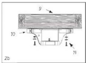
Fig./img./Abb./Afb./Rys./Obr.2
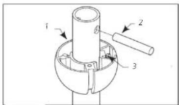
Fig./img./Abb./Afb./Rys./Obr.3
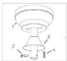
Fig./Img./Abb./Afb./Rys./Obr. 4
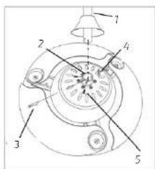
Fig./Img./Abb./Afb./Rys./Obr.5
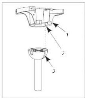
Fig./Img./Abb./Afb./Rys./Obr. 6
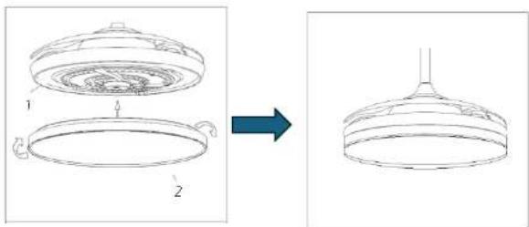
Fig./Img./Abb./Afb./Rys./Obr.7
natural_image
Technical line drawing of a mechanical assembly with two views (no text or symbols)Fig./Img./Abb./Afb./Rys./Obr. 8
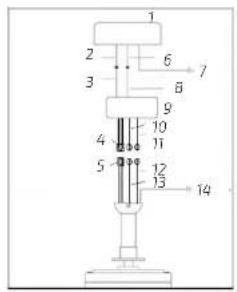
Fig./Img./Abb./Afb./Rys./Obr.9
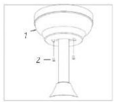
Fig./Img./Abb./Afb./Rys./Obr.10
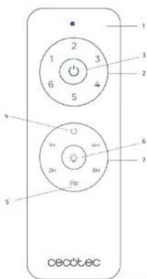
Fig./Img./Abb./Afb./Rys./Obr. 11
www.cecotec.es
- SOMMAIRE
- Instructions on batteries
- INSTRUCTIONS DE SÉCURITÉ
- BEFORE USE
- ENGLISHENGLISH
- Box content
- PRODUCT INSTALLATION
- Connections
- Earth wire connections
- Electrical connections from the motor to the receiver
- Electrical connections from the receiver to the main power supply. Fig. 9
- OPERATION
- Remote control
- Winter/Summer function
- Pairing between remote control and receiver
- Note
- CLEANING AND MAINTENANCE
- TROUBLESHOOTING
- Wobble
- TECHNICAL SPECIFICATIONS
- DISPOSAL OF OLD ELECTRICAL AND ELECTRONIC APPLIANCES
- TECHNICAL SUPPORT AND WARRANTY
- COPYRIGHT
- FRANÇAISFRANÇAIS
- PIÈCES ET COMPOSANTS
- INSTALLATION DU PRODUIT
- PROBLEEMOPLOSSING
- Wiebelen
- TÜRKÇETÜRKÇE
- Bağlantılar
Brand : CECOTEC
Model : Energysilence Aero 4200 invisible
Category : Fan