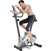
SP37363 - Indoor bike trainer COSTWAY - Free user manual and instructions
Find the device manual for free SP37363 COSTWAY in PDF.


| Product Type | Magnetic Exercise Bike |
| Brand | Costway |
| Model | SP37363 |
| Maximum User Weight | 110 kg |
| Resistance | 8 adjustable levels (1 to 8) |
| Resistance System | Magnetic |
| Electronic Monitor | LCD with display of time, speed, distance, odometer, calories, heart rate |
| Heart Rate Sensor | Ear clip and/or handlebar sensors |
| Monitor Power Supply | 2 AA or AAA 1.5V batteries (not included) |
| Backup Battery | Not specified |
| Display Type | LCD, backlight not specified |
| Monitor Functions | Auto scan, lock, reset |
| Dimensions (assembled) | Not provided, estimated 100x50x120 cm |
| Product Weight | Not provided, estimated 20-30 kg |
| Materials | Steel, plastic, foam |
| Handlebars | Padded, with sensor handles |
| Seat | Padded, height adjustable |
| Pedals | Standard pedals with cage (L/R) |
| Noise level | Quiet (belt drive) |
| Assembly required | Yes, tools provided (wrenches) |
| Maintenance | Gentle cleaning, check screws, no harsh chemicals |
| Safety | Read instructions before use, do not use by children without supervision |
| Spare Parts | Available via after-sales service (full list in manual) |
| Warranty | Not specified, refer to seller |
| Usage | Indoor, on flat surface |
Frequently Asked Questions - SP37363 COSTWAY
User questions about SP37363 COSTWAY
0 question about this device. Answer the ones you know or ask your own.
Ask a new question about this device
Download the instructions for your Indoor bike trainer in PDF format for free! Find your manual SP37363 - COSTWAY and take your electronic device back in hand. On this page are published all the documents necessary for the use of your device. SP37363 by COSTWAY.
USER MANUAL SP37363 COSTWAY
natural_image
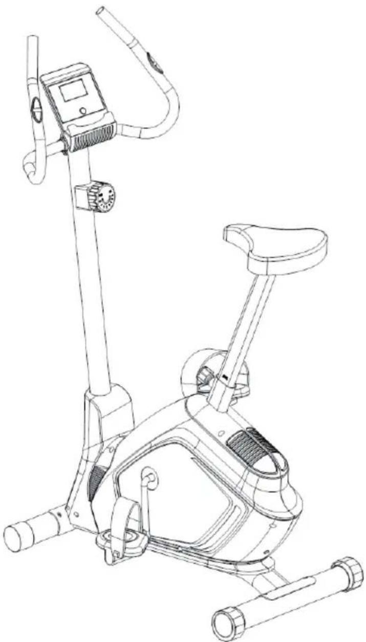
Line drawing of a stationary exercise bike with adjustable arms and legs (no text or symbols)USER'S MANUAL/HANDBUCH/MANUEL DE L'UTILISATEUR /MANUAL DEL USUARIO/MANUALE UTENTE/INSTRUKCJA OBSŁUGI
Magnetic Exercise Bike
SP37363
DEAR CUSTOMER,
PLEASE READ THIS INSTRUCTION VERY CAREFULLY BEFORE USING THE ITEM.
IMPORTANT SAFETY NOTICE:
Note the following precaution before assembling or operating the machine.
1、Assemble the machine exactly as the descriptions in the instruction manual.
2、Check all the screws, nuts and other connections before using the machine for the first time and ensure that the trainer is in the safe condition.
3、Set up the machine in a dry level place and leave it away from moisture and water.
4、Place a suitable base (e.g. rubber mat, wooden board etc.) beneath the machine in the area of assembly to avoid dirt and etc..
5、Before beginning training, remove all objects within a radius of 2 meters from the machine.
6、Do not use aggressive cleaning articles to clean the machine, Only use the supplied tools or suitable tools of your own to assemble the machine or repair any parts of machine. Remove drops of sweat from the machine immediately after finishing training.
7、Your health can be affected by incorrect or excessive training. Consult a doctor before beginning a training program. He can define the maximum setting (Pulse. Watts. Duration of training etc) to which you may train yourself and can get precise information during training. This machine is not suitable for therapeutic purpose.
8、Only do training on the machine when it is in normal working condition. Use only original spare parts for any necessary repairs.
9、This machine can be used for only one person's training at a time.
10、Wear training clothes and shoes, which are suitable for fitness training with the machine. Your training shoes should be appropriate for the trainer.
11、If you have a feeling of dizziness, sickness or other abnormal symptoms, please stop training and consult a doctor as soon as possible.
12、People such as children and handicapped persons should only use the machine in the presence of another person who can give aid and advice.
13、The power of the machine increases as the speed increases, and vice versa. The machine is equipped with adjustable knob, which can adjust the resistance. Reduce the resistance by turning the adjusting knob for the resistance setting towards stage 1. Increase the resistance by turning the adjusting knob for the resistance setting towards stage 8. The maximum user's weight is 110kgs
14、Care must be taken when lifting or moving the equipment so as not to injure your back.
Always use proper lifting techniques and/or use assistance.
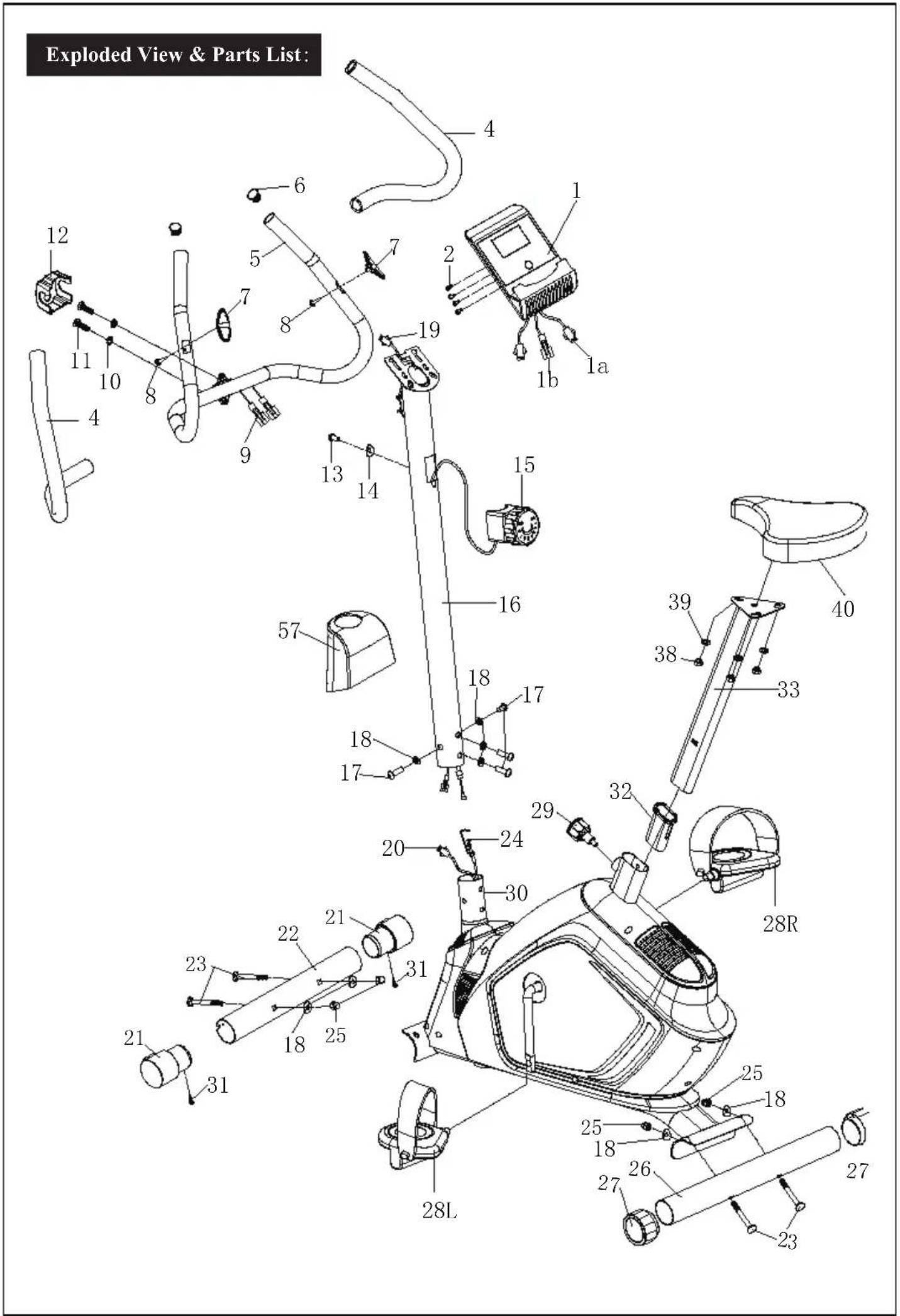

| NONAMEQUA.NONAMEQUA. | ||
| 1142Hexagon nut M62ter | ||
| 2Crossheadscrew M5*10443Axle1 | ||
| 3//44Snapringd122 | ||
| 4Foam 245Wash | ||
| 5 | Handlebar | 1 |
| 6End cap Φ25 | 2 | |
| 7 | Pulse sensor Φ25248Pinch roller | |
| 8 | Crosshead screw ST4.2*19 | 2 |
| 9250Magnet sensor wire | 4 | |
| 10 | Spring washer d8 | 2 |
| 11 | Screw M8*30 | 2 |
| 12 | Small cover | 1 |
| 13 | Crosshead screw M5*25 | 1 |
| 14 | Arc washerd6* Φ20*R25*1.5 | 1 |
| 15 | Tension control | 1 |
| 16 | Support tube | 1 |
| 17 | Bolt M8*16 | 4 |
| 18 | Arc washer d8*Φ20*1.5*R30 | 8 |
| 19 | Middle wire | 1 |
| 20 | Sensor wire | 1 |
| 21 | End cap Φ60 | 262N |
| 22 | Front stabilizer | 1 |
| 23 | Carriage bolt M8*72 | 4 |
| 24 | Tension wire | 1 |
| 25 | Domed nut M8 | 4 |
| 26 | Rear stabilizer | 1 |
| 27 | End cap Φ60 | 268E |
| 28L/R | Pedal L/ R | 1/1 |
| 29 | Knob M16*1.5*Φ37170Bearing | |
| 30 | Seat tube | 171A |
| 31 | Crosshead screw ST3.0*10 | 2 |
| 32 | Bushing | 1 |
| 33 | Sliding tube | 1 |
| 34 | //75Nylon nutM8 | |
| 35 | //76Tensionspring | |
| 36 | //77Crossheadscrew ST4.2*161 | |
| 37 | //78Sensorsocket | |
| 38 | Nylon nut M8 | 3 |
| 39 | Washer d8*Φ20 *1.5 | 3 |
| 40 | Seat | 1 |
| 41 | Hexagon boltM6*30 | 1 |
| d6* | Φ16*1.5*2 | |
| 46 | Spring washerd6 | 2 |
| 47 | Hexagon thin nut M10*1.0 | 1 |
| 1 | ||
| 49 | Hexagon bolt M6*20 | 2 |
| 51 | Plastic lattice | 1 |
| 52 | Tension spring | 1 |
| 53 | Magnetic board | 1 |
| 54 | U bracket | 1 |
| 55 | Screw M8*19 | 1 |
| 56 | Crank cover | 2 |
| 57 | Front cover | 1 |
| 58 | Crosshead screw ST4.2*16 | 13 |
| 59L/R | Chain cover | 2 |
| 60 | Nut | 1 |
| 61 | Washer | 1 |
| ut1 | 1 | |
| 63 | Collar ball bearing | 2 |
| 64 | Collar housing | 2 |
| 65 | Nut 2 | 1 |
| 66 | Washer | 1 |
| 67 | Belt pulley | 1 |
| elt | 1 | |
| 69 | Bolt group | 2 |
| 2 | ||
| xle1 | ||
| 72 | Hexagon flange nut M10*1.0 | 1 |
| 73 | Hexagon thin nut M10*1.0 | 1 |
| 74 | Flywheel | 1 |
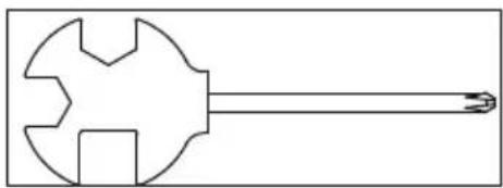
| Cross-end wrench S13-14-15 | 1 | |
| Spanner S6 | 1 | |
ASSEMBLY INSTRUCTION:
STEP 1:
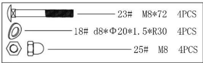
a. Attach front stabilizer (22) and rear stabilizer (26) to seat tube (30) with carriage bolts (23), arc washers (18) and domed nuts (25).
b. Attach pedal (28L/R) to the crank arms as shown above.
CAUTION: be sure the right pedal (28R) marked (R) is attached to the right crank arm and tightened in the counterclockwise direction.
The left pedal (28L) marked (L) is attached to the left crank arm and tightened in the anticlockwise direction.
natural_image
Pure mechanical component diagram without any text, numbers, or symbols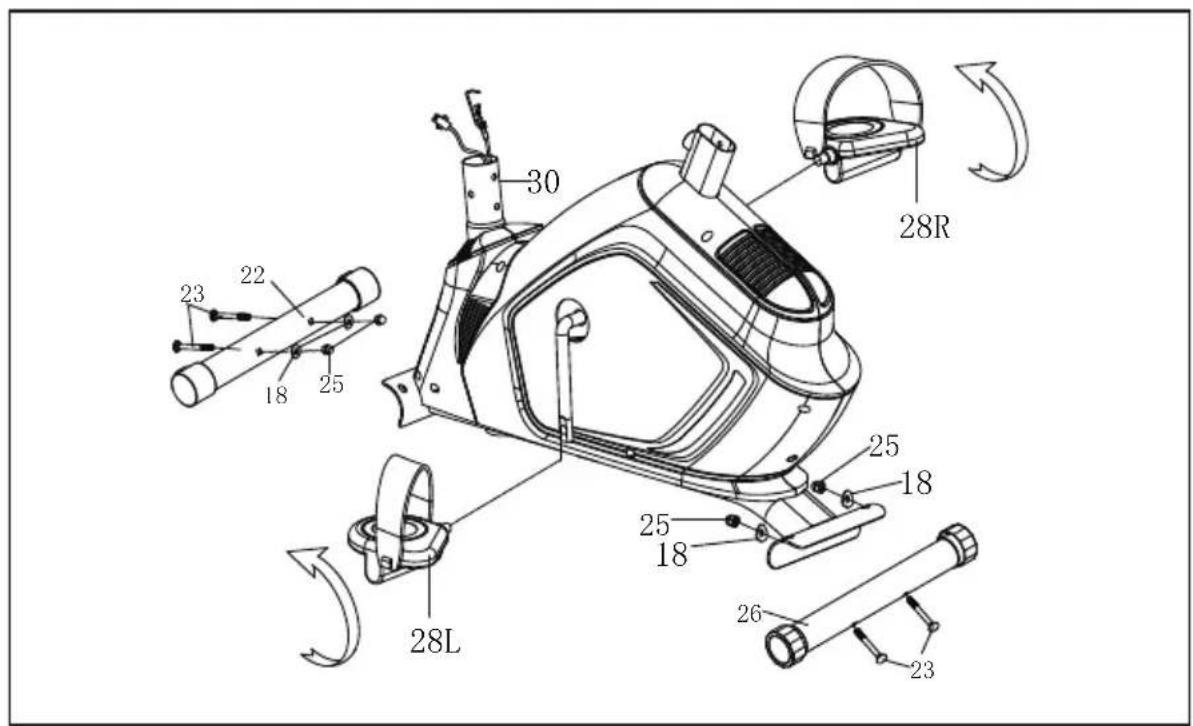
STEP 2:
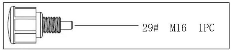
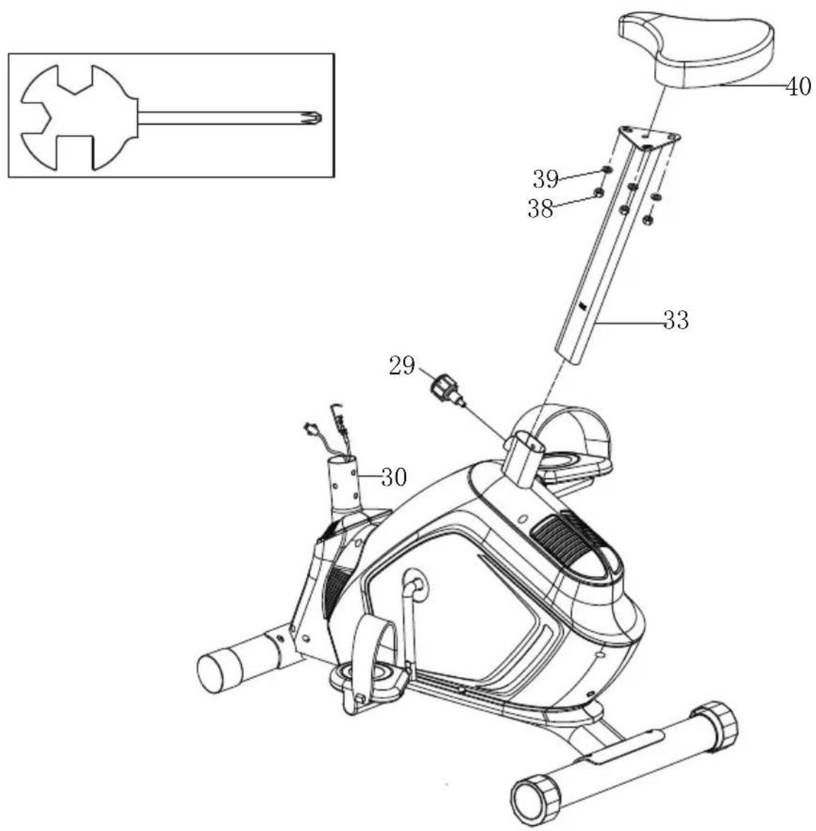
a. Attach seat (40) to sliding tube (33) with nylon nuts (38) and washers (39). b. Slide sliding tube (33) into seat tube (30). Secure and tighten with knob (29).
STEP 3:
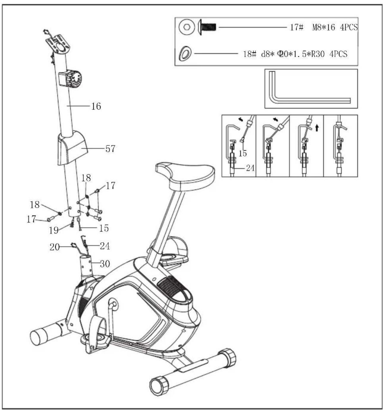
a. Attach front cover (57) to the support tube (16). Connect tension control (15) with tension wire (24). Connect sensor wire (20) with middle wire (19).
b. Attach support tube (16) to seat tube (30) with bolts (17) and arc washers (18).
STEP 4:
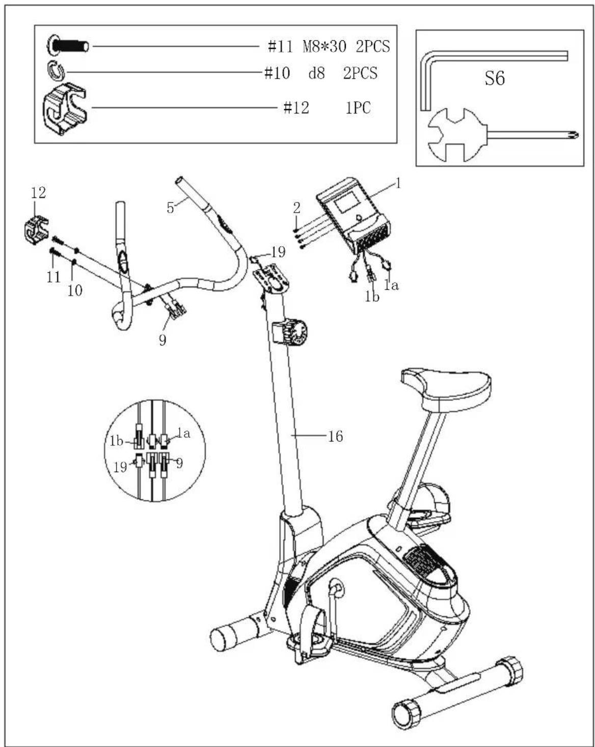
a. Attach handlebar (5) onto support tube (16) with screws (11), spring washers (10) and small cover (12). Then, get the pulse sensor wire (9) through the stopple.
b. Connect the pulse sensor wire (9) with electronic meter wire (1a). Connect the middle wire (19) with electronic meter wire (1b).
c. Attach electronic meter (1) to support tube (16) with screws (2) and washers (3).
The assembly is completed.
EXERCISE INSTRUCTIONS
Using your Upright BIKE provides you with several benefits, it will improve your physical fitness, tone muscle and in conjunction with calorie controlled diet help you lose weight.
1. The Warm Up Phase
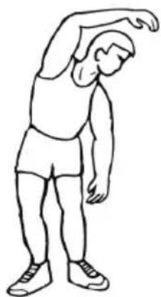
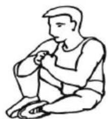
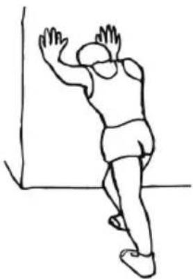
This stage helps get the blood flowing around the body and the muscles working properly. It will also reduce the risk of cramp and muscle injury. It is advisable to do a few stretching exercises as shown below. Each stretch should be held for approximately 30 seconds, do not force or jerk your muscles into a stretch - if it hurts, STOP.
natural_image
Line drawing of a person performing a forward bend stretch (no text or symbols)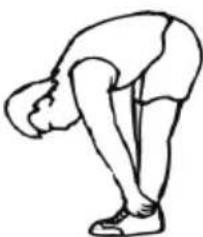
natural_image
Line drawing of a person bending forward with hands on hips (no text or symbols)FORWARD BENDS
natural_image
Line drawing of a person sitting cross-legged, holding an object (no text or symbols)INNER THIGH
natural_image
Simple line drawing of a person climbing a wall (no text or symbols)CALF / ANKLE
SIDE BENDS OUTER THIGH
2. The Exercise Phase
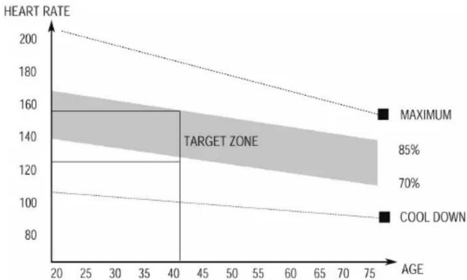
This is the stage where you put the effort in. After regular use, the muscles in your legs will become Stronger. Work to your routine, but it is very important to maintain a steady tempo throughout. The rate of workout should be sufficient to raise your heart beat into the target zone shown on the graph below.
line
| AGE | HEART RATE | | --- | --- | | 20 | 200 | | 40 | 160 | | 75 | 90 |This stage should last for a minimum of 12 minutes though most people start at about 15-20 minutes
3. The Cool Down Phase
This stage is to let your Cardio-vascular System and muscles wind down. This is a repeat of the warm up exercise e.g. reduce your tempo, continue for approximately 5 minutes. The stretching exercises should now be repeated, again remembering not to force or jerk your muscles into the stretch.
As you get fitter you may need to train longer and harder. It is advisable to train at least three times a week, and if possible space your workouts evenly throughout the week.
MUSCLE TONING
To tone muscle while on your Upright BIKE you will need to have the resistance set quite high. This will put more strain on our leg muscles and may mean you cannot train for as long as you would like. If you are also trying to improve your fitness you need to alter your training program. You should train as normal during the warm up and cool down phases, but towards the end of the exercise phase you should increase resistance, making your legs work harder than normal. You may have to reduce your speed to keep your heart rate in the target zone.
WEIGHT LOSS
The important factor here is the amount of effort you put in. The harder and longer you work the more calories you will burn. Effectively this is the same as if you were training to improve your fitness, the difference is the goal.
USE
The tension control knob allows you to alter the resistance of the pedals. A high resistance makes it more difficult to pedal, a low resistance makes it easier. For the best results, set the tension while the bike is in use.
EXERCISE MONITOR
SPECIFICATIONS:
TIME----00:00\~99:59MIN
SPEED----0.0\~99.9KM/H(ML/H)
DISTANCE----0.00\~999.9KM(ML)
ODOMETER----0.0\~9999KM or ML
PULSE 40\~240BPM
MODE: This key lets you to select and lock on to a particular function you want.
◆This system turns on when any key is pressed or when it receives an signal input from the speed sensor.
◆The system turns off automatically when the sensor has no signal input or no key operation for about 4 minutes.
2. RESET:
The unit can be reset by either changing battery or pressing the mode key for 3 seconds.
3.MODE:
To choose SCAN or LOCK if you do not want the scan mode, press the MODE key when the pointer starts blinking on the function you want.
4.FUNCTIONS:
- TIME: Press the MODE key until pointer locks on to TIME. The total working time will be shown when starting exercise.
2.SPEED: Press the MODE key until pointer locks on to SPEED. Displays current speed during workout time. - DISTANCE: Press the MODE key until pointer locks on to DISTANCE. The distance of each workout will be displayed when starting exercise.
- ODOMETER: Press the MODE key until the pointer advances to ODOMETER. The total accumulated distance will be shown.
5.CALORIE: Press the MODE key until pointer lock on to CALORIE. The calorie burned will be displayed when starting exercise.
6.(PULSE) : Press the MODE key until the pointer advances to PULSE function and put ear-clip to ear or take hold of the sensor with your hands for about 3 seconds, the pulse will be displayed.
SCAN: Display changes according to the next diagram every 4 seconds. Automatically display the following functions in the order shown:
TIME-SPEED-DISTANCE-CALORIE-PULSE
NOTE:
- If no signal appears in 4-5 minutes, the LCD display will be shut off automatically.
- When there is signal input, the monitor automatically turns on.
- If there is a possibility to see an improper display on the monitor, please replace the batteries to have a good result. You must be to replace the batteries at the same time.
- The monitor uses 1.5V "AA" or "AAA" batteries.
natural_image
Line drawing of a stationary exercise bike with adjustable arms and legs (no text or symbols)USER'S MANUAL/HANDBUCH/MANUEL DE L'UTILISATEUR /MANUAL DEL USUARIO/MANUALE UTENTE/INSTRUKCJA OBSŁUGI
Ellipsentrainer Maschine
SP37363
natural_image
Pure mechanical component diagram without any text, numbers, or symbols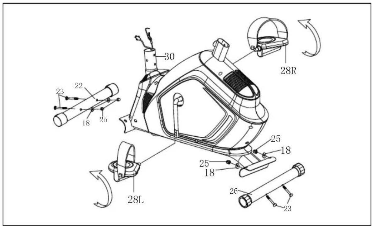
Schritt 2:
natural_image
Simple line drawing of a hammer-like tool with no text or symbols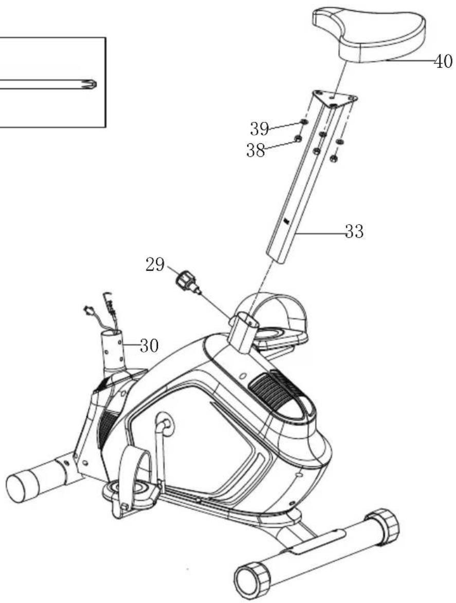
Schritt 3:
ÜBUNGSANLEITUNG:
natural_image
Line drawing of a stationary exercise bike with adjustable arms and legs (no text or symbols)USER'S MANUAL/HANDBUCH/MANUEL DE L'UTILISATEUR /MANUAL DEL USUARIO/MANUALE UTENTE/INSTRUKCJA OBSŁUGI
natural_image
Pure mechanical component diagram without any text, numbers, or symbols
ÉTAPE 2 :
ÉTAPE 3 :
line
| Age | RYTHME CARDIAQUE | | --- | --- | | 75 | 150 | | 40 | 120 | | 20 | 100 |3. Refroidissement
natural_image
Line drawing of a stationary exercise bike with adjustable arms and legs (no text or symbols)USER'S MANUAL/HANDBUCH/MANUEL DE L'UTILISATEUR /MANUAL DEL USUARIO/MANUALE UTENTE/INSTRUKCJA OBSŁUGI
| NÚM. | NOMBRE | CANTIDAD |
| 11422 | Medidor Electrónico | |
| 24431 | Tornillo de cruceta M5*10 | |
| 3/442 | ||
| 42452 | Espuma | |
| 51462 | Manillar | |
| 62471 | Tapa de extremo Φ25 | |
| 72481 | Sensor de pulso Φ25 | |
| 82492 | Tornillo de cruceta ST4,2*19 | |
| 92504 | Cable del sensor de pulso | |
| 10251 | Arandela clástica d8 | |
| 11252 | Tornillo M8*30 | |
| 12153 | Tapa pequeña | |
| 13154 | Tornillo de cruceta M5*25 | |
| 14155 | Arandela de arco d6*Φ20*R25*1,5 | |
| 15156 | Control de tensión | |
| 16157 | Tubo de soporte | |
| 17458 | Berno M8*16 | |
| 18859 | LARndela de arco d8*Φ20*1,5*R30 | |
| 19160 | Cable medio | |
| 20161 | Cable del sensor | |
| 21262 | Tapa de extremo Φ60 | |
| 22163 | Estabilizador delantero | |
| 23464 | Perno de carrocería M8*72 | |
| 24165 | Cable de tensión | |
| 25466 | Tuerca abovedada M8 | |
| 26167 | Estabilizador trasero | |
| 27268 | Tapa de extremo Φ60 | |
| 28L/R | Pedal L/ R | 1/1692 |
| 29170 | Perilla M16*1,5*Φ37 | |
| 30171 | Tubo de asiento | |
| 31272 | Tornillo de cruceta ST3,0*10 | |
| 32173 | Cojinete | |
| 33174 | Tubo deslizante | |
| 34/751 | ||
| 35/761 | ||
| 36/771 | ||
| 37/781 | ||
| 3831 | Tuerca de nailon M8 | |
| 3931 | Arandela d8*Φ20*1,5 | |
| 40 | Asiento | 1 |
| 41 | Perno hexagonal M6*30 | 1 |
natural_image
Pure mechanical component diagram without any text, numbers, or symbols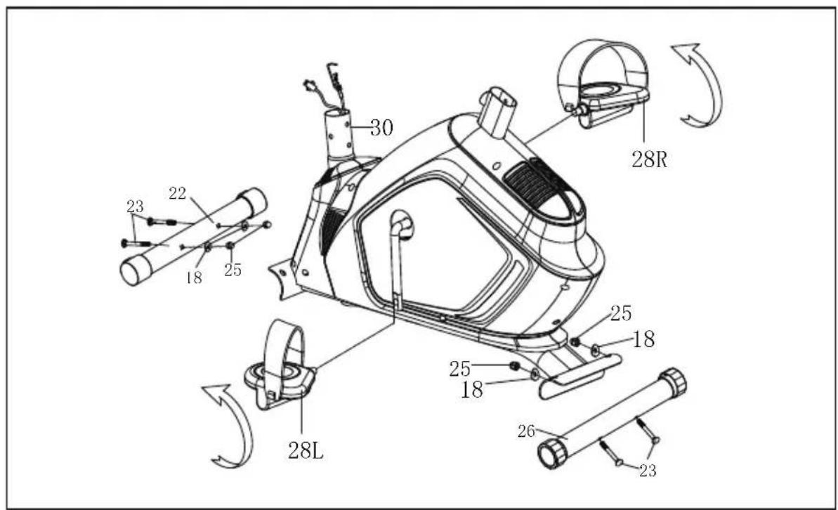
PASO 2:
PASO 3:
natural_image
Line drawing of a stationary exercise bike with adjustable arms and legs (no text or symbols)USER'S MANUAL/HANDBUCH/MANUEL DE L'UTILISATEUR /MANUAL DEL USUARIO/MANUALE UTENTE/INSTRUKCJA OBSŁUGI
natural_image
Pure electrical circuit lines without any symbols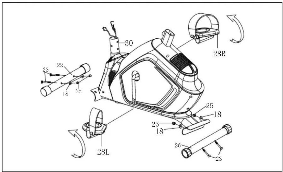
Passo 2:
Passo 3:
natural_image
Line drawing of a stationary exercise bike with adjustable arms and legs (no text or symbols)USER'S MANUAL/HANDBUCH/MANUEL DE L'UTILISATEUR /MANUAL DEL USUARIO/MANUALE UTENTE/INSTRUKCJA OBSŁUGI
natural_image
Pure mechanical component diagram without any text, numbers, or symbols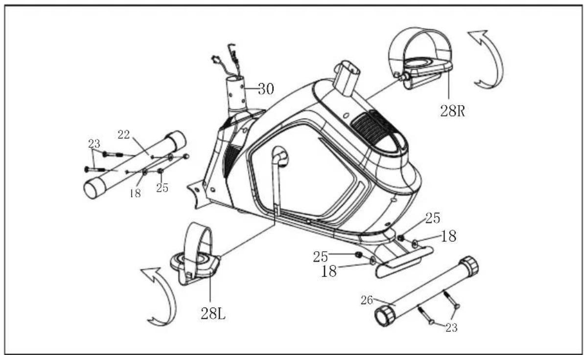
KROK 2:
natural_image
Simple line drawing of a hammer-like tool with no text or symbols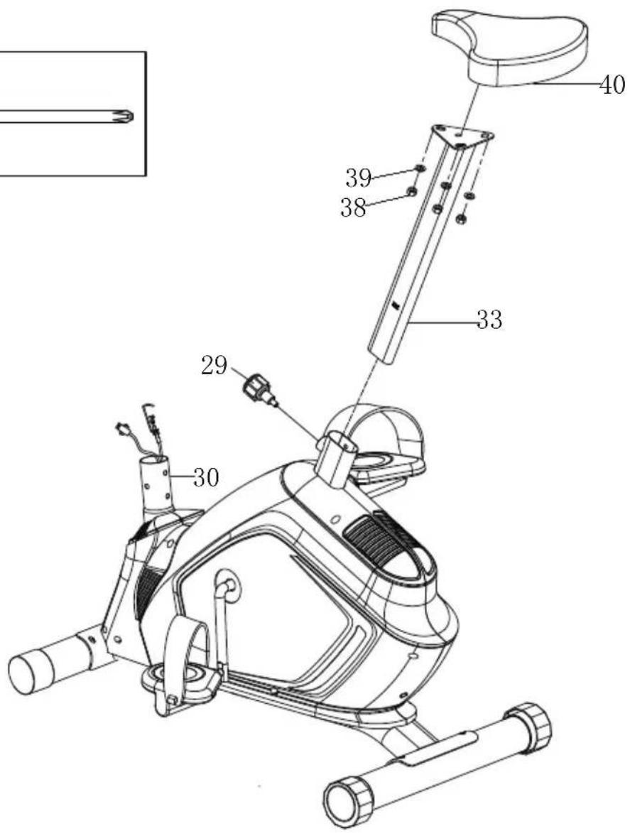
KROK 3:
With your inspiring rating, COSTWAY will be more consistent to offer you EASY SHOPPING EXPERIENCE, GOOD PRODUCTS and EFFICIENT SERVICE!
- USER'S MANUAL/HANDBUCH/MANUEL DE L'UTILISATEUR /MANUAL DEL USUARIO/MANUALE UTENTE/INSTRUKCJA OBSŁUGI
- DEAR CUSTOMER,
- PLEASE READ THIS INSTRUCTION VERY CAREFULLY BEFORE USING THE ITEM.
- IMPORTANT SAFETY NOTICE:
- ASSEMBLY INSTRUCTION:
- STEP 1:
- STEP 2:
- STEP 3:
- STEP 4:
- The assembly is completed.
- EXERCISE INSTRUCTIONS
- The Warm Up Phase
- The Exercise Phase
- The Cool Down Phase
- MUSCLE TONING
- WEIGHT LOSS
- USE
- EXERCISE MONITOR
- SPECIFICATIONS:
- RESET:
- 3.MODE:
- 4.FUNCTIONS:
- TIME-SPEED-DISTANCE-CALORIE-PULSE
- NOTE:
- Schritt 2:
- Schritt 3:
- ÜBUNGSANLEITUNG:
- ÉTAPE 2 :
- ÉTAPE 3 :
- Refroidissement
- PASO 2:
- PASO 3:
- Passo 2:
- Passo 3:
- KROK 2:
- KROK 3:
Brand : COSTWAY
Model : SP37363
Category : Indoor bike trainer