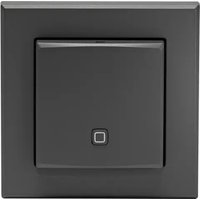
HmIP-STH-A - Humidifier Homematic IP - Free user manual and instructions
Find the device manual for free HmIP-STH-A Homematic IP in PDF.


User questions about HmIP-STH-A Homematic IP
0 question about this device. Answer the ones you know or ask your own.
Ask a new question about this device
Download the instructions for your Humidifier in PDF format for free! Find your manual HmIP-STH-A - Homematic IP and take your electronic device back in hand. On this page are published all the documents necessary for the use of your device. HmIP-STH-A by Homematic IP.
USER MANUAL HmIP-STH-A Homematic IP
natural_image
Close-up of a white square electrical switch with a small blue square button on the left side (no text or symbols visible)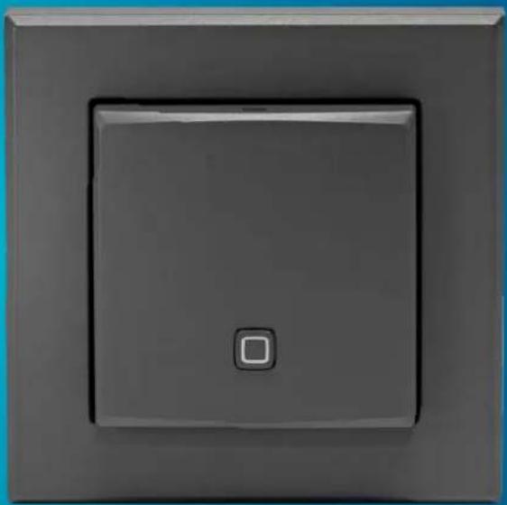
natural_image
Close-up of a gray square electrical switch with a small square button on the side (no text or symbols visible)EN Installation and operating manual
natural_image
Line drawing of a hand holding a wall-mounted device with blue directional arrows indicating rotation (no text or symbols)Abbildung 2
natural_image
Line drawing of a hand pressing a square button on a wall-mounted panel (no text or symbols)Abbildung 3
text_image
E F >P0C ?A86< FAbbildung 4
natural_image
Pure electrical circuit lines without any symbolsAbbildung 6
natural_image
Line drawing of a hand holding a wall-mounted device with blue arrows indicating rotation or movement (no text or symbols)Abbildung 7
natural_image
Line drawing of hands installing a battery component into a housing (no text or symbols)Abbildung 8
1 Package contents....16
2 Information about this manual....16
3 Hazard information ....16
4 Function and device overview....17
5 General system information 17
6 Start-up....18
6.1 Pairing 18
6.2 Installation....19
6.2.1 Adhesive strip mounting 19
6.2.2 Screw mounting....20
6.2.3 Mounting on flush-mounted boxes....20
6.2.4 Installation in multiple combinations 21
7 Changing the batteries 22
8 Troubleshooting....23
8.1 Low battery 23
8.2 Command not confirmed 23
8.3 Duty Cycle 23
8.4 Error codes and flashing sequences 24
9 Restoring factory settings 25
10 Maintenance and cleaning....25
11 General information about radio operation 25
12 Disposal.... 26
13 Technical specifications....27
1 Package contents
1x Temperature and Humidity Sensor – indoor
1x Clip-on frame
1x Mounting plate
2x Double-sided adhesive strips
2x Screws 3.0 x 30 mm
2x Plugs 5 mm
2x 1.5 V LR03/micro/AAA batteries
1x Operating manual
2 Information about this manual
Please read this manual carefully before operating your Homematic IP components. Keep the manual so you can refer to it at a later date if you need to. If you hand over the device to other persons for use, please hand over this manual as well.
Symbols used:

Attention!
This indicates a hazard.

Note. This section contains important additional information!
3 Hazard information

Caution! There is a risk of explosion if the batteries are not replaced correctly. Replace only with the same or equivalent type. Never recharge non-rechargeable batteries. Do not throw the batteries into a fire. Do not expose batteries to excessive heat. Do not short-circuit batteries. Doing so will present a risk of explosion!

Contact with batteries that are dead or damaged can cause skin irritation. Use protective gloves in this case.

Do not open the device. It does not contain any parts that need to be maintained by the user. In the event of an error, please have the device checked by an expert.

For safety and licensing reasons (CE), unauthorized change and/or modification of the device is not permitted.

The device may only be operated in dry and dust-free environment and must be protected from the effects of moisture, vibrations, solar or other methods of heat radiation, cold and mechanical loads.

The device is not a toy: do not allow children to play with it. Do not leave packaging material lying around. Plastic films/bags, pieces of polystyrene, etc. can be dangerous in the hands of a child.

We accept no liability for damage to property or personal injury caused by improper use or failure to observe the hazard warnings. In such cases, all warranty claims are void. We accept no liability for any consequential damage.

The device must only be operated within residential buildings.

Using the device for any purpose other than that described in this operating manual does not fall within the scope of intended use and will invalidate any warranty or liability.
4 Function and device overview
The Homematic IP Temperature and Humidity Sensor - indoor measures the temperature and humidity in the room. The measured values are transferred cyclically to the Homematic IPAccess Pointaswellas to the Homematic IP app and help to regulate the room climate. Take a look at the homescreen of the app and you will be informed about the temperature as well as the current humidity of the corresponding room. Thanks to radio operation, the device is highly flexible where mounting and selecting a mounting location are concerned. The device is mounted and removed very easily with the supplied clip-on frame using screws or adhesive strips. It is compatible with a number of different surfaces including furniture, brick walls, tiles or glass. It is possible to integrate the temperature and humidity sensor into existing switches of leading manufacturers.
Device overview:
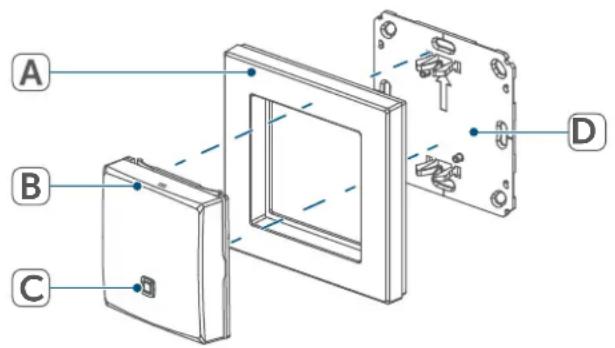
(A) Clip-on frame
(B) Sensor (electronic unit)
(C) System button (pair button and LED)
(D) Mounting plate
(E) Adhesive strips
(F) Letters
(G) Holes
(H) Bore holes
text_image
A B C DFigure 1
5 General system information
This device is part of the Homematic IP smart home system and works with the Homematic IP radio protocol. All devices of the system can be configured comfortably and individually with the Homematic IP smartphone app. Alternatively, you can operate the Homematic IP devices via the Homematic Central Control Unit CCU3 or in connection with various partner solutions. The available functions provided by the system in combination with other components are described in the Homematic IP User Guide. All current technical documents and updates are provided at
www.homematic-ip.com.
6 Start-up
6.1 Pairing

Please read this entire section before starting the pairing procedure.

First set up your Homematic IP Access Point via the Homematic IP apptoenableoperation of other Homematic IP devices within your system. For further information, please refer to the operating manual of the Access Point.

For more information on teaching and setting up the wall thermostat using a CCU3, please refer to the WebUI manual on our homepage at www.homematic-ip.com.
To integrate the temperature and humidity sensor into your system and enable it to communicate with other Homematic IP devices, you must pair the device to your Homematic IPAccess Pointfirst.
To pair the temperature and humidity sensor, please proceed as follows:
- OpentheHomematic IP appon your smartphone.
- Select the menu item "Pair device".
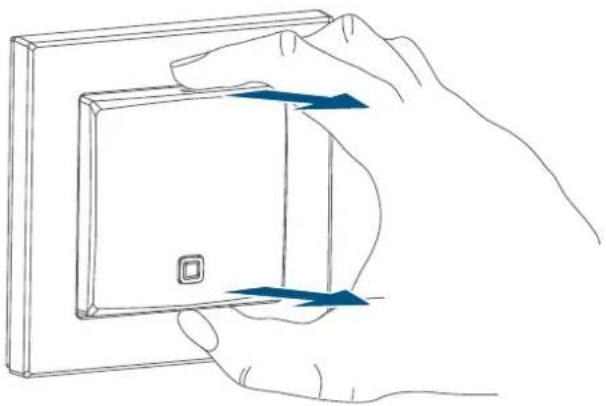
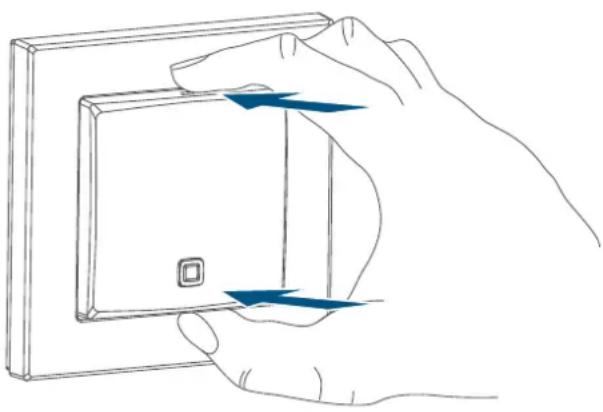
- To remove the sensor (B) from the frame, take hold of the sides of the sensor and pull it out.
natural_image
Hand holding a wall-mounted device with blue directional arrows indicating rotation or movement (no text or symbols)Figure 2
- Turn over the sensor.
- Remove the insulation strip from the battery compartment. Pairing mode remains activated for 3 minutes.

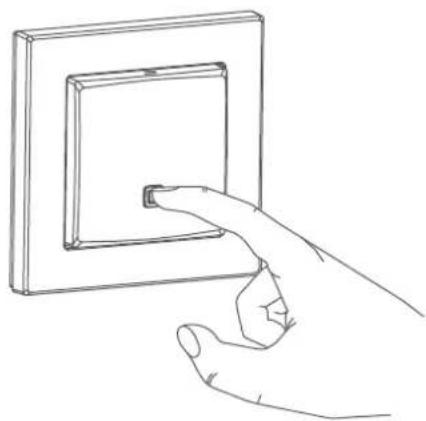
You can manually start the pair mode for another 3 minutes by pressing the system button (C) shortly.
natural_image
Line drawing of a hand pressing a square button on an electrical wall (no text or symbols)Figure 3
Your device will automatically appear intheHomematic IP App.
- To confirm, please enter the last four digits of the device number (SGTIN) in your app or scan the QR code. Therefore, please see the sticker supplied or attached to the device.
- Please wait until pairing is completed.
- If pairing was successful, the LED lights up green. The device is now ready for use.
- If the LED lights up red, please try again.
- Please select in which application you want to use the device.
- Allocate the device to a room and give the device a name.
6.2 Installation

Please read this entire section before starting to mount the device.
You can use the supplied clip-on frame (A) to mount the temperature and humidity sensor or easily integrate it into an existing switch (see „6.2.4 Installation in multiple combinations“ on page 21).
If you want to mount the temperature and humidity sensor with the supplied clip-on frame, you can use
- the supplied double-sided adhesive strips or
• the supplied screws
to fix it to a wall.
You can also mount the temperature and humidity sensor on a flush-mounting box.
6.2.1 Adhesive strip mounting
For mounting the assembled device with adhesive strips, please proceed as follows:
- Choose a site for installation.

Make sure that the mounting surface is smooth, solid, non-disturbed, free of dust, grease and solvents and not too cold to ensure ong-time adherence.
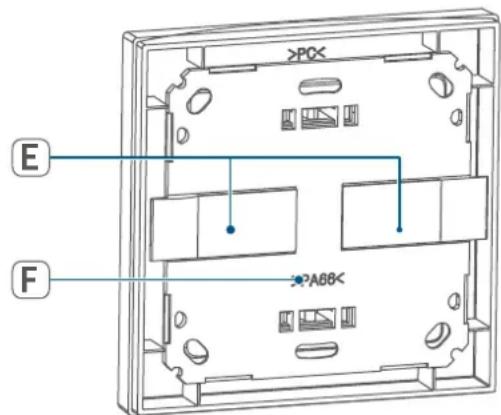
- Fix the adhesive strips (E) on the back side of the mounting plate (D) in the provided area. You should be able to read the letters on the back side (F).
text_image
>PC E F A88Figure 4
- Remove the protective film from the adhesive strips.
- Press the assembled temperature and humidity sensor with the back side to the wall in the position where it should subsequently be attached.
6.2.2 Screw mounting
For mounting the temperature and humidity sensor with the supplied screws, please proceed as follows:
- Choose a site for installation.

Make sure that no electricity or similar lines run in the wall at this location!
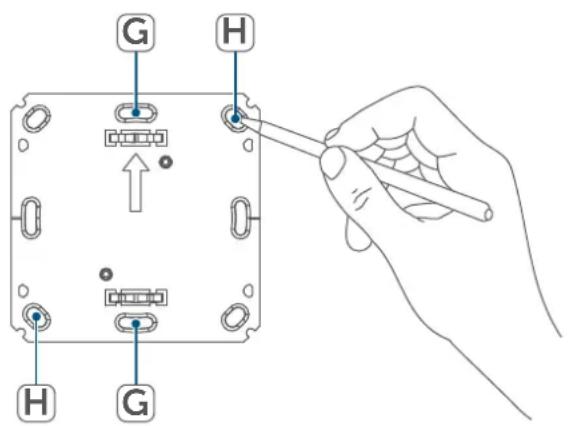
- Position the mounting plate (D) on the desired site on the wall. Make sure that the arrow on the mounting plate is pointing upwards.
- Use a pen to mark the positions of bore holes (H) (diagonally opposite) in the mounting plate on the wall.
text_image
G H H GFigure 5
- Now drill the bore holes.

If you are working with a stone wall, drill the marked two 5 mm holes and insert the plugs supplied. If you are working with a wooden wall, you can pre-drill 1.5 mm holes to make screws easier to insert.
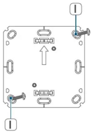
- Use the supplied screws and plugs (I) to fasten the mounting plate to the wall.
natural_image
Pure electrical circuit lines without any symbolsFigure 6
- Attach the clip-on frame (A) to the mounting plate.
- Place the sensor (B) back into the frame. Make sure that the clips on the mounting plate latch into the openings on the sensor.
natural_image
Line drawing of a hand holding a wall-mounted device with blue arrows indicating rotation or force (no text or symbols)Figure 7
6.2.3 Mounting on flush-mounted boxes
You can mount the temperature and humidity sensor on flush-mounting/installation boxes using the holes (G). ( see figure).

If the device is mounted to a flush-mounting box, there may be no open conductor ends.

If changes or works have to be made on the house installation (e.g. extension, bypass of switch-or socket inserts) or the low-voltage distribution for mounting or installing the device, the following safety instruction must be considered:

Please note! Only to be installed by persons with the relevant electro-technical knowledge and experience!*
Incorrect installation can endanger
- your own life,
- and the lives of other users of the electrical system.
Incorrect installation also means that you are running the risk of serious damage to property, e.g. because of a fire. You may be personally liable in the event of injuries or damage to property.
Consult an electrician!
*Specialist knowledge required for installation:
The following specialist knowledge is particularly important during installation:
- The "5 safety rules" to be used: Disconnect from mains; Safeguard from switching on again; Check that system is deenergised; Earth and short circuit; Cover or cordon
off neighbouring live parts;
- Select suitable tool, measuring equipment and, if necessary, personal safety equipment;
- Evaluation of measuring results;
- Selection of electrical installation material for safeguarding shut-off conditions;
- IP protection types;
• Installation of electrical installation material; - Type of supply network (TN system, IT system, TT system) and the resulting connecting conditions (classical zero balancing, protective earthing, required additional measures etc.).
6.2.4 Installation in multiple combinations
You can mount the temperature and humidity sensor with the attachment frame (A) provided or use it with 55 mm frames of other manufacturers as well as integrate the electronic unit (B) into a multi-gang frame. You can flexibly fix the mounting plate (D) to the wall using adhesive strips or screws. For mounting with multiple combinations, make sure that the mounting plate of the temperature and humidity sensor is seamlessly aligned to the already fixed mounting plate/retaining ring.
The temperature and humidity sensor is designed to fit into 55 mm frames supplied by the following manufacturers:
| Manufacturer | Frame |
| Berker S.1, B.1, | B.3, B.7 glass |
| ELSO Joy | |
| GIRA | System 55, Standard 55, E2, E22, Event, Esprit |
| merten | 1-M, Atelier-M, M-Smart,M-Arc, M-Star,M-Plan |
| JUNG | A 500, AS 500, A plus, A creation |
7 Changing the batteries
If an empty battery is displayed via the app or the device (see „8.4 Error codes and flashing sequences“ on page 24), replace the used batteries by two new LR03/micro/AAA batteries. You must observe the correct battery polarity.
To replace the batteries of the temperature and humidity sensor, please proceed as follows:
- Once mounted, the sensor can easily be pulled out of the frame (A) or removed from the mounting plate (D). To remove the sensor (B) from the frame, take hold of the sides of the sensor and pull it out. (→see figure). You do not need to open the device.
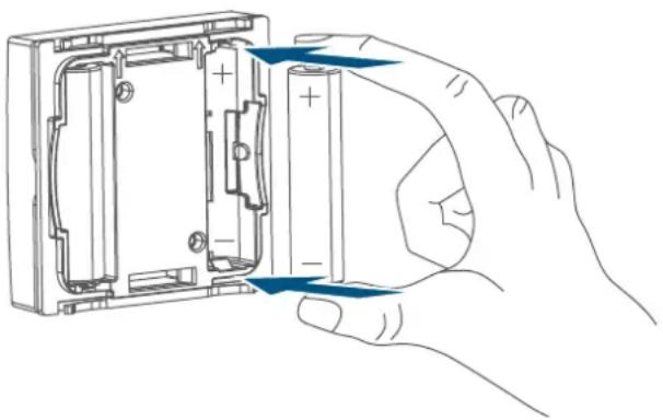
- Turn the sensor over to remove the batteries.
- Insert two new 1.5 V LR03/micro/batteries into the battery compart-
ment, making sure that you insert them the right way round.
natural_image
Hand inserting a battery into a housing panel (no text or symbols visible)Figure 8
- Put the sensor back into the frame. Make sure that the clips on the mounting plate latch into the openings on the sensor.
- Please pay attention to the flashing signals of the device LED while inserting the batteries (see „8.4 Error codes and flashing sequences“ on page 24).
Once the batteries have been inserted, the temperature and humidity sensor will perform a self-test/restart (approx. 2 seconds). Afterwards, initialisation is carried out. The LED test display will indicate that initialisation is complete by lighting up orange and green.

Caution! There is a risk of explosion if the battery is not replaced correctly. Replace only with the same or equivalent type. Never recharge standard batteries. Do not throw the batteries into a fire. Do not expose batteries to excessive heat. Do not short-circuit batteries. Doing so will present a risk of explosion.
8 Troubleshooting
8.1 Low battery
Provided that the voltage value permits it, the temperature and humidity sensor will remain ready for operation also if the battery voltage is low. Depending on the particular load, it may be possible to send transmissions again repeatedly, once the batteries have been allowed a brief recovery period.
If the voltage drops too far during transmission, this will be displayed on the device or via the Homematic IP app (see „8.4 Error codes and flashing sequences“ on page 24). In this case, replace the empty batteries by two new batteries (see „7 Changing the batteries“ on page 22).
8.2 Command not confirmed
If at least one receiver does not confirm a command, the device LED lights up red at the end of the failed transmission process. The failed transmission may be caused by radio interference (see „11 General information about radio operation“ on page 25). This may be caused by the following:
- Receiver cannot be reached.
- Receiver is unable to execute the command (load failure, mechanical blockade, etc.).
- Receiver is defective.
8.3 Duty Cycle
The duty cycle is a legally regulated limit of the transmission time of devices in the 868 MHz range. The aim of this regulation is to safeguard the operation of all devices working in the 868 MHz range.
In the 868 MHz frequency range we use, the maximum transmission time of any device is 1% of an hour (i.e. 36 seconds in an hour). Devices must cease transmission when they reach the 1% limit until this time restriction comes to an end. Homematic IP devices are designed and produced with 100% conformity to this regulation.
During normal operation, the duty cycle is not usually reached. However, repeated and radio-intensive pair processes mean that it may be reached in isolated instances during start-up or initial installation of a system. If the duty cycle is exceeded, this is indicated by one long flashing of the device LED, and may manifest itself in the device temporarily working incorrectly. The device starts working correctly again after a short period (max. 1 hour).
8.4 Error codes and flashing sequences
| Flashing code Meaning Solution | ||
| Short orange flashing | Radio transmission/attempting to transmit/data transmission | Wait until the transmission is completed. |
| 1x long green lighting Transmission confirmed | You can continue operation. | |
| 1x long red lighting Transmission failed | Please try again (see „8.2 Command not confirmed" on page 23). | |
| Short orange lighting (after green or red confirmation) | Batteries empty | Replace the batteries of the device (see „7 Changing the batteries" on page 22). |
| Short orange flashing (every 10 s) | Pair mode active | Please enter the last four numbers of the device serial number to confirm (see „6.1 Pairing" on page 18). |
| 1x long red lighting | Transmission failed or duty cycle limit is reached | Please try again (see „8.2 Command not confirmed" on page 23) or (see „8.3 Duty Cycle" on page 23). |
| 6x long red flashing Device | defective | Please see your app for error message or contact your retailer. |
| 1x orange and 1 x green lighting (after inserting batteries) | Test display | Once the test display has stopped, you can continue. |
9 Restoring factory settings

The factory settings of the device can be restored. If you do this, you will lose all your settings.
To restore the factory settings of the temperature and humidity sensor please proceed as follows:
- To remove the sensor (B) from the frame, take hold of the sides of the sensor and pull it out. (→see figure).
- Remove one battery.
- Insert the battery ensuring that the polarity is correct while pressing ( see figure) and holding down the system button (C) for 4s at the same time, until the LED will quickly start flashing orange ( see figure).
- Release the system button again.
- Press and hold down the system button again for 4 seconds, until the status LED lights up green.
- Release the system button to finish the procedure.
The device will perform a restart.
10 Maintenance and cleaning

The device does not require you to carry out any maintenance other than replacing the battery when necessary. Enlist the help of an expert to carry out any maintenance or repairs.
Clean the device using a soft, lint-free cloth that is clean and dry. You may dampen the cloth a little with lukewarm water in order to remove more stubborn marks. Do not use any detergents containing solvents, as they could corrode the plastic housing and label.
11 General information about radio operation
Radio transmission is performed on a non-exclusive transmission path, which means that there is a possibility of interference occurring. Interference can also be caused by switching operations, electrical motors or defective electrical devices.

The range of transmission within buildings can differ greatly from that available in the open air. Besides the transmitting power and the reception characteristics of the receiver, environmental factors such as humidity in the vicinity have an important role to play, as do on-site structural/screening conditions.
eQ-3 AG, Maiburger Straße 29, 26789 Leer, Germany hereby declares that the radio equipment type Homematic IP HmIP-STH, HmIP-STH-A is compliant with Directive 2014/53/EU. The full text of the EU declaration of conformity is available at the following internet address: www.homematic-ip.com
12 Disposal
Instructions for disposal

This symbol means that the device and the batteries or accumulators must not be disposed of with household waste, the residual waste bin or the yellow bin or yellow bag. For the protection of health and the environment, you must take the product, all electronic parts included in the scope of delivery, and the batteries to a municipal collection point for old electrical and electronic equipment to ensure their correct disposal. Distributors of electrical and electronic equipment or batteries must also take back obsolete equipment or batteries free of charge.
By disposing of it separately, you are making a valuable contribution to the reuse, recycling and other methods of recovery of old devices and old batteries.
You must separate any old batteries and accumulators of old electrical and electronic devices from the old device if they are not enclosed by the old device before handing it over to a collection point and to dispose of them separately at the local collection points. Please also remember that you, the end user, are responsible for deleting personal data on any old electrical and electronic equipment before disposing of it.
Information about conformity

The CE mark is a free trademark that is intended exclusively for the authorities and does not imply any assurance of properties.

For technical support, please contact your retailer.
13 Technical specifications
Device short description: HmIP-STH, HmIP-STH-A
Supply voltage: 2x 1.5 V LR03/micro/AAA
Current consumption: 20 mA max.
Battery life: 2 years (typ.)
Degree of protection: IP20
Ambient temperature: 5 to 35 °C
Dimensions (W x H x D):
Without frame: 55 x 55 x 19 mm
Including frame: 86 x 86 x 20 mm
Weight: 85 g (including batteries)
Radio frequency band: 868.0–868.6 MHz
869.4–869.65 MHz
Maximum radiated power: 10 dBm
Receiver category: SRD category 2
Typ. open area RF range: 130 m
Duty cycle: < 1 % per h/< 10 % per h
Subject to technical changes.
Table des matières
natural_image
Hand holding a wall-mounted device with blue directional arrows indicating rotation or movement (no text or symbols)Figure 2
natural_image
Line drawing of a hand inserting a small component into a square electrical outlet (no text or symbols)Figure 3
text_image
>POX E F ?A88Figure 4
natural_image
Pure electrical circuit lines without any symbolsFigure 6
natural_image
Line drawing of a hand holding a wall-mounted device with blue arrows indicating rotation or force (no text or symbols)Figure 7
natural_image
Hand holding a battery pack with arrows indicating direction of movement (no text or symbols)Figure 8
Poids : 85 g (piles comprises)
natural_image
Hand holding a wall-mounted device with blue arrows indicating rotation or movement (no text or symbols)Figura 2
natural_image
Line drawing of a hand pressing a square button on an electrical wall (no text or symbols)Figura 3
natural_image
Pure electrical circuit lines without any symbolsFigura 6
natural_image
Line drawing of a hand holding a wall-mounted device with blue arrows indicating rotation or movement (no text or symbols)Figura 7
natural_image
Hand holding a battery pack with arrows indicating direction of movement (no text or symbols)Figura 8
natural_image
Line drawing of a hand holding a wall-mounted device with blue arrows indicating direction (no text or symbols)Figura 2
natural_image
Line drawing of a hand pressing a square button on an electrical wall (no text or symbols)Figura 3
natural_image
Pure electrical circuit lines without any symbolsFigura 6
natural_image
Line drawing of a hand holding a wall-mounted panel with two blue arrows indicating direction (no text or symbols)Figura 7
natural_image
Line drawing of hands assembling a battery into a housing (no text or symbols)Figura 8
Dimensioni (L x A x P):
Senza telaio: 55 x 55 x 19 mm
natural_image
Line drawing of a hand holding a wall-mounted device with blue directional arrows indicating rotation (no text or symbols)Afbeelding 2
natural_image
Line drawing of a hand pressing a square button on an electrical wall (no text or symbols)Afbeelding 3
text_image
E F >POX >A08Afbeelding 4
natural_image
Pure electrical circuit lines without any symbolsAfbeelding 6
natural_image
Line drawing of a hand holding a wall-mounted device with blue arrows indicating rotation or movement (no text or symbols)Afbeelding 7
natural_image
Hand holding a battery pack with arrows indicating direction of movement (no text or symbols)Afbeelding 8
Free download of the Homematic IPapp!

text_image
Blue QR code image, scannable for digital content retrieval
Download on the
App Store

text_image
Blue QR code image, scannable for digital content retrieval
GET IT ON
Google Play
Bevollmächtigter des Herstellers: Manufacturer's authorised representative

eQ-3 AG
Maiburger Straße 29
26789 Leer / GERMANY
www.eQ-3.de
