ColdMachine VD-08 - Freezer DOMETIC - Free user manual and instructions
Find the device manual for free ColdMachine VD-08 DOMETIC in PDF.

| Product type | Freezer |
| Brand | Dometic |
| Model | ColdMachine VD-08 |
| Supply voltage | 12 V DC or 24 V DC |
| Max compartment volume (35 mm insulation) | 160 litres |
| Max compartment volume (50 mm insulation) | 180 litres |
| Power consumption | 45 W |
| Dimensions (W x H x D) | 450 x 270 x 340 mm |
| Weight | 2.0 kg |
| Refrigerant | R-134a (GWP 1430) |
| Refrigerant charge | 45 g |
| Main functions | Refrigeration and freezing, electronic battery protection (shutdown at 10.4 V/22.8 V, restart at 11.7 V/24.2 V) |
| Use on boats | Yes, withstands permanent heel up to 30° |
| Installation | Requires installation in an insulated container (min. 35 mm polyurethane foam thickness) |
| Recommended accessories | Rectifier CoolPower EPS100, MPS35 or MPS50 for 230 V AC power supply |
| Cleaning and maintenance | Regularly clean the condenser, defrost the evaporator if frost appears, use a damp cloth without abrasive products |
| Safety | Reverse polarity protection, automatic shutdown in case of undervoltage, do not open the refrigeration circuit |
| Repairability | Repairs reserved for qualified technician; spare parts available from the manufacturer |
Frequently Asked Questions - ColdMachine VD-08 DOMETIC
User questions about ColdMachine VD-08 DOMETIC
0 question about this device. Answer the ones you know or ask your own.
Ask a new question about this device
Download the instructions for your Freezer in PDF format for free! Find your manual ColdMachine VD-08 - DOMETIC and take your electronic device back in hand. On this page are published all the documents necessary for the use of your device. ColdMachine VD-08 by DOMETIC.
USER MANUAL ColdMachine VD-08 DOMETIC
natural_image
Interior view of an electric appliance showing internal components and wiring (no visible text or symbols)ColdMachine 50, 54, 55, 84, 85, 86, 94, 95, 96, CS-NC15 VD-01, VD-02, VD-03, VD-04, VD-05, VD-06, VD-07, VD-08, VD-09, VD-14N, VD-15, VD-16, VD-18, VD-21
EN Cooling unit
Installation and Operating Manual.....13
DE Kühlaggregat
© 2021 Dometic Group. The visual appearance of the contents of this manual is protected by copyright and design law. The underlying technical design and the products contained herein may be protected by design, patent or be patent pending. The trademarks mentioned in this manual belong to Dometic Sweden AB. All rights are reserved.
1
2
3
VD-01, VD-04, VD-08
natural_image
Technical line drawing of a mechanical bracket or mounting bracket with hatched walls and a central support (no text or symbols)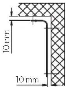
4
VD-03
natural_image
Isometric line drawing of a 3D cube containing a rectangular container with a mesh pattern and a small internal component (no text or symbols)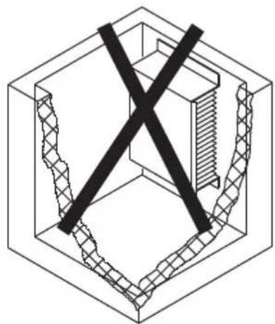
natural_image
Isometric line drawing of a mechanical component with a central X mark and textured base (no text or symbols)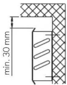
5
VD-02, VD-05, VD-18, VD-21
natural_image
Isometric line drawing of a door frame with a square panel and mounting holes, no text or symbols present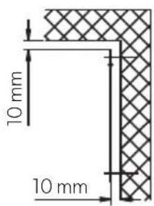

13
14
A

B
natural_image
Diagram of a kitchen sink and door with directional arrows indicating movement or force (no text or symbols)C
natural_image
Diagram of a microwave oven inside a transparent enclosure, showing airflow direction (no text or labels)D
natural_image
Diagram of a kitchen appliance with a piping system and directional arrows indicating movement (no text or symbols)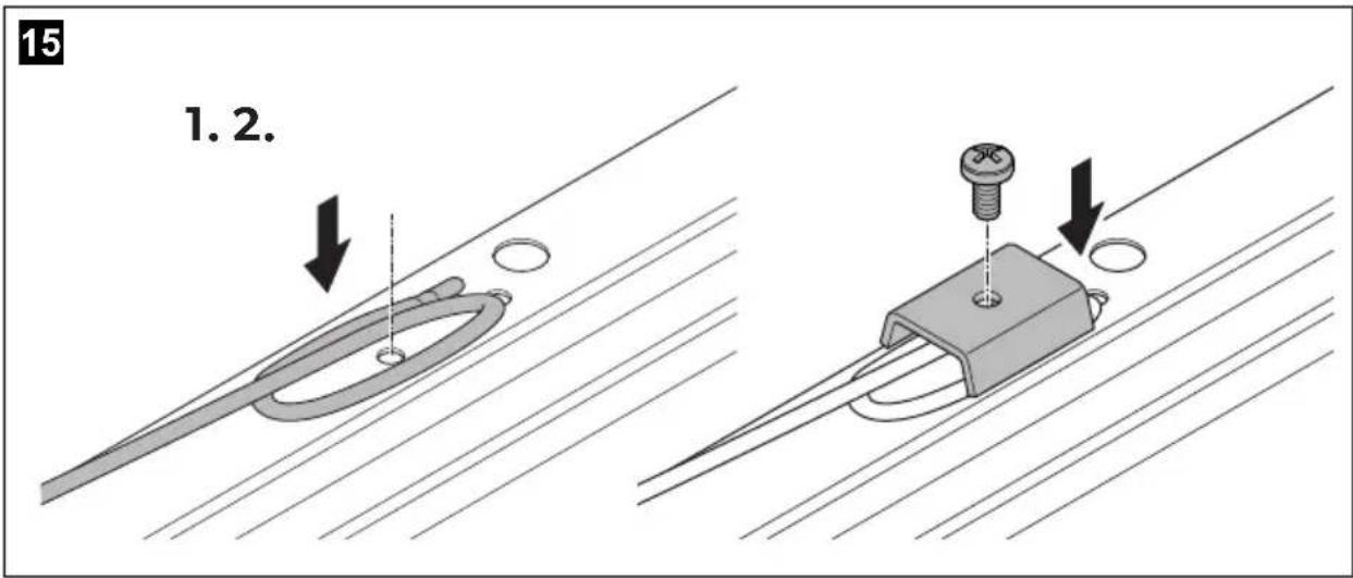
19
VD-01, VD-02, VD-03, VD-04, VD-05,
VD-07, VD-08, VD-09, VD-18, VD-21
20
VD-06
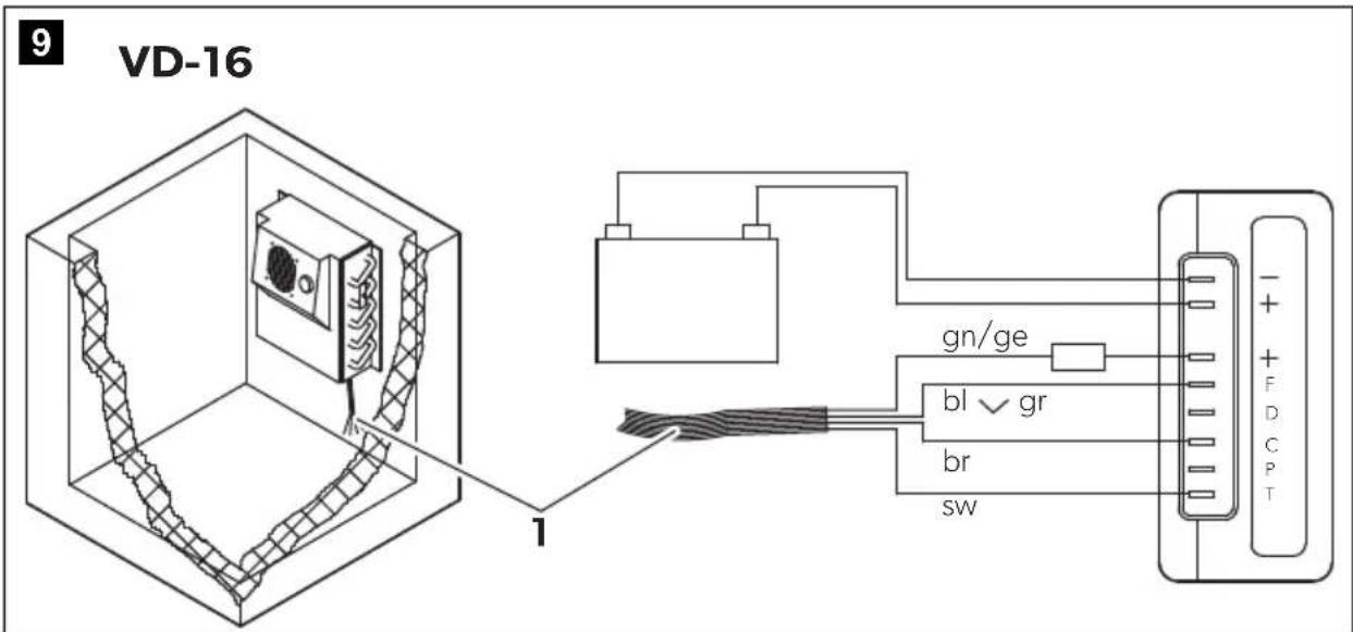
| bl br ge | gn gr rt sw ws v | ||||||||
| EN | Blue Brown Yellow | Green Grey | Red Black White or | ||||||
| DE | Blau | Braun | Gelb | Grün | Grau | Rot | Schwarz | Weiss | oder |
| FR | Bleu | Marron | Jaune | Vert | Gris | Rouge | Noir | Blanc | ou |
| ES | Azul | Marrón | Amarillo | Verde | Gris | Rojo | Negro | Blanco | o bien |
| PT | Azul | Castanho | Amarelo | Verde | Cinzento | Vermelho | Preto | Branco | ou |
| IT | Blu | Marrone | Giallo | Verde | Grigio | Rosso | Nero | Bianco | oppure |
| NL | Blauw | Bruin | Geel | Groen | Grijs | Rood | Zwart | Wit | of |
| DA | Blå | Brun | Gul | Grøn | Grå | Rød | Sort | Hvid | eller |
| SV | Blå | Brun | Gul | Grøn | Grå | Rød | Svart | Vit | eller |
| NO | Blå | Brun | Gul | Grønn | Grå | Rød | Svart | Hvit | eller |
| FI | Sininen | Ruskea | Keltainen | Vihreå | Harmaa | Punainen | Musta | Val-koinen | tai |
| RU | Синий | Коричне-вый | Желтый | Зеленый | Серый | Красный | Черный | Бепый | или |
| PL | Niebieski | Brązowy | Żółty | Zielony | Szary | Czerwony | Czarny | Biały | lub |
| SK | Modrá | Hnedá | Żltá | Zelená | Sivá | Červená | Čierna | Biela | alebo |
| CS | Modrá | Hněda | Żlutá | Zelená | Šedá | Červená | Černá | Bílá | nebo |
| HU | Kék | Barna | Sárga | Zöld | Szürke | Piros | Fekete | Fehér | vagy |
22
Please read these instructions carefully and follow all instructions, guidelines, and warnings included in this product manual in order to ensure that you install, use, and maintain the product properly at all times. These instructions MUST stay with this product.
By using the product, you hereby confirm that you have read all instructions, guidelines, and warnings carefully and that you understand and agree to abide by the terms and conditions as set forth herein. You agree to use this product only for the intended purpose and application and in accordance with the instructions, guidelines, and warnings as set forth in this product manual as well as in accordance with all applicable laws and regulations. A failure to read and follow the instructions and warnings set forth herein may result in an injury to yourself and others, damage to your product or damage to other property in the vicinity. This product manual, including the instructions, guidelines, and warnings, and related documentation, may be subject to changes and updates. For up-to-date product information, please visit dometic.com.
Contents
1 Explanation of symbols....13
2 Safety instructions....14
3 Scope of delivery .....16
4 Accessories....16
5 Intended use ....16
6 Technical description .....17
7 Installing the cooling unit....18
8 Using the cooling unit. 25
9 Use coolant accumulator 27
10 Warranty 28
11 Disposal.... 28
12 Troubleshooting 29
13 Technical data....31
1 Explanation of symbols

DANGER!
Safety instruction: Indicates a hazardous situation that, if not avoided, will result in death or serious injury.

WARNING!
Safety instruction: Indicates a hazardous situation that, if not avoided, could result in death or serious injury.

CAUTION!
Safety instruction: Indicates a hazardous situation that, if not avoided, could result in minor or moderate injury.

NOTICE!
Indicates a situation that, if not avoided, can result in property damage.

NOTE
Supplementary information for operating the product.
2 Safety instructions
2.1 General safety

DANGER!
• Danger of fatalinjuries!
When using the device on boats: if the device is powered by the mains, ensure that the power supply has a residual current circuit breaker!

WARNING!
- This device may only be installed and repaired by a qualified technician. Inadequate repairs can lead to considerable hazards. Should your device need to be repaired, please contact customer services.
- Do not operate the device if it is visibly damaged.
- Do not open the refrigerant circuit under any circumstances. An exception to this is when the device has to be disconnected for return shipping (chapter "Installing the external temperature regulator" on page 21).
- Set up the device in a dry location where it is protected against splashing water.
- Do not place the device near naked flames or other heat sources (heaters, direct sunlight, gas ovens etc.).
- Make sure that the compressor is sufficiently ventilated.
• Electronic devices are not toys!
Always keep and use the device out of the reach of children.
- People (including children) whose physical, sensory or mental capacities or whose lack of experience or knowledge prevent them from using this product safely should not use it without the supervision or instruction of a responsible person.
- Before you start up the device for the first time, check that the operating voltage matches the battery voltage (see type plate).
- If the connection cable is damaged, it must be replaced to prevent possible electrical hazards. Only replace a damaged connection cable with a connection cable of the same type and specifications.
- Do not store any explosive substances, such as spray cans with propellants in the device.
2.2 Operating the device safely

DANGER! Danger of fatal injuries!
- Do not touch exposed cables with your bare hands. This especially applies when operating the device from the AC mains.

NOTICE!
- Never use cleaners that contain sand, acids or solvents to clean the evaporator.
- Protect the device against rain and moisture.
- Disconnect the cooling device and other consumer units from the battery before you connect the quick charging device.

NOTE
- Disconnect the device if you are not going to use it for a prolonged period.
2.3 Safety precautions when handling batteries

CAUTION! Danger of injury!
- Batteries contain aggressive and caustic acids. Avoid battery fluid coming into contact with your body. If your skin does come into contact with battery fluid, wash the part of your body in question thoroughly with water.
- If you connect the device to a battery, make sure that no food comes into contact with the battery acid.
3 S c o p e o f d
Quantity Description
1 Cooling unit or evaporator
1 Operating manual
4 A c c e s s o r i
If you wish to operate the cooling unit from the 230 V AC mains, please use one of the following rectifiers.
Available as accessory (not included in scope of delivery):
Description Item number
| CoolPower EPS100 rectifierFor devices with BD35F compressor (50/80/CS/CS series) | 9600000440 |
| CoolPower MPS35 rectifierFor devices with BD35F compressor (50/80/CS/CS series) | 9600000445 |
| CoolPower MPS50 rectifierFor devices with BD50F compressor (90 series) | 9600000441 |
5 Intended use
The cooling unit is suited for building your own refrigerator or cooler.
The cooler unit is suitable for cooling and freezing food. The device is also suitable for use on boats.
This product is only suitable for the intended purpose and application in accordance with these instructions.
This manual provides information that is necessary for proper installation and/or operation of the product. Poor installation and/or improper operating or maintenance will result in unsatisfactory performance and a possible failure.
The manufacturer accepts no liability for any injury or damage to the product resulting from:
- Incorrect assembly or connection, including excess voltage
- Incorrect maintenance or use of spare parts other than original spare parts provided by the manufacturer
• Alterations to the product without express permission from the manufacturer
- Use for purposes other than those described in this manual
Dometic reserves the right to change product appearance and product specifications.
6 Technical description
The cooling units are suitable for use with 12 V or 24 V DC voltage and can therefore be used for camping or on boats. Furthermore, you can connect them to a 230 V mains supply via the rectifiers (see chapter “Accessories” on page 16).
When used on boats, the cooling unit can withstand a constant heeling of 30^ .
The cooling unit must be used together with an evaporator. In addition, you can use an accumulator with or without TEC control. The CS-NC15 comprises a cooling unit and an evaporator.
Use the continuously variable thermostat on the evaporator to set the desired temperature.
The accumulator and TEC program control ensure a high cooling capacity and improve the unit's efficiency. The accumulator is charged when there is a sufficient supply of power (for example when powered by a mains adapter). In the event of accumulator usage or under-voltage, the coolant is drawn from the accumulator until it is empty. Thus, no power is taken from the battery during this time.
The TEC program control always ensures that
- Cold energy is stored if there is excess electrical energy (external supply of power by a generator).
- The coolant accumulator can be used at any time to ensure that the complete battery power is used for other consumers.
- Stored cold energy is automatically retrieved to preserve the interior cooling temperature of the cooling area, once the battery capacity is exhausted.

NOTE
Further information on the coolant accumulator can be found in chapter "Use coolant accumulator" on page 27.
6.1 Battery monitor
The cooling device is equipped with an electronic device to protect against reversing the polarity when connecting to a battery. To protect the battery, the cooling device switches off automatically if the voltage is insufficient (see following table).
Devices without TEC control
| Connection voltage Switch-off voltage Restart voltage | |
| 12 V | 10.4 V 11.7 V |
| 24 V | 22.8 V 24.2 V |
Devices with TEC control
| Connection voltage Switch-off voltage Restart voltage | |
| 12 V | 10.7 V 13.0 V |
| 24 V | 22.0 V 26.0 V |
7 Installing the cooling unit

WARNING!
The installation may only be performed by a qualified technician.
7.1 Tools required
For installation and assembly, you will need the following tools:
- D r i l l
- Screwdriver
- Open-ended spanner: 16 mm, 19 mm and 21 mm
- Sealant and PUR foam
- Cable, cable lugs and cable clips
- Esteroil
7.2 Notes on the cooling container
Permitted cooling area contents
Make sure that maximum cooling area contents specified are not exceeded for the respective evaporator type (see chapter "Technical data" on page 31).
Minimum insulation
The maximum cooling area contents are based on a minimum insulation thickness of 35 mm of foam polyurethane with a density of 40 kg/m^3 . If other insulating materials are used such as styrofoam, double the wall thickness to attain the same level of heat insulation.
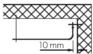
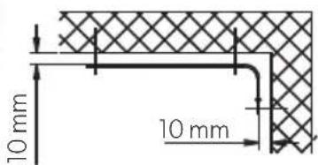
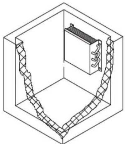
Installing the evaporator
The evaporator must be installed in the cooling container (except CS-NC15, the evaporator is premounted).
Observe the following in the process:
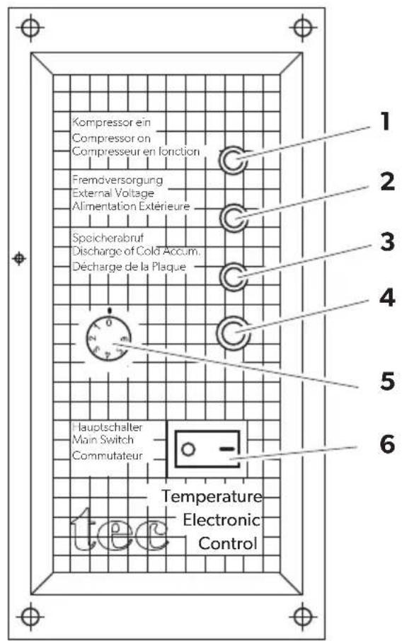
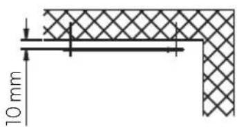
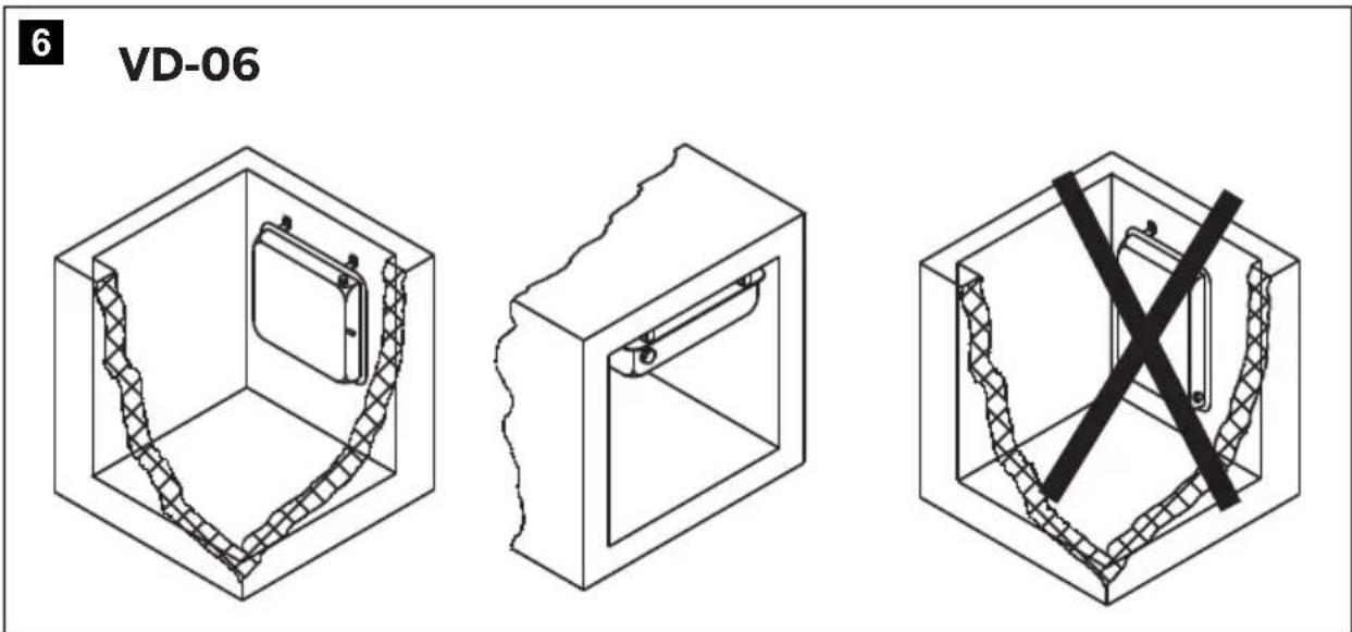
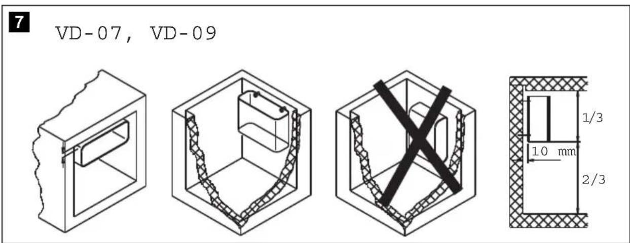
- Correct installation position (fig. 3, page 4 up to fig. 9, page 6)
- Arrangement in the cooling container as far to the top as possible
• Install a least 10 mm from the wall (not VD-14N and VD-15).

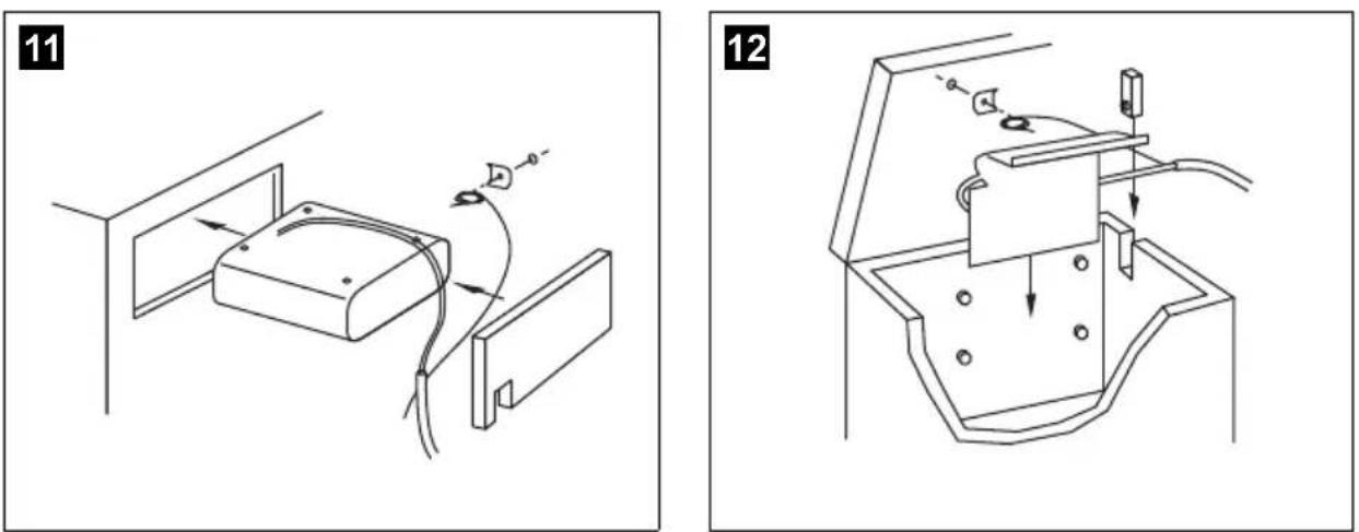
NOTICE!
For cooling units without valve couplings (ready-to install units): Do not open the refrigerant circuit during installation. You may have to make the wall openings larger to be able to slide the evaporator through them (fig. 11, page 6). Or alternatively, you create an opening that allows you to install the cooling lines at the top (fig. 12, page 6).
Connecting the evaporator
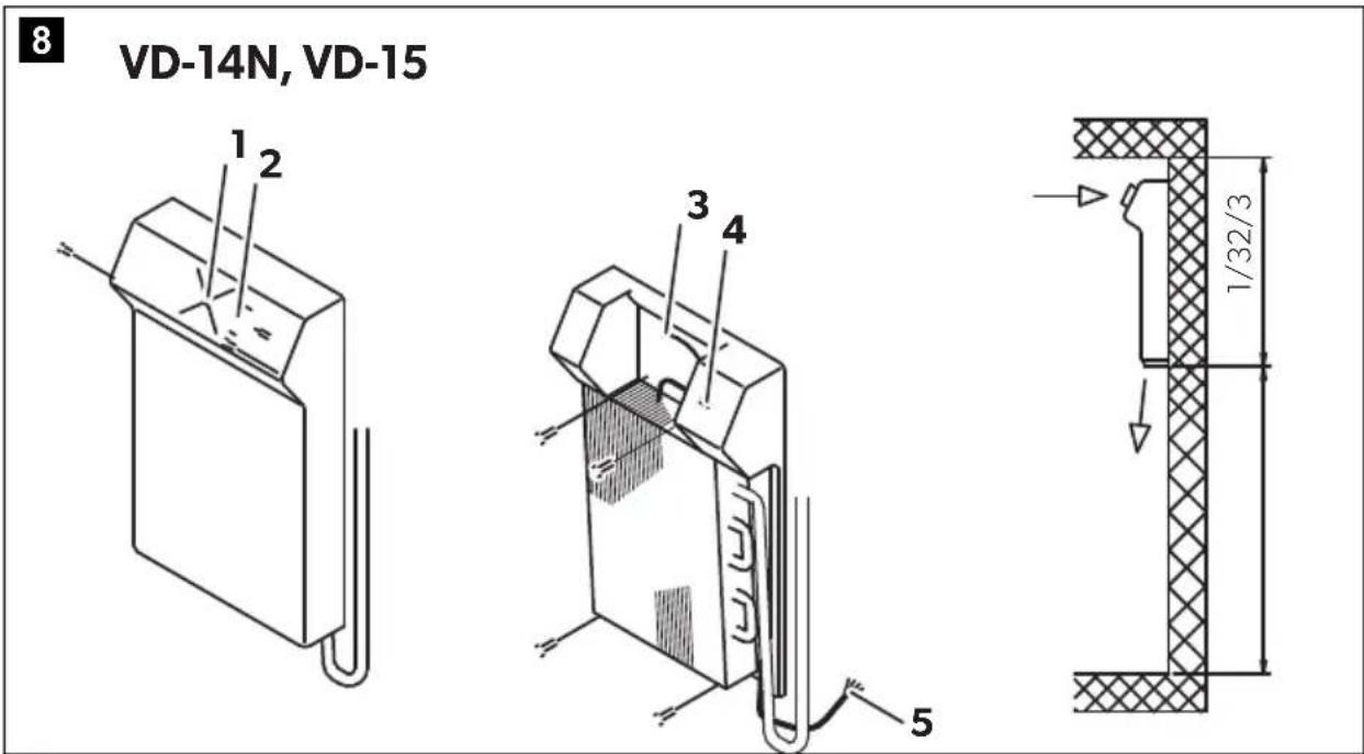
▶ Connect the evaporators VD-14N and VD-15 in accordance with fig. 10, page 6.
▶ Connect evaporator VD-16 according to fig. 9, page 6.
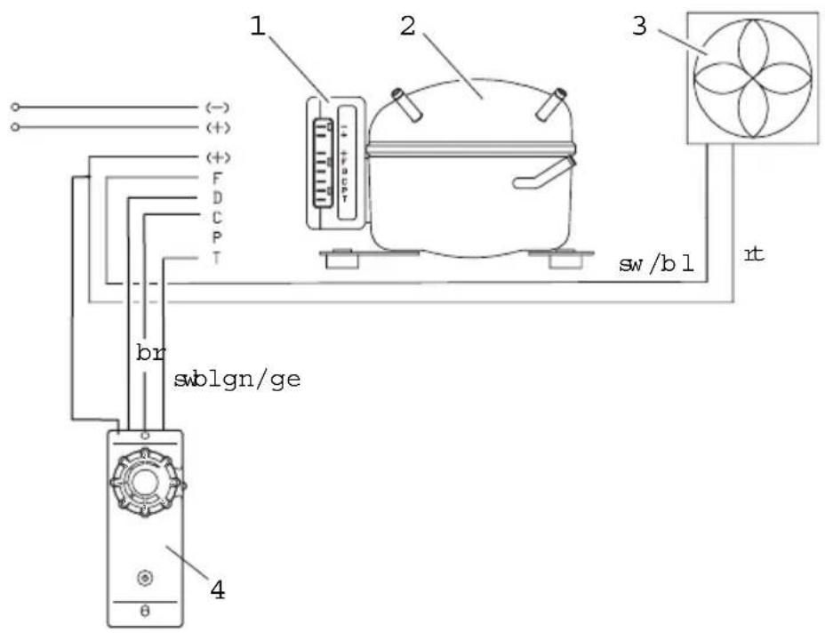
▶ Connect other evaporators according to fig. 19, page 9.
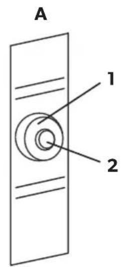
Keys for the illustrations
No. in fig. 8, page 5 Explanation
1 DC fan
2 Thermostat button
3 Connection plug for DC fan
4 Thermostat
5 Connection cable
No. in fig. 9, page 6 Explanation
1 Connection cable
No. in fig. 10, page 6 Explanation
1 Connection cable
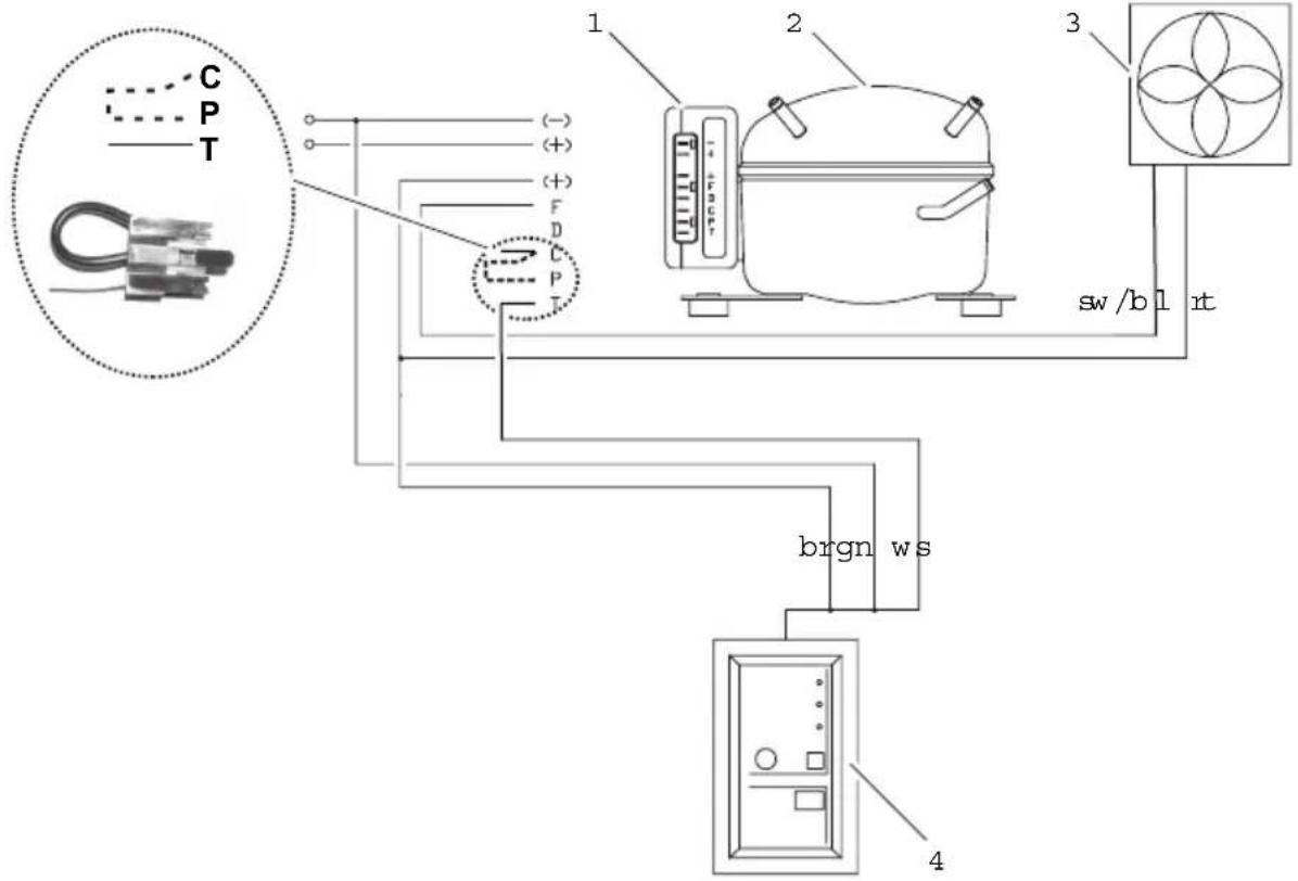
No. in
fig. 19, page 9 and Explanation fig. 20, page 9
1 Connection block
2 Compressor
3 Fan
4 Switch fig. 19 or TEC controller fig. 20

NOTICE!
Carefully insulate and seal off the wall openings after installation to prevent moisture penetration.
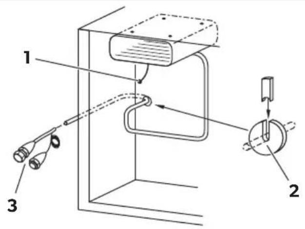
For cooling units with valve couplings
▶ Cut out a hole with a diameter of at least 30 mm (fig. 13, page 7) for the cooling lines. To do this, use a circular cutter.

NOTICE!
Never bend the connecting line between the evaporator and the unit. The minimum bending radius is 25 mm.
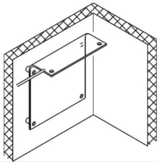
7.3 Installing the cooling unit
It is important to select the proper location for setting up the unit. To ensure trouble-free operation, please note the following points:
- Set up the cooling unit in a dry, sheltered place. Avoid placing it near heat sources such as radiators, gas ovens or hot water pipes. Do not place in direct sunlight.
- On a boat, install the cooling unit, if possible, below the waterline.
- The refrigeration unit functions at a tilt angle of up to 30^ . Install the unit on a flat base so that it will still operate, even at the strongest possible inclination.
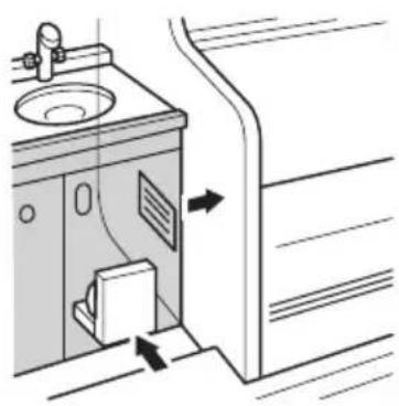
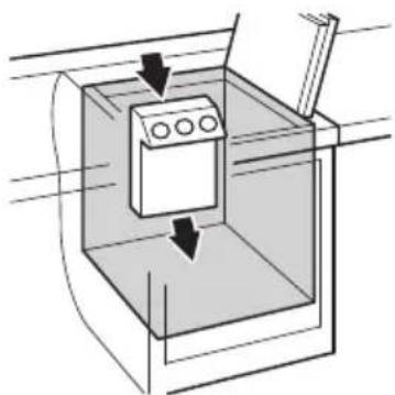
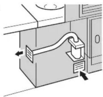
• The heated air must dissipate unhindered (fig. 14, page 7).
- When installing the cooling unit in a closed room such as a wardrobe, pantry or aft compartment, openings must have a cross section of at least 200cm^2 (25cm×8cm) for cooling and exhaust air.
• Make sure that the air flow on the condenser (fig. 14 C, page 7) is not restricted.
- Maintain a minimum distance between the condenser and adjoining wall of 50 mm.
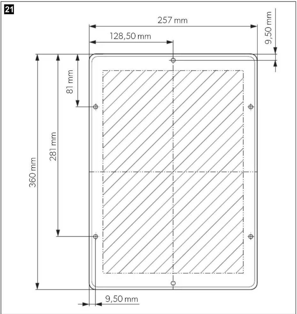
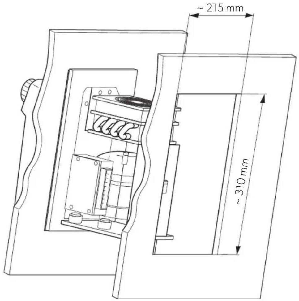
- CS-NC15: Observe the drilling template (fig. 21, page 11) and the installation drawing (fig. 22, page 12).
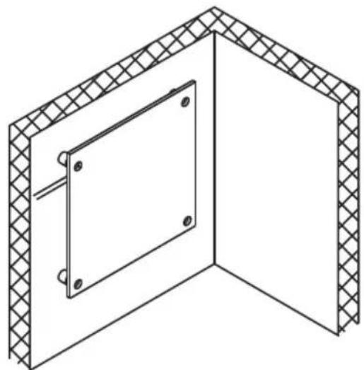
7.4 Installing the external temperature regulator
Mechanical thermostat
The temperature regulator can be mounted either on the outside or inside of the cooling container. The interior temperature is regulated depending on the surface temperature of the evaporator, or for VD-14N and VD-15, depending on the room temperature.
▶ Connect the coiled end of the sensor cable to the evaporator (fig. 15, page 8, not VD-14N, VD-15) using the clamping plate. This is premounted on VD-14N, VD-15.
▶ Make sure that the sensor line does not make contact anywhere else with the evaporator or with the suction line.
TEC control
The TEC control must be attached outside of the cooling container. The internal temperature is regulated according to the evaporator surface temperature.
The temperature sensor has been factory-mounted to the accumulator.
▶ Connect the temperature sensor with the TEC control via the plug-in coupling.
Mount the one-way couplings (not CS-NC15)

NOTICE!
Only persons who are skilled and knowledgeable in the field of refrigeration technology may connect one-way couplings. The general regulations for handling refrigerants must be observed!
The one-way couplings are only suitable for connecting the refrigeration units once. Re-opening or improper connection of the couplings will result in a complete loss of the refrigerant and in the failure of the refrigeration unit!
In such cases, the two previously connected parts of the cooling unit must be disassembled and send in. At the factory, the one-way couplings are renewed and the product is refilled with refrigerant.
The two components of the refrigeration unit – the evaporator and the compressor-condenser unit – are supplied separately. The components are connected with one-way couplings. The refrigerant quantity required to operate the entire refrigeration unit is already contained in the two components. A subsequent filling with refrigerant is, therefore, not necessary.
▶ Assemble the compressor-condenser unit and the evaporator unit.
Remove the protective caps and plugs from the unconnected halves of the one-way coupling of the compressor-condenser unit and the evaporator unit.
▶ Carefully clean the coupling seat and the threaded surface to prevent dirt or foreign material from entering the system.

NOTICE! Risk of coolant leakage
• Always use two wrenches when tightening the one-way couplings to prevent the pipes from twisting!
- Reusing the one-way couplings is not permitted!
- Determine which of the two one-way clutch connections is more difficult to access with the wrench and connect it first.
- Always connect only one one-way coupling connection and then the second.

NOTE
The O-ring is only an interim seal during the initial connection of the one-way couplings. This O-ring is only used for the initial sealing between the piercing of the diaphragm and the final metallic sealing. A leak-free seal is only achieved by a metallic connection between the two coupling halves.
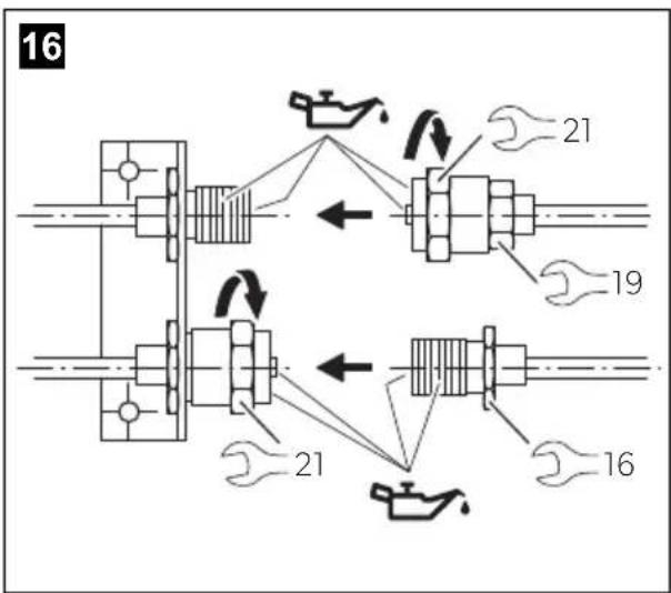
▶ Apply refrigerant oil to the internal and external threads and to the internal mandrels (fig. 16, page 8).
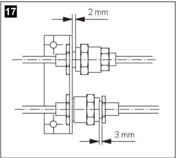
▶ Connect the two halves of the coupling and screw them together by hand at first (fig. 17, page 8). Do not use a wrench!
One-way coupling with union nut:
▶ Screw on the coupling half with the union nut using a wrench size 21 mm and a wrench size 19 mm up to the end of the thread or until a noticeable resistance is felt. Do not tighten the screw connection yet.
The wrench size 19 mm serves as a guide when screwing on the union nut.
Connection of the one-way coupling with external thread:
▶ Screw on the coupling half with the union nut using a wrench size 21 mm and a wrench size 16 mm up to the end of the thread or until a noticeable resistance is felt. Do not tighten the screw connection yet.
The wrench size 16 mm is used for counterholding when screwing on the union nut.
▶ Use a pencil to draw a line lengthwise from the union nut to the bracket of the opposite coupling half.
Now tighten the union nut firmly with a torque of 30 Nm or another 1/4 turn. The offset of the line shows how strongly the one-way coupling was tightened.
This last turn is necessary to ensure a leak-free connection between the coupling halves.

NOTE
The distance between the beginning of the union nut and the hexagon of the external thread must not exceed 3 mm (fig. 17, page 8).
▶ Perform a leak test on the coupling connections. This ensures that the one-way couplings are correctly connected and the sealing is functional.
7.5 Connecting the cooling unit
Connecting to a battery
The cooling unit can be operated from a 12 V or a 24 V DC voltage supply.

NOTICE!
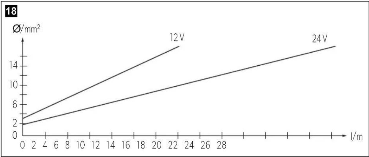
To avoid voltage loss and therefore a drop in performance, the cable should be kept as short as possible and should not be interrupted. For this reason avoid additional switches, plugs or power strips.
▶ Determine the required cross section of the cable in relation to the cable length according to fig. 18, page 8.
Key for fig. 18, page 8
Co-ordinate axis Meaning Unit
| Cable length m
∅Cable cross section mm²

NOTICE!
Make sure that the polarity is correct.
▶ Before you start up the unit for the first time, check that the operating voltage matches the battery voltage (see type plate).
- Connect your cooling unit
- as directly as possible to the pole of the battery or
- to a plug socket which is fuse protected with at least 15 A (at 12 V) or 7.5 A (at 24 V).

NOTICE!
Disconnect the cooling device and other power consuming devices from the battery before you connect the battery to a quick charging device. Overvoltage can damage the electronics of the device.
For safety reasons the cooling unit is equipped with an electronic system to prevent polarity reversal. This protects the cooling unit when it is connected to a battery.
Connecting to a 230 V mains supply

WARNING!
- Never handle plugs and switches with wet hands or if you are standing on a wet surface.
- If you are operating your cooling device on board a boat with a mains connection of 230 V from the land, you must install a residual current circuit breaker between the 230 V mains supply and the cooling device.
Seek advice from a trained technician.
▶ To operate the cooling unit from the 230 V mains, use the rectifier
- CoolPower EPS100 for devices with BD35F compressor (50/80/CS/CS series),
– CoolPower MPS35 for devices with BD35F compressor (50/80/CS/CS series),
– CoolPower MPS50 for devices with BD50F compressor (90 series).

NOTE
The output voltage of the described rectifier is 24 V. Please remember this when connecting other consumers at a later time.
8 Using the cooling unit
8.1 Energy saving tips
- Choose a well ventilated installation location which is protected from direct sunlight.
- Allow hot food to cool down first before placing it in the device.
- Do not open the refrigerated container more often than necessary.
- Do not leave the door open for longer than necessary.
- Defrost the refrigerated container once a layer of ice forms.
- Avoid unnecessary low temperatures.
- Clean the condenser of dust and dirt at regular intervals.
- Clean the lid seal regularly.
8.2 Start the cooling unit
Devices without TEC control
▶ Switch in the cooling unit by turning the control button clockwise (fig. 1 A1 or B1, page 3).
If you turn the control button further, you can regulate the temperature. Devices with energy storage function offer a storage activation button (fig. 1 A2, page 3).

NOTE
If the red LED flashed or glows, a fault has occurred and the system cannot be operated (see error table in Chapter chapter "LED on the thermal element (fig. 1 2, page 3)" on page 29).
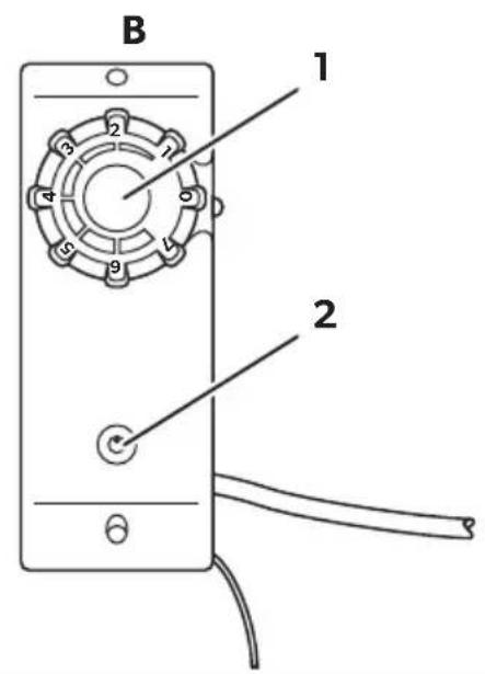
Devices with TEC control
Devices with TEC control are started by actuating the main switch (fig. 2 6, page 3). You can then regulate the temperature (fig. 2 5, page 3) with the temperature selector.
8.3 Shutting down the cooling unit
If you do not intend to use the cooling device for a prolonged period, proceed as follows:
▶ Devices without TEC control: Turn the control to 0.
▶ Devices with TEC control: Switch off the device with the main switch (fig. 2 6, page 3).
▶ Disconnect the power cable from the battery or pull the DC cable plug out of the rectifier.
▶ Clean the cooling device.
Leave the door slightly open over the cover. This prevents odour build-up.
9 Use coolant accumulator
9.1 Display and control elements of devices with TEC program control
No. in
fig. 2,
page 3
Explanation
1 Green LED: Indicates that the compressor is working.
2 Yellow LED: indicates that the external power supply is present (voltage is higher than 13.5 V or 27.0 V).
The LED flashes if the external power supply is too low (voltage ≤ 10.7 V or 21.7 V. Version E: ≤ 10.7 V or 22.0 V).
3 Red LED: indicates that the accumulator is being discharged because
- the discharge button has been pressed
- Low voltage shutdown (voltage ≤ 10.7 V or 21.4 V. Version E: ≤ 10.7 V or 22.0 V).
4 Accumulator discharge button: interrupts compressor operation until
• the stored cold energy is exhausted
- The external supply voltage level is restored after low voltage.
5 Temperature selector: allows the temperature in the cooling area to be set as required
Min. (left limit) = warmest setting
Max. (right limit) = coldest setting
6 Main switch: for switching the cooling device on and off.
Position 0 = OFF
Position - = ON
9.2 Accumulator function
The accumulator function ensures that cold energy is stored automatically (up to 8 hours) if enough electrical power is available, for example when supplied by a mains adapter.
Stored cooling power is discharged
• automatically when the switch-off voltage is reached (see the table on page 18)
• or manually by pressing the discharge button (fig. 1 A2 or fig. 2 4, page 3).

NOTE
The cold accumulator can only be discharged manually if it was fully charged beforehand.
The accumulator is automatically charged if,
• the restart voltage is exceeded
- or the accumulator is empty and you switch the device off and on again using the control button(fig. 2 6, page 3, does only function on VD-06).

NOTICE!
When you are discharging the accumulator, although there is an external supply of power – for example to avoid operating noise from the compressor – use the main switch to switch the unit off (fig. 1 B1 or fig. 2 6, page 3).

NOTE
Please remember: Low internal temperature = high current consumption!
10 Warranty
The statutory warranty period applies. If the product is defective, please contact the manufacturer's branch in your country (see dometic.com/dealer) or your retailer.
For repair and warranty processing, please include the following documents when you send in the device:
• A copy of the receipt with purchasing date
- A reason for the claim or description of the fault
11 Disposal
Place the packaging material in the appropriate recycling waste bins, wherever possible.
If you wish to finally dispose of the product, ask your local recycling center or specialist dealer for details about how to do this in accordance with the applicable disposal regulations.
12 Troubleshooting
LED on the thermal element (fig. 1 2, page 3)
Number of flashes Error type Remedy
| 1 Battery protection shutdown Check battery voltage, fuse and cable cross section | |
| 2 Fan overvoltage shutdown Check condenser and evaporator fan current: total target value < 0.5 A | |
| 3 Compressor start-up fault Reduce load on cooling system: | · Ensure good ventilation around the cooling unit · Store pre-cooled goods |
| 4 Compressor overload shutdown Reduce load on cooling system: | · Ensure good ventilation around the cooling unit · Store pre-cooled goods |
| 5 Electronic fuse shutdown Reduce load on cooling system: | · Ensure good ventilation around the cooling unit |
Compressor does not run
Fault Possible cause Remedy
| U_T=0V | The connection between the battery and the - electronics is interrupted | Establish a connection |
| Main switch defective (if installed) | Replace the main switch | |
| Additional supply line fuse has blown (if installed) | Replace the fuse | |
| U_T≤ U_ON | Battery voltage is too low | Charge the battery |
| Start attempt with U_T≤ U_OFF | Loose cablesPoor contact (corrosion) | Establish a connection |
| Battery capacity too low | Replace the battery | |
| Cable cross section too low | Replace the cable (fig. 18, page 8) |
Fault Possible cause Remedy
| Start attempt with U_T ≥ U_ON | Ambient temperature too high – |
| Insufficient ventilation and/or cooling Provide improved ventilation for the cooling unit | |
| Condenser is dirty Clean the condenser | |
| Fan defective (if installed) Replace the fan |
U_T Voltage between the positive and negative electronic terminals
U_ON Switch-on voltage of the electronics
U_OFF Switch-off voltage of the electronics
Interior temperature too low in control setting 1
Fault Possible cause Remedy
| Compressor runs constantly | Thermostat sensor has no contact on the evaporator | Secure the sensor |
| Thermostat defective Change the thermostat | ||
| Compressor runs for a long time | Large quantities have been frozen in the freezer compartment | - |
Cooling capacity drops, interior temperature rises
Fault Possible cause Remedy
| Compressor runs for a long time/continuously | Evaporator is iced over Defrost the evaporator |
| Ambient temperature too high – | |
| Insufficient ventilation and/or cooling Provide improved ventilation for the cooling unit | |
| Condenser is dirty Clean the condenser | |
| Fan defective (if installed) Replace the fan | |
| Compressor runs infrequently | Battery capacity exhausted Charge the battery |
Unusual noises
Fault Possible cause Remedy
| Loud humming A component of the refrigerant circuit can-not move freely (lies against the wall) | Bend the component carefully away from the obstruction |
| Foreign body jammed between the cooling device and the wall | Remove the foreign body |
| Fan noise (if installed) Clean the fan blades |
13 Technical data
| 50 54 55 | |||
| Max. cooling area contents: | 80 litres 130 litres | ||
| Connection voltage: | 12 V--- or 24 V--- | ||
| Power consumption: 35 | -40 W, depending on the evaporator type | ||
| Coolant quantity: 28 g 35 g | |||
| CO2 equivalent: 0.040 t 0.050 t | |||
| Global warming potential (GWP): | 1430 | ||
| Dimensions (W x H x D) in mm: | 315 x 140 x 170 | 386x155x130 | 220x160x220 |
| Weight: | 3.74 kg 6.0 kg | 6.5 kg | |
| 84 | 85 | 86 | |
| Max. cooling area contents: | 250 litres | ||
| Connection voltage: | 12 V--- or 24 V--- | ||
| Coolant quantity: | 45 g | ||
| CO2 equivalent: | 0.064 t | ||
| Global warming potential (GWP): | 1430 | ||
| Dimensions (W x H x D) in mm: | 386x155x130 | 220x155x220 | 220x230x177 |
| Weight: | 6.0 kg94 95 96 | 6.0 kg | 6.5 kg |
| Max. cooling area contents: | 400 litres | ||
| Connection voltage: | 12 V--- or 24 V--- | ||
| Coolant quantity: 60 g | |||
| CO2 equivalent: 0.086 t | |||
| Global warming potential (GWP): | 1430 | ||
| Dimensions (W x H x D) in mm: | 386x155x130 220x155x220 220x230x177 | ||
| Weight: 6.0 kg 6.0 kg 6.5 kg | |||
| CS-NC15 | |
| Max. cooling area contents: | 250 litres |
| Connection voltage: | 12 V--- or 24 V--- |
| Coolant quantity: 60 g | |
| CO2 equivalent: 0.086 t | |
| Global warming potential (GWP): | 1430 |
| Dimensions (W x H x D) in mm: | 360x255x275 |
| Weight: 8.5 kg |
| VD-01 VD-02 VD-03 VD-04 | ||||
| Max. cooling area content at 35 mm PU insulation: | 80 litres 30 litres | 170 litres | 130 litres | |
| Max. cooling area content at 50 mm PU insulation: | 100 litres | 50 litres | 200 litres | 170 litres |
| Power consumption: | 35 W | 35 W | 50 W | 45 W |
| Voltage | 12 V--- or 24 V--- | |||
| Coolant quantity: | 17 g | 20 g | 30 g | |
| CO2 equivalent: | 0.024 t 0.029 t | 0.043 t | ||
| Global warming potential (GWP): | 1430 | |||
| Dimensions (W x H x D) in mm: | 300x245x110 275x215x25 380x230x82 375x255x100 | |||
| Weight: 1.5 kg 1.0 kg 2 | 0 kg 1.5 kg | |||
| CU-50 + VD-01 | CU-50 + VD-02 | CU-50 + VD-07 | ||
| Max. cooling area content at 35 mm PU insulation: | 50 litres 30 litres 60 litres | |||
| Max. cooling area content at 50 mm PU insulation: | 75 litres 50 litres 80 litres | |||
| Power consumption: 30 W | ||||
| Temperature: ambient: 32 °C, internal: 5 °C | ||||
| VD-05 VD-07 VD-08 VD-09 | ||||
| Max. cooling area content at 35 mm PU insulation: | 130 litres 100 litres 160 litres 160 litres | |||
| Max. cooling area content at 50 mm PU insulation: | 170 litres 130 litres 180 litres 180 litres | |||
| Power consumption: | 45 W | 35 W | 60 W | 60 W |
| Voltage | 12 V--- or 24 V--- | |||
| Coolant quantity: | 30 g | 45 g | 15 g | 65 g |
| CO2 equivalent: | 0.043 t | 0.064 t | 0.021 t | 0.093 t |
| Global warming potential (GWP): | 1430 | |||
| Dimensions (W x H x D) in mm: | 375x350x25 | 255x210x90 | 450x270x340 | 365x140x270 |
| Weight: 1.5 kg 1.5 kg 2 | 0 kg 2 | 0 kg | ||
| VD-14N VD-15 VD-18 | |||
| Max. cooling area content at 35 mm PU insulation: | 300 litres 200 | litres 100 litres | |
| Max. cooling area content at 50 mm PU insulation: | 400 litres 250 | litres 150 litres | |
| Power consumption: 80 W 60 W 45 W | |||
| Voltage | 12 V--- or 24 V--- | ||
| Coolant quantity: 15 g | |||
| CO2 equivalent: 0.021 t | |||
| Global warming potential (GWP): | 1430 | ||
| Dimensions(W x H x D) in mm: | 220x275x65 220x275x65 350x250x25 | ||
| Weight: 2.5 kg 1.5 kg 1.5 kg | |||
| VD-16 VD-21 | ||
| Max. cooling area content at 60 mm PU insulation: | 130 litres | 250 litres |
| Max. cooling area content at 100 mm PU insulation: | 200 litres | 300 litres |
| Power consumption: | 60 W | 60 W |
| Voltage | 12 V--- or 24 V--- | |
| Coolant quantity: | 40 g | 10 g |
| CO2 equivalent: | 0.057 t | 0.014 t |
| Global warming potential (GWP): | 1430 | |
| Dimensions (W x H x D) in mm: | 330x260x130 | 1370x305x10 |
| Weight: | 2.5 kg 4.0 kg | |
| VD-16 for series 80 VD-16 for series 90 | ||
| Max. cooling area content at 35 mm PU insulation: | 120 litres 200 litres | |
| Max. cooling area content at 50 mm PU insulation: | 200 litres 250 litres | |
| Power consumption: 65 | W 80 W | |
| Voltage | 12 V--- or 24 V--- | |
| Coolant quantity: 40 g | ||
| CO2 equivalent: 0.057 t | ||
| Global warming potential (GWP): | 1430 | |
| Dimensions (W x H x D) in mm: | 380x300x62 | |
| Weight: 5.0 kg | ||
Test/certificates:
The coolant circuit contains R-134a.
Contains fluorinated greenhouse gases
6 Description technique 64
6 Description technique
3 Rød LED: Viser, at akkumulatoren aflades, fordi
| Tilkoblingsspenning Utkoblingsspenning | Gjeninnkoblingsspenning | |
| 12 V | 10,7 V 13,0 V | |
| 24 V | 22,0 V 26,0 V | |
| 12 V | 10,7 V 13,0 V |
| 24 V | 22,0 V 26,0 V |
dometic.com/sales-offices