P3340 - Fan RYOBI - Free user manual and instructions
Find the device manual for free P3340 RYOBI in PDF.

| Brand | RYOBI |
| Model | P3340 |
| Product Type | Hybrid Portable Fan |
| Power (Alternating Current) | 120 V AC, 60 Hz |
| Power (Direct Current) | 18 V DC via ONE+ battery pack (not included) |
| Speeds | 3 speeds (low, medium, high) + off |
| Switch | 4-position rotary |
| Power cord | 1.2 m (4 ft), included |
| Weight | Approximately 2.3 kg (estimated) |
| Dimensions (height) | Approximately 50 cm (estimated) |
| Head diameter | 457.2 mm (18 in) |
| Construction type | Double insulation (Class II) |
| Head angle | Adjustable (loosening knobs) |
| Wall mount | Possible via keyhole bracket (screw not included) |
| Recommended use | General indoor ventilation |
| Moisture protection | Do not expose to rain or moisture |
| Maintenance | Clean with dry cloth, no solvents |
| Warranty | 3 years (limited) |
| Customer service | 1-800-525-2579 (United States) |
| Replacement parts | Contact customer service or authorized service center |
Frequently Asked Questions - P3340 RYOBI
User questions about P3340 RYOBI
0 question about this device. Answer the ones you know or ask your own.
Ask a new question about this device
Download the instructions for your Fan in PDF format for free! Find your manual P3340 - RYOBI and take your electronic device back in hand. On this page are published all the documents necessary for the use of your device. P3340 by RYOBI.
USER MANUAL P3340 RYOBI
natural_image
Line drawing of a mechanical fan with visible blades and mounting base (no text or symbols)INCLUDES: Fan Head, Frame, Power Cord, Operator's Manual
TABLE OF CONTENTS
****************************************************************************************
■ Important Safety Instructions......2
■ Portable Fan Safety Warnings......3
■ Electrical....4
■ Symbols....5
■ Features....5
■ Assembly......6
■ Operation....6-7
■ Maintenance....7
■ Illustrations 8-9
■ Parts Ordering / Service ..... Back Page

WARNING: To reduce the of injury, the user must read and understand the operator's manual are using this product.
SAVE THIS MANUAL FOR FUTURE REFERENCE
IMPORTANT SAFETY INSTRUCTIONS

WARNING!
READ AND SAVE THESE INSTRUCTIONS. Failure to follow all instructions listed below, may result in electric shock, fire and/or serious personal injury.
SAVE THESE INSTRUCTIONS
WORK AREA
- Keep your work area clean and well lit. Cluttered benches and dark areas invite accidents.
■ Do not operate battery products in explosive atmospheres, such as in the presence of flammable liquids, gases, or dust. Battery products create sparks which may ignite the dust or fumes.
ELECTRICAL SAFETY
■ Use this product only with batteries and chargers listed in tool/appliance/battery pack/charger correlation supplement 987000-432.
- Do not defeat the safety purpose of the polarized or grounding-type plug. A polarized plug has two blades with one wider than the other. A grounding type plug has two blades and a third grounding prong. The wide blade or the third prong are provided for your safety. If the provided plug does not fit into your outlet, consult an electrician for replacement of the obsolete outlet.
■ Protect the extension cord from being walked on or pinched particularly at plugs, convenience receptacles, and the point where they exit from the product.
■ Unplug this product during lightning storms or when when not in use.
- Check extension cords before each use. If damaged replace immediately. Never use a product with a damaged cord since touching the damaged area could cause electrical shock resulting in serious injury.
PERSONAL SAFETY
■ Dress properly. Do not wear loose clothing or jewelry. Contain long hair. Keep your hair, clothing, and gloves away from moving parts. Loose clothes, jewelry, or long hair can be caught in moving parts or drawn into air vents.
■ Prevent unintentional starting. Ensure the switch is in the off-position before connecting to power source and/or battery pack, picking up or carrying the product. Carrying battery packs with your finger on the switch or energizing products that have the switch on invites accidents.
■ Do not overreach. Keep proper footing and balance at all times. Proper footing and balance enable better control of the product in unexpected situations.
■ Do not use on a ladder or unstable support. Stable footing on a solid surface enables better control of the product in unexpected situations.
■ Constantly stay aware of cord location.
BATTERY PRODUCT USE AND CARE
- Do not use the product if switch does not turn it on or off. A battery tool that cannot be controlled with the switch is dangerous and must be repaired.
■ Disconnect battery pack or extension cord from product or place the switch in the locked or off position before making any adjustments, changing accessories, or storing the product. Such preventive safety measures reduce the risk of starting the product accidentally.
■ Recharge only with the charger specified by the manufacturer. A charger that is suitable for one type of battery pack may create a risk of fire when used with another battery pack.
■ Use battery products only with specifically designated battery packs. Use of any other battery packs may create a risk of injury and fire.
■ When battery pack is not in use, keep it away from other metal objects, like paper clips, coins, keys, nails, screws or other small metal objects, that can make a connection from one terminal to another. Shorting the battery terminals together may cause burns or a fire.
■ Under abusive conditions, liquid may be ejected from the battery; avoid contact. If contact accidentally occurs, flush with water. If liquid contacts eyes, additionally seek medical help. Liquid ejected from the battery may cause irritation or burns. - Do not use a battery pack or tool that is damaged or modified. Damaged or modified batteries may exhibit unpredictable behavior resulting in fire, explosion, or risk of injury.
- Do not expose a battery pack or tool to fire or excessive temperature. Exposure to fire or temperature above 265° F may cause explosion.
■ Follow all charging instructions and do not charge the battery pack or tool outside the temperature range specified in the instructions. Charging improperly or at temperatures outside the specified range may damage the battery and increase the risk of fire.
SERVICE
■ Have your power tool serviced by a qualified repair person using only identical replacement parts. This will ensure that the safety of the power tool is maintained.
■ Never service damaged battery packs. Service of battery packs should only be performed by the manufacturer or authorized service providers.
PORTABLE FAN SAFETY WARNINGS
- Know your portable fan. Read operator's manual carefully. Learn its applications and limitations, as well as the specific potential hazards related to this product. Following this rule will reduce the risk of electric shock, fire, or serious injury.
■ To reduce the risk of electric shock, do not use this fan near water, especially when it is powered by the power cord.
■ Clean only with dry cloth.
■ Do not operate near any heat sources such as radiators, heat registers, stoves, or other apparatus (including amplifiers) that produce heat.
■ Battery products do not have to be plugged into an electrical outlet; therefore, they are always in operating condition. Be aware of possible hazards when not using your battery product or when changing accessories. Following this rule will reduce the risk of electric shock, fire, or serious personal injury. - Do not place battery tools or their batteries near fire or heat. This will reduce the risk of explosion and possibly injury.
-
Do not crush, drop or damage battery pack. Do not use a battery pack or charger that has been dropped or received a sharp blow. A damaged battery is subject to explosion. Properly dispose of a dropped or damaged battery immediately.
■ Batteries can explode in the presence of a source of ignition, such as a pilot light. To reduce the risk of serious personal injury, never use any cordless product in the presence of open flame. An exploded battery can propel debris and chemicals. If exposed, flush with water immediately. -
Do not charge battery tool in a damp or wet location. Do not use, store, or charge battery packs or products in locations where the temperature is less than 50°F or more than 100°F. Do not store outside or in vehicles.
■ Under extreme usage or temperature conditions, battery leakage may occur. If liquid comes in contact with your skin, wash immediately with soap and water. If liquid gets into your eyes, flush them with clean water for at least 10 minutes, then seek immediate medical attention. Following this rule will reduce the risk of serious personal injury.
■ To reduce the risk of fire or electric shock, do not use this portable fan with any solid-state speed control device.
■ Not for use in kitchens.
■ For general ventilating use only. Do not use to exhaust hazardous or explosive materials and vapors.
■ To reduce the risk of personal injury and electric shock, the portable fan should not be played with or placed where small children can reach it.
■ To reduce the risk of electric shock, do not expose to water or rain. Do not allow the battery pack to get wet.
■ Save these instructions. Refer to them frequently and use them to instruct others who may use this tool. If you loan someone this tool, loan them these instructions also.
ELECTRICAL
DOUBLE INSULATION
Double insulation is a concept in safety in electric products, which eliminates the need for the usual three-wire grounded power cord. All exposed metal parts are isolated from the internal metal motor components with protecting insulation. Double insulated products do not need to be grounded.

WARNING:
The double insulated system is intended to protect the user from shock resulting from a break in the product's internal wiring. Observe all normal safety precautions to avoid electrical shock.
NOTE: Servicing of a product with double insulation requires extreme care and knowledge of the system and should be performed only by a qualified service technician. For service, we suggest you return the product to your nearest authorized service center for repair. Always use original factory replacement parts when servicing.
ELECTRICAL CONNECTION
This is a hybrid product capable of operating on alternating current (AC) through an extension cord or direct current (DC) through a battery pack. If the product does not operate when an extension cord or battery pack is installed, double-check the power supply.
■ To use alternating current, connect the product to a power supply that is 120 volts, AC only (normal household current), 60 Hz.
■ To use direct current, install a manufacturer-recommended 18 volt battery pack only.
EXTENSION CORDS
When using a product at a considerable distance from a power source, be sure to use an extension cord that has the capacity to handle the current the product will draw. An undersized cord will cause a drop in line voltage, resulting in overheating and loss of power. Use the chart to determine the minimum wire size required in an extension cord. Only round jacketed cords listed by Underwriter's Laboratories (UL) should be used.
When using this product outdoors, use an extension cord that is designed for outside use. This type of cord is designated with "WA" or "W" on the cord's jacket.
Before using any extension cord, inspect it for loose or exposed wires and cut or worn insulation.
**Ampere rating (on product data plate)
0-2.0 2.1-3.4 3.5-5.0 5.1-7.0 7.1-12.0 12.1-16.0
| Cord Length | Wire Size (A.W.G.) | |||||
| 25' | 16 | 16 | 16 | 16 | 14 | 14 |
| 50' | 16 | 16 | 16 | 14 | 14 | 12 |
| 100' | 16 | 16 | 14 | 12 | 10 | — |
**Used on 12 gauge - 20 amp circuit
NOTE: AWG = American Wire Gauge

WARNING:
Keep the extension cord clear of the working area. Position the cord so that it will not get caught on lumber, tools, or other obstructions while you are working with this product. Failure to do so can result in serious personal injury.

WARNING:
Check extension cords before each use. If damaged replace immediately. Never use a product with a damaged cord since touching the damaged area could cause electrical shock resulting in serious injury.
SYMBOLS
| The following signal words and meanings are intended to explain the levels of risk associated with this product. | ||
| SYMBOL | SIGNAL | MEANING |
 | DANGER: | Indicates a hazardous situation, which, if not avoided, will result in death or serious injury. |
 | WARNING: | Indicates a hazardous situation, which, if not avoided, could result in death or serious injury. |
 | CAUTION: | Indicates a hazardous situation, that, if not avoided, may result in minor or moderate injury. |
| NOTICE: | (Without Safety Alert Symbol) Indicates information considered important, but not related to a potential injury (e.g. messages relating to property damage). | |
| Some of the following symbols may be used on this product. Please study them and learn their meaning. Proper interpretation of these symbols will allow you to operate the product better and safer. SYMBOL NAME DESIGNATION/EXPLANATION | |||
 | Safety Alert Indicates | a potential personal injury hazard. | |
 | Read Operator's Manual | To reduce the risk of injury, user must read and understand operator's manual before using this product. | |
 | Wet Conditions Alert | Do not expose to rain or use in damp locations. | |
 | Recycle Symbol | This product uses lithium-ion (Li-ion) batteries. Local, state or federal laws may prohibit disposal of batteries in ordinary trash. Consult your local waste authority for information regarding available recycling and/or disposal options. | |
| V Volts Voltage | |||
| A Amperes Current | |||
| Hz Hertz Frequency (cycles per second) | |||
| W Watt Power | |||
| min Minutes Time | |||
| == | Direct Current Type or a characteristic of current | ||
| ~ | Alternating Current Type of current | ||
| ☐ | Class II Tool | Double-insulated construction | |
FEATURES
PRODUCT SPECIFICATIONS
Motor....18 Volt DC
Switch....3 Speed
120 V, AC only, 60 Hz
Power Cord (included)....4 ft.
ASSEMBLY
UNPACKING
This product requires assembly.
- Carefully remove the tool and any accessories from the box. All items listed in the Includes section must be included at the time of purchase.

WARNING:
Items in this Assembly section are not assembled to the product by the manufacturer and require customer installation. Use of a product that may have been improperly assembled could result in serious personal injury.
■ If any parts are damaged or missing, please call 1-800-525-2579 for assistance.

WARNING:
If any parts are damaged or missing do not operate this product until the parts are replaced. Use of this product with damaged or missing parts could result in serious personal injury.

WARNING:
Do not attempt to modify this product or create accessories or attachments not recommended for use with this product. Any such alteration or modification is misuse and could result in a hazardous condition leading to possible serious personal injury.
INSTALLING THE FAN HEAD ONTO THE FRAME
See Figure 1, page 8.
NOTE: Do not operate the fan or connect the power cord or battery pack without first installing the fan head onto the frame.
■ Align the upper tubes on the fan head with the lower tubes on the frame as shown. The spring-loaded locking pins should be aligned with the holes in the lower tube.
■ Push the fan head and frame together until the locking pins click into place in the holes.
OPERATION

WARNING:
Do not allow familiarity with tools to make you careless. Remember that a careless fraction of a second is sufficient to inflict serious injury.

WARNING:
Do not use any attachments or accessories not recommended by the manufacturer of this tool. The use of attachments or accessories not recommended can result in serious personal injury.

WARNING:
Always remove battery pack or unplug extension cord from your product when you are assembling parts, making adjustments, cleaning, or when not in use. Removing battery pack or unplugging extension cord will prevent accidental starting that could cause serious personal injury.
APPLICATIONS
You may use this tool for the purpose listed below:
■ General ventilation of most household spaces

WARNING:
Hybrid tools are always in operating condition. Therefore, switch should always be in the OFF (0) position when not in use.
NOTICE:
This product is designed to be powered by either a RYOBI™ ONE+™ 18V battery pack (DC mode) or by electric power (AC mode). Either power source can be used by installing an approved battery pack or power cord into the product as described in this manual.
INSTALLING/REMOVING BATTERY PACK
See Figure 2, page 9.
■ Place the speed switch in the OFF (0) position.
■ Insert the battery pack into the product as shown.
■ Make sure the latches on each side of the battery pack snap into place and the battery pack is secured before beginning operation.
■ Depress the latches to remove the battery pack.
For complete charging instructions, see the operator's manuals for your battery pack and charger.
OPERATION
NOTE: Use the included power cord only with the RYOBI™ P3340 Fan.
■ Place the speed switch in the OFF (0) position.
■ Insert the female end of the power cord into the product as shown.
■ Connect the male end of the power cord to the power source.
■ Make sure the power cord is secured before beginning operation.
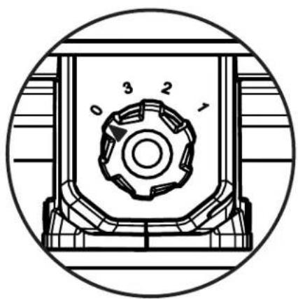
STARTING/STOPPING THE PORTABLE FAN
See Figure 4, page 9.
■ Connect the fan to an AC or DC power supply.
■ To start the fan, turn the speed switch clockwise and select the desired speed.
■ The speed switch has four settings:
0 - Off
3 - High
2 - Medium
1 - Low
■ To stop the fan, turn the speed switch counterclockwise to the OFF (0) position.
HANGING THE PORTABLE FAN WITH THE KEYHOLE MOUNT
See Figure 5, page 9.
NOTE: Be careful not to hang the fan in such a way that it prevents normal fan operation or damages the cord.
■ Use a #9 x 2 in. minimum screw size for mounting the fan.
■ Ensure that the screw is securely fastened into a stud and that the screw is exposed no more than 5/8 in.
■ Slide the keyhole hanger, located on the frame cross member, over the screw. Make sure the fan is securely mounted.
ADJUSTABLE HEAD
See Figure 5, page 9.
To change the angle of the fan head, loosen the adjustment knob on each side of the fan head. Select the desired position and tighten each knob to secure.
NOTICE:
Adjusting the fan head without loosening the adjustment knobs could result in damage to the fan.
MAINTENANCE

WARNING:
When servicing, use only identical replacement parts. Use of any other part could create a hazard or cause product damage.
GENERAL MAINTENANCE
Avoid using solvents when cleaning plastic parts. Most plastics are susceptible to damage from various types of commercial solvents and can be damaged by their use. Use clean cloths to remove dirt, dust, oil, grease, etc.
NOTE: ILLUSTRATIONS START ON PAGE 8 AFTER FRENCH AND SPANISH LANGUAGE SECTIONS.
INSTRUCTIONS IMPORTANTES CONCERNANT LA SÉCURITÉ

AVERTISSEMENT!
Fig. 1
Fig. 2 Fig. 3
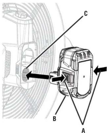
A - Latches (loquets, pestillos)
B - Battery pack (bloc-piles, baterías)
C - Battery port (logements de bloc-piles, puertos de baterías)
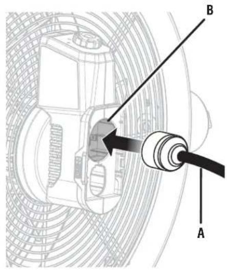
A - Power cord (cordon d'alimentation, cordón de corriente)
B - AC Receptacle (prise, receptáculo)
Fig. 4
To request service, purchase replacement parts, locate an Authorized Service Center and obtain Customer or Technical Support:
Visit www.ryobitools.com or call 1-800-525-2579
If any parts or accessories are damaged or missing, do not return this product to the store. Call 1-800-525-2579 for immediate service.
Please obtain your model and serial number from the product data plate. This product is covered under a 3-year limited Warranty. Proof of purchase is required.
MODEL NUMBER ____ SERIAL NUMBER ____
RYOBI is a trademark of Ryobi Limited and is used pursuant to a license granted by Ryobi Limited.