
P4002 - Electric drain unblocker RYOBI - Free user manual and instructions
Find the device manual for free P4002 RYOBI in PDF.

| Product Type | Electric Drain Cleaner (Pipe Auger) |
| Brand | RYOBI |
| Model | P4002 |
| Cable Diameter | 6.35 mm (0.25 in) |
| Cable Length | 7.62 m (25 ft) |
| Power Supply (AC) | 120 V AC, 60 Hz |
| Power Supply (Battery) | 18 V DC (ONE+ compatible lithium-ion battery) |
| Minimum Pipe Diameter | 19.1 mm (0.75 in) |
| Maximum Pipe Diameter | 50.8 mm (2 in) |
| Applications | Clearing sinks and bathtubs |
| Operating Modes | Feed (F), neutral (N), retract (R); forward/reverse rotation |
| Variable Speed Trigger | Yes, variable pressure to control speed |
| Feed Direction Selector Collar | Allows selection of feed, neutral, or retract |
| Rotation Direction Selector | F/R (feed/retract) and N (neutral) with center lock |
| Safety | Trigger lock, stop in center position, eye protection recommended |
| Maintenance | Clean cable and drain drum after each use |
| Included Accessories | Standard bulb tip, external power cord |
| Replacement Parts Available | Replacement drum, auger tips (bulb, grease, spatula, side) |
| Warranty | Limited 3-year warranty (proof of purchase required) |
Frequently Asked Questions - P4002 RYOBI
User questions about P4002 RYOBI
0 question about this device. Answer the ones you know or ask your own.
Ask a new question about this device
Download the instructions for your Electric drain unblocker in PDF format for free! Find your manual P4002 - RYOBI and take your electronic device back in hand. On this page are published all the documents necessary for the use of your device. P4002 by RYOBI.
USER MANUAL P4002 RYOBI
natural_image
Technical line drawing of a mechanical device with gears and housing (no text or symbols)INCLUDES: Hybrid Drain Auger, Auger Tip, External Power Supply and Operator's Manual
TABLE OF CONTENTS
**********************************************************************
■ General Power Tool
Safety Warnings....2-3
■ Drain Auger Safety Warnings .....4
■ Electrical....5
■ Symbols......6-7
■ Features....8
■ Assembly......8
■ Operation....8-12
■ Maintenance....12
■ Illustrations ......13-14
■ Parts Ordering
and Service ....Back page

WARNING: To reduce the
risk of injury, the user must read and understand the operator's manual before using this product.
SAVE THIS MANUAL FOR
FUTURE REFERENCE
Read all safety warnings and all instructions. Failure to follow the warnings and instructions may result in electric shock, fire, and/or serious injury.
Save all warnings and instructions for future reference. The term “power tool” in the warnings refers to your mains-operated (corded) power tool or battery-operated (cordless) power tool.
WORK AREA SAFETY
- Keep work area clean and well lit. Cluttered or dark areas invite accidents.
- Do not operate power tools in explosive atmospheres, such as in the presence of flammable liquids, gases or dust. Power tools create sparks which may ignite the dust or fumes.
- Keep children and bystanders away while operating a power tool. Distractions can cause you to lose control.
ELECTRICAL SAFETY
■ Power tool plugs must match the outlet. Never modify the plug in any way. Do not use any adapter plugs with earthed (grounded) power tools. Unmodified plugs and matching outlets will reduce risk of electric shock.
■ Avoid body contact with earthed or grounded surfaces, such as pipes, radiators, ranges and refrigerators. There is an increased risk of electric shock if your body is earthed or grounded.
■ Do not expose power tools to rain or wet conditions. Water entering a power tool will increase the risk of electric shock.
- Do not abuse the cord. Never use the cord for carrying, pulling or unplugging the power tool. Keep cord away from heat, oil, sharp edges or moving parts. Damaged or entangled cords increase the risk of electric shock.
■ When operating a power tool outdoors, use an extension cord suitable for outdoor use. Use of a cord suitable for outdoor use reduces the risk of electric shock.
If operating a power tool in a damp location is unavoidable, use a ground fault circuit interrupter (GFCI) protected supply. Use of a GFCI reduces the risk of electric shock.
■ Use this product only with batteries and chargers listed in tool/appliance/battery pack/charger correlation supplement 987000-432.
PERSONAL SAFETY
■ Stay alert, watch what you are doing and use common sense when operating a power tool. Do not use a power tool while you are tired or under the influence of drugs, alcohol or medication. A moment of inattention while operating power tools may result in serious personal injury.
■ Use personal protective equipment. Always wear eye protection. Protective equipment such as dust mask, non-skid safety shoes, hard hat, or hearing protection used for appropriate conditions will reduce personal injuries.
■ Prevent unintentional starting. Ensure the switch is in the off-position before connecting to power source and/or battery pack, picking up or carrying the tool. Carrying power tools with your finger on the switch or energising power tools that have the switch on invites accidents.
■ Remove any adjusting key or wrench before turning the power tool on. A wrench or a key left attached to a rotating part of the power tool may result in personal injury.
- Do not overreach. Keep proper footing and balance at all times. This enables better control of the power tool in unexpected situations.
■ Dress properly. Do not wear loose clothing or jewelry. Keep your hair, clothing and gloves away from moving parts. Loose clothes, jewelry or long hair can be caught in moving parts.
If devices are provided for the connection of dust extraction and collection facilities, ensure these are connected and properly used. Use of dust collection can reduce dust-related hazards.
■ Do not let familiarity gained from frequent use of tools allow you to become complacent and ignore tool safety principles. A careless action can cause severe injury within a fraction of a second.
■ Do not wear loose clothing or jewelry. Contain long hair. Loose clothes, jewelry, or long hair can be drawn into air vents.
- Do not use on a ladder or unstable support. Stable footing on a solid surface enables better control of the power tool in unexpected situations.
GENERAL POWER TOOL SAFETY WARNINGS
POWER TOOL USE AND CARE
- Do not force the power tool. Use the correct power tool for your application. The correct power tool will do the job better and safer at the rate for which it was designed.
- Do not use the power tool if the switch does not turn it on and off. Any power tool that cannot be controlled with the switch is dangerous and must be repaired.
■ Disconnect the plug from the power source and/or the battery pack from the power tool before making any adjustments, changing accessories or storing power tools. Such preventive safety measures reduce the risk of starting the power tool accidentally.
■ Store idle power tools out of the reach of children and do not allow persons unfamiliar with the power tool or these instructions to operate the power tool. Power tools are dangerous in the hands of untrained users. - Maintain power tools. Check for misalignment or binding of moving parts, breakage of parts and any other condition that may affect the power tool's operation. If damaged, have the power tool repaired before use. Many accidents are caused by poorly maintained power tools.
- Keep cutting tools sharp and clean. Properly maintained cutting tools with sharp cutting edges are less likely to bind and are easier to control.
■ Use the power tool, accessories and tool bits etc. in accordance with these instructions, taking into account the working conditions and the work to be performed. Use of the power tool for operations different from those intended could result in a hazardous situation. - Keep handles and grasping surfaces dry, clean and free from oil and grease. Slippery handles and grasping surfaces do not allow for safe handling and control of the tool in unexpected situations.
BATTERY TOOL USE AND CARE
■ Recharge only with the charger specified by the manufacturer. A charger that is suitable for one type of battery pack may create a risk of fire when used with another battery pack.
■ Use power tools only with specifically designated battery packs. Use of any other battery packs may create a risk of injury and fire.
■ When battery pack is not in use, keep it away from other metal objects, like paper clips, coins, keys, nails, screws or other small metal objects, that can make a connection from one terminal to another. Shorting the battery terminals together may cause burns or a fire.
■ Under abusive conditions, liquid may be ejected from the battery; avoid contact. If contact accidentally occurs, flush with water. If liquid contacts eyes, additionally seek medical help. Liquid ejected from the battery may cause irritation or burns.
- Do not use a battery pack or tool that is damaged or modified. Damaged or modified batteries may exhibit unpredictable behavior resulting in fire, explosion, or risk of injury.
- Do not expose a battery pack or tool to fire or excessive temperature. Exposure to fire or temperature above 265° F may cause explosion.
■ Follow all charging instructions and do not charge the battery pack or tool outside the temperature range specified in the instructions. Charging improperly or at temperatures outside the specified range may damage the battery and increase the risk of fire.
SERVICE
■ Have your power tool serviced by a qualified repair person using only identical replacement parts. This will ensure that the safety of the power tool is maintained.
■ Never service damaged battery packs. Service of battery packs should only be performed by the manufacturer or authorized service providers.
DRAIN AUGER SAFETY WARNINGS
■ Always wear safety goggles or eye protection with side shields marked to comply with ANSI Z87.1 when assembling parts, operating the tool, or performing maintenance. Following this rule will reduce the risk of serious personal injury.
■ Position the the drain auger within four inches of the drain or inlet being cleared. Operating the tool at greater distances can result in the cable twisting or binding.
■ Avoid running the tool in reverse for extended periods of time as this can damage the cable.
■ Never place your hand near the drum or the cable as it is rotating. Following this rule will reduce the risk of serious personal injury.
■ Clogged drains may contain bacteria, cleaning solutions, or other potentially harmful substances. Always wear protective clothing, eye protection, and gloves while operating this tool to prevent these substances from contacting your skin and eyes.
- When removing the cable from a drain, remove it slowly to avoid “splash back”. Use warm, soapy water to clean hands and other body parts that may have been exposed to potentially harmful substances.
■ Carefully position the power cord during use. A power cord in your walking path can be a tripping hazard.
■ Battery tools do not have to be plugged into an electrical outlet; therefore, they are always in operating condition. Be aware of possible hazards when not using your battery tool or when changing accessories. Following this rule will reduce the risk of electric shock, fire, or serious personal injury.
■ Do not place battery tools or their batteries near fire or heat. This will reduce the risk of explosion and possibly injury.
- Do not crush, drop or damage battery pack. Do not use a battery pack or charger that has been dropped or received a sharp blow. A damaged battery is subject to explosion. Properly dispose of a dropped or damaged battery immediately.
■ Batteries can explode in the presence of a source of ignition, such as a pilot light. To reduce the risk of serious personal injury, never use any cordless product in the presence of open flame. An exploded battery can propel debris and chemicals. If exposed, flush with water immediately.
- Do not charge battery tool in a damp or wet location. Do not use, store, or charge battery packs or products in locations where the temperature is less than 50°F or more than 100°F. Do not store outside or in vehicles.
■ Under extreme usage or temperature conditions, battery leakage may occur. If liquid comes in contact with your skin, wash immediately with soap and water. If liquid gets into your eyes, flush them with clean water for at least 10 minutes, then seek immediate medical attention. Following this rule will reduce the risk of serious personal injury.
■ Save these instructions. Refer to them frequently and use them to instruct others who may use this tool. If you loan someone this tool, loan them these instructions also.
ELECTRICAL
ELECTRICAL CONNECTION
This product should be connected to a power supply that is 120 volts, AC only (normal household current), 60 Hz.
Do not operate this product on direct current (DC) through the power cord. A substantial voltage drop will cause a loss of power and the motor will overheat. If the product does not operate when plugged into an outlet, double-check the power supply.
GFCI
Ground Fault Circuit Interrupter (GFCI) protection should be provided on the circuit(s) or outlet(s) to be used for the auger. Outlets are available having built-in GFCI protection and may be used for this measure of safety.
EXTENSION CORDS
Use only 3-wire extension cords that have 3-prong grounding plugs and 3-pole receptacles that accept the tool's plug. When using a power tool at a considerable distance from the power source, use an extension cord heavy enough to carry the current that the tool will draw. An undersized extension cord will cause a drop in line voltage, resulting in a loss of power and causing the motor to overheat. Use the chart provided below to determine the minimum wire size required in an extension cord. Only round jacketed cords listed by Underwriter's Laboratories (UL) should be used.
Use an extension cord that is designed for outside use. This type of cord is designated with “WA” or “W” on the cord’s jacket.
Before using any extension cord, inspect it for loose or exposed wires and cut or worn insulation.
**Ampere rating (on product data plate)
0-2.0 2.1-3.4 3.5-5.0 5.1-7.0 7.1-12.0 12.1-16.0
Cord Length Wire Size (A.W.G.)
| 25' | 16 | 16 | 16 | 16 | 14 |
| 50' | 16 | 16 | 16 | 14 | 14 |
| 100' | 16 | 16 | 14 | 12 | 10 |
**Used on 12 gauge - 20 amp circuit
NOTE: AWG = American Wire Gauge

WARNING:
Keep the extension cord clear of the working area. Position the cord so that it will not get caught on lumber, tools, or other obstructions while you are working with this product. Failure to do so can result in serious personal injury.

WARNING:
Check extension cords before each use. If damaged replace immediately. Never use a product with a damaged cord since touching the damaged area could cause electrical shock resulting in serious injury.
To avoid the possibility of the product plug or outlet getting wet, the operator should arrange a “drip loop” in the cord connecting the product to the outlet. The “drip loop” is that part of the cord below the level of the outlet, or the connector if an extension cord is used, to prevent water traveling along the cord and coming in contact with the outlet.
SYMBOLS
| The following signal words and meanings are intended to explain the levels of risk associated with this product. SYMBOL SIGNAL MEANING | ||
 | DANGER: | Indicates a hazardous situation, which, if not avoided, will result in death or serious injury. |
 | WARNING: | Indicates a hazardous situation, which, if not avoided, could result in death or serious injury. |
 | CAUTION: | Indicates a hazardous situation, that, if not avoided, may result in minor or moderate injury. |
| NOTICE: | (Without Safety Alert Symbol) Indicates information considered important, but not related to a potential injury (e.g. messages relating to property damage). | |
| Some of the following symbols may be used on this product. Please study them and learn their meaning. Proper interpretation of these symbols will allow you to operate the product better and safer. SYMBOL NAME DESIGNATION/EXPLANATION | ||
 | Safety Alert Indicates a potential personal injury hazard. | |
— | Read Operator's Manual | To reduce the risk of injury, user must read and understand operator's manual before using this product. |
 | Eye Protection | Always wear safety goggles or eye protection with side shields marked to comply with ANSI Z87.1. |
 | Wet Conditions Alert | Do not expose to rain or use in damp locations. |
 | Wear Gloves Wear non-slip, heavy-duty protective gloves when handling the drain auger. | |
 | Long Hair Risk of long hair being drawn into rotating drum. | |
 | Loose Clothing Risk of loose clothing being drawn into rotating drum. | |
 | Recycle Symbol | This product uses lithium-ion (Li-ion) batteries. Local, state or federal laws may prohibit disposal of batteries in ordinary trash. Consult your local waste authority for information regarding available recycling and/or disposal options. |
SYMBOLS
| Some of the following symbols may be used on this product. Please study them and learn their meaning. Proper interpretation of these symbols will allow you to operate the product better and safer. SYMBOL NAME DESIGNATION/EXPLANATION | ||
| V Volts Voltage | ||
| A Amperes Current | ||
| Hz Hertz Frequency (cycles per second) | ||
| W Watt Power | ||
| min Minutes Time | ||
| == | Direct Current Type or a characteristic of current | |
| ~ | Alternating Current Type of current | |
| [YS8A] | Class VI Tool DOE certification | |
FEATURES
PRODUCT SPECIFICATIONS
Cable Diameter....0.25 in.
Cable Length 25 ft.
Power Source.....18 Volt DC/120 V, AC only, 60 Hz
Minimum Pipe Size (diameter)....0.75 in.
Maximum Pipe Size (diameter)....2 in.
ASSEMBLY

WARNING:
Do not use this product if it is not completely assembled or if any parts appear to be missing or damaged. Use of a product that is not properly and completely assembled or with damaged or missing parts could result in serious personal injury.

WARNING:
Do not attempt to modify this product or create accessories or attachments not recommended for use with this product. Any such alteration or modification is misuse and could result in a hazardous condition leading to possible serious personal injury.
If any parts are damaged or missing, please call 1-800-525-2579 for assistance.
OPERATION

WARNING:
Do not allow familiarity with this product to make you careless. Remember that a careless fraction of a second is sufficient to inflict serious injury.
APPLICATIONS
You may use this product for the purposes listed below:
■ Clearing obstructions from sinks and bathtubs.

WARNING:
Always remove battery pack or unplug power cord from your product when you are assembling parts, making adjustments, cleaning, or when not in use. Removing battery pack or unplugging power cord will prevent accidental starting that could cause serious personal injury.
NOTICE:
This product is designed to be powered by either a RYOBI _™ One+ ^™ 18V battery pack (DC mode) or by electric power (AC mode). Either power source can be used by installing an approved battery pack or power cord into the product as described in this manual.

WARNING:
Always wear eye protection with side shields marked to comply with ANSI Z87.1. Failure to do so could result in objects being thrown into your eyes and other possible serious injuries.
INSTALLING/REMOVING BATTERY PACK
See Figure 1, page 13.
■ Lock the switch trigger by placing the direction of rotation selector in center lock position.
■ Insert the battery pack into the battery port.
■ Make sure the latches on each side of the battery pack snap in place and that battery pack is secured in the product before beginning operation.
■ Depress the latches to remove the battery pack.
For complete charging instructions, see the operator's manuals for your battery pack and charger.

WARNING:
Do not use any attachments or accessories not recommended by the manufacturer of this product. The use of attachments or accessories not recommended can result in serious personal injury.
OPERATION
INSTALLING/REMOVING POWER CORD
See Figure 2, page 13.

WARNING:
Do not route cord under carpets, rugs, runners, furniture, or appliances and always route cord away from traffic areas to prevent a tripping hazard.
■ Insert the female end of the power supply cord into the product as shown until it clicks into place.
■ Connect the male end of the power cord to the power source.
■ Make sure the power cord is secured before beginning operation.
■ To remove the power cord, unplug the cord from the power source.
■ Press the release button on the top of the female end of the power supply cord and remove from the tool.
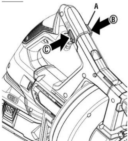
DIRECTION OF ROTATION SELECTOR (CLOCKWISE/COUNTERCLOCKWISE/CENTER LOCK)
See Figure 3, page 13.
Set the direction of rotation selector in the OFF (center lock) position to lock the switch trigger and help prevent accidental starting when not in use.
Position the direction of rotation selector to the left of the switch trigger in the F/R (forward/retract) position to rotate the cable clockwise. Position the selector to the right of the switch trigger in the N (neutral) position to rotate the cable counterclockwise.
NOTE: The tool will not run unless the direction of rotation selector is pushed fully to the left or right.
NOTE: For optimal performance, position both the direction of rotation selector and the direction of feed collar as described later in the Feed and Rotation Chart.
NOTICE:
To prevent gear damage, always allow the cable to come to a complete stop before changing the direction of rotation.

WARNING:
Hybrid tools are always in operating condition. Therefore, lock the switch trigger when not in use or carrying at your side, when installing or removing the battery pack, when connecting or disconnecting the power cord, and when manually advancing or retracting the cable. Failure to follow these instructions could result in serious personal injury.
VARIABLE SPEED SWITCH TRIGGER
See Figure 4, page 14.
The variable speed switch trigger delivers higher speed with increased trigger pressure and lower speed with decreased trigger pressure.
To turn the tool ON, depress the switch trigger. To turn it OFF, release the switch trigger and allow the cable to come to a complete stop.
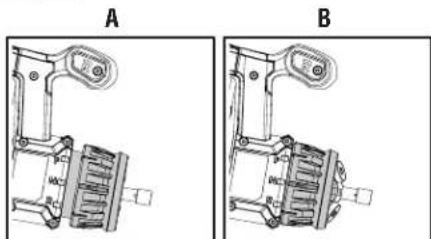
FEED DIRECTION SELECTOR COLLAR
See Figures 5 and 6, page 14.
The drain auger has three operating modes: forward (F), neutral (N), and retract (R). In the forward (F) position, squeezing the switch trigger will rotate and advance the cable. When the tool is in retract (R) position, the cable will rotate and retract as the switch trigger is squeezed. If the drain auger is in neutral (N), the cable will not rotate, advance, or retract.
NOTE: Never run the tool while the collar is pushed in and in the neutral (N) position. Doing so will cause the cable to kink.
To switch between modes:
■ Lock the switch trigger by placing the direction of rotation selector in OFF (center lock) position.
■ Pull the feed direction selector collar away from the tool and rotate it until the feed indicator is pointing at your desired operating mode.
■ Push the collar toward the drum until it clicks into place.
NOTE: The drum will rotate in the same direction regardless of the direction of feed.
NOTE: For optimal performance, position both the direction of rotation selector and the direction of feed collar as described later in the Feed and Rotation Chart.

WARNING:
Be careful when adjusting the feed direction selector collar, keep fingers and cord away from pinch points. Failure to heed this warning could result in fingers being pinched or the cord being damaged.
OPERATION
SELECTING THE RIGHT FEED AND ROTATION DIRECTION
See Figures 3 and 5, pages 13 and 14.
The drain auger works best when the direction of feed and the direction of rotation are coordinated properly. For example, when advancing the cable through a drain pipe, the direction of feed collar should be in the forward (F) position and the direction of rotation selector should be in the F/R (forward/retract) position. Advancing the cable, using any other rotation and feed direction combination will cause the drain auger to underperform. Refer to the Feed and Direction Chart to determine which rotation and feed directions are best for your application.
| FEED AND DIRECTION CHART | |||
| FEED DIRECTION | COLLAR | ROTATION DIRECTION | |
| Advance Cable | F | Pushed In | F/R |
| Not Recommended | F | Pushed In | N |
| Retract Cable | R | Pushed In | F/R |
| Not Recommended | R | Pushed In | N |
| Stationary (Rotate Clockwise) | N | Pulled Out | F/R |
| Stationary (Rotate Counter Clockwise) | N | Pulled Out | N |
| Physically Pull on Cable | N | Pushed In | Do Not Use |
ADVANCING/RETRACTING THE CABLE
See Figures 4 - 6, page 14.
To manually advance and retract the cable:
■ Lock the switch trigger by placing the direction of rotation selector in the OFF (center lock) position.
■ Pull the feed direction selector collar out and rotate it to the neutral (N) position.
- Hold the front handle with one hand and advance the cable with the other.
■ Advance the cable to your desired length.
■ To lock the cable in place, leave the feed direction selector collar in the neutral (N) position and push the collar in.
NOTE: The cable can't be advanced or retracted while the collar is pushed in and in the neutral (N) position.
NOTE: Never run the tool while the collar is pushed in and in the neutral (N) position. Doing so will cause the cable to kink.
■ To retract the cable, pull the feed direction selector collar out, hold the front handle with one hand, and pull the cable back with the other.
NOTICE:
Do not advance or retract the cable using the switch trigger unless the cable is in a drain pipe.
To advance and retract the cable using the switch trigger:
■ Connect the product to an AC or DC power supply.
■ Place the direction of rotation selector in the the F/R (forward/retract) position.
■ Pull the feed direction selector collar out and away from the tool.
■ Rotate the feed direction selector collar to the forward (F) position then push the collar in.
■ Squeeze and hold the switch trigger to advance the cable.
■ Advance the cable to your desired length.
■ To prevent the cable from advancing or retracting, pull the collar out away from the tool, rotate the feed direction selector collar to the neutral (N) position and push the collar in.
NOTE: The cable can't be advanced or retracted while the collar is pushed in and in the neutral (N) position.
NOTE: Never run the tool while the collar is pushed in and in the neutral (N) position. Doing so will cause the cable to kink.
■ To retract the cable using the switch trigger, place the feed direction selector collar in the retract (R) position, push the collar in, and squeeze the switch trigger.
NOTICE:
Do not run the drain auger in forward or reverse for extended periods of time. Failure to follow these instructions can result in damage to the tool.
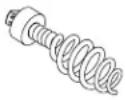
REMOVING/INSTALLING AUGER TIPS
See Figure 7, page 14.
Your drain auger is shipped with a standard bulb tip. This tip is ideal for extracting hair, paper, and other common obstructions. More auger tips are available at www.ryobitools.com and can be used to clear a variety of obstructions. Refer to the Auger Tip Selection Guide for information about which tip to choose.
OPERATION
To install an auger tip:
■ Remove the battery pack or power cord from the tool.
■ Hold the cable and pull the collar back.
- Slide the auger tip into into the cable’s t-slot.
■ Push the collar forward so that the tip is secured properly. Check to see that the tip is secure.
To remove an auger tip:
■ Remove the battery pack or power cord from the tool.
■ Hold the cable and pull the collar back.
■ Remove the auger tip by sliding it out of the t-slot in the collar.
| AUGER TIP SELECTION GUIDE | |
 | Bulb TipHelps clear away obstructions and residue; used for generic purpose cleaning in drains up to 2 in. wide. |
 | Grease TipHelps penetrate through grease blockages in drains up to 2 in. wide. |
 | Spade TipHelps break through tough blockages in drains up to 2 in. wide. |
 | Side CutterHelps extract grease build-up and residue from sides of pipe up to 2 in. wide. |
USING THE DRAIN AUGER
See Figures 8 - 9, page 14.
The drain auger can be used to clear obstructions from a variety of drains including sinks and bathtubs.
NOTE: This product can be used to clear drain pipes with minimum diameters of 0.75 in. and maximum diameters of 2 in.
To clear obstructions:
■ When removing an obstruction from a sink or a bathtub, it may be necessary to remove the stopper or overflow cover to gain access to the drain pipe.
■ Install the appropriate auger tip.
■ Connect the product to an AC or DC power supply.
- Hold the drain auger within four inches of the drain or overflow and manually feed the cable into the drain pipe.
NOTE: Advance the cable slowly at first. Advancing it too rapidly can result in twisting or binding.
■ After feeding about six inches of cable into the drain, you may begin advancing the cable using the switch trigger or continue advancing it manually.
■ The cable should advance freely through the drain pipe until it contacts the obstruction or is caught in a P-trap.
If the cable is caught in a P-trap, additional force or increased trigger pressure should be enough to advance it past the bend in the pipe.
■ If the cable has contacted an obstruction, there are two ways to remove it:
- Leave the direction of rotation selector in the F/R (forward/retract) position and continue squeezing the switch trigger. Hold the trigger for several seconds, allowing the tip of the cable to bore into the obstruction. If the cable stops rotating, release the switch trigger to avoid kinking or damaging the cable. Place the feed direction selector collar in the neutral (N) position, push the collar in, then push or pull the cable manually until the obstruction is dislodged. When finished, slowly retract the cable from the drain.
- Put the direction of rotation selector in the N (neutral) position. Place the feed direction selector collar in the neutral (N) position, then pull it out away from the tool. Squeeze the switch trigger. The cable will rotate, but it will not advance. Hold the trigger for several seconds, allowing the obstruction to wrap around the cable. If the cable stops rotating, release the switch trigger to avoid kinking or damaging the cable. When finished, slowly retract the cable and pull the obstruction through the drain.
NOTE: When removing the cable from a drain, remove it slowly to avoid "splash back".
NOTE: If the tip of the cable is entangled and difficult to remove, change the direction of rotation to N (neutral) and run the tool in neutral to unwind and disengage from the obstruction.
■ Once the obstruction is cleared, run water through your drain to confirm that the water is flowing freely.
■ After the cable has been properly cleaned, as described in the next section, store the unit for later use.
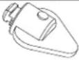
CLEANING THE DRAIN AUGER
See Figure 10, page 14.
The drain auger should be cleaned after each use to prevent contamination and residue build up.
To drain the drum:
■ Remove the battery pack or power cord from the tool.
- Hold the tool at an angle and lift the drain tab located on the back of the tool.
OPERATION
- Allow any liquids inside the drum to pour down a drain or into a container approved for liquid waste.
To clean the cable:
■ Remove the battery pack or power cord from the tool.
■ Using a clean cloth and warm soapy water, pull the cable out from the tool, cleaning it as it advances. Continue until the cable has been fully advanced and completely cleaned.
■ Using a clean, dry cloth, pull the cable back into the tool, drying it as it retracts. Continue until the cable has been fully retracted.
■ To ensure that no water entered the tool, drain the drum as described earlier.
NOTICE:
Do not advance or retract the cable using the switch trigger unless the cable is in a drain pipe.
MAINTENANCE

WARNING:
When servicing, use only identical replacement parts. Use of any other part could create a hazard or cause product damage.

WARNING:
To avoid serious personal injury, always remove the battery pack or power cord from the tool when cleaning, performing any maintenance, or when storing the tool.
GENERAL MAINTENANCE
Avoid using solvents when cleaning plastic parts. Most plastics are susceptible to damage from various types of commercial solvents and can be damaged by their use. Use clean cloths to remove dirt, dust, oil, grease, etc.

WARNING:
Do not at any time let brake fluids, gasoline, petroleum-based products, penetrating oils, etc., come in contact with plastic parts. Chemicals can damage, weaken or destroy plastic which could result in serious personal injury.
REPLACING THE AUGER TIP
After extended use, the auger tip may wear and need replacing. Refer to Removing/Installing Auger Tips earlier in this manual.
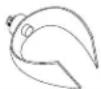
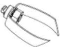
REPLACING THE DRUM
See Figures 11 - 12, page 14.
If the cable becomes damaged or broken, replace the drum before attempting to operate the drain auger.
To replace the drum:
■ Remove the battery pack or power cord from the tool.
■ Remove the auger tip as described earlier.
■ Pull the feed direction selector collar out and rotate it to the neutral (N) position.
■ Pull drum latch up to unlock the front portion of the tool.
NOTE: When opening the latch, hold the drum securely to prevent the drum from falling out.
■ Move the front portion of the tool forward (away from the drum) and pivot it up.
■ Pull the cable through the feed direction selector collar and into the old drum.
■ Pull the old drum off the spindle and remove it from the tool.
■ Place the new drum onto the spindle.
■ Feed the cable for the new drum through the feed direction selector collar and toward the front of the tool.
■ Tilt the front portion of the tool down and slide it back into place (toward the drum).
■ Push the drum latch down to lock the front portion of the tool in place.
■ Ensure that the latch, drum, and front portion of the tool are secure before operating the tool.
NOTE: ILLUSTRATIONS START ON PAGE 13 AFTER FRENCH AND SPANISH LANGUAGE SECTIONS.
NOTES
AVERTISSEMENTS DE SÉCURITÉ GÉNÉRALES RELATIVES AUX OUTILS ÉLECTRIQUES

AVERTISSEMENT
REPLACEMENT DU BOUT DU FURET
REPLACEMENT DU TAMBOUR
0-2,0 2,1-3,4 3,5-5,0 5,1-7,0 7,1-12,0 12,1-16,0
A - Battery pack (bloc-piles, paquete baterías)
B - Depress latches to remove battery pack (appuyer sur les loquets pour libérer le bloc-piles, para soltar el paquete de baterías, oprima los pestillos)
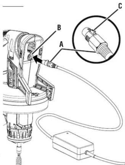
A - Power supply (female end) [alimentation électrique (femme restante), suministro de corriente (extremo hembra)]
B - AC receptacle (prise CA, receptáculo CA)
C - Release button (relâchez le bouton, botón de afloje)
A - Feed direction selector collar (collier de sélection du sens d'alimentation, collar selector de dirección de alimentación)
B - Indicator (indicateur, indicador)
C - Forward feed position (position pour faire sortir, posición de alimentación de avance)
D - Neutral position (position neutre, posición muerto)
E - Retract feed position (position pour rétracter, posición de alimentación de retracción)
Fig. 6
natural_image
Technical line drawings of mechanical components labeled A and B, showing internal parts without any text or symbols.A - Latch (loquet, pestillo)
Fig. 12
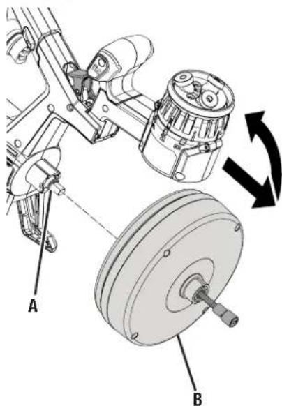
A - Spindle (broche, husillo)
B - Drum (tambour, tambor)
To request service, purchase replacement parts,
locate an Authorized Service Center or obtain Customer or Technical Support:
Visit www.ryobitools.com or call 1-800-525-2579
If any parts or accessories are damaged or missing, do not return this product to the store.
Call 1-800-525-2579 for immediate service.
Please obtain your model and serial number from the product data plate.
This product is covered under a 3-year limited Warranty. Proof of purchase is required.
MODEL NUMBER* ____ SERIAL NUMBER ____
*Model number on product may have additional letters at the end. These letters designate manufacturing information and should be provided when calling for service.
RYOBI is a trademark of Ryobi Limited and is used pursuant to a license granted by Ryobi Limited.