DXPH060E - Generator DEWALT - Free user manual and instructions
Find the device manual for free DXPH060E DEWALT in PDF.

| Product type | Forced air gas heater |
| Brand | DeWALT |
| Model | DXPH060E |
| Gas category | I3B/P, I3P |
| Gas type | G30 (butane) or G31 (propane) or their mixture |
| Max gas consumption (G30) | 1310 g/h |
| Max gas consumption (G31) | 1286 g/h |
| Nominal heat input | 18 kW |
| Gas inlet pressure | 1.5 bar |
| Power supply | 220-240 V ~ 50 Hz, 29 W |
| IP class | IPx4 |
| Gas inlet connection | G 1/4 LH |
| Ignition | Piezoelectric (igniter) |
| Fan | Built-in, requires power supply |
| Use | Outdoor only, well-ventilated area |
| Destination countries | GB, DE, FR, IT, NL, DK, SE, FI, NO |
| Warranty | 2 years |
Frequently Asked Questions - DXPH060E DEWALT
User questions about DXPH060E DEWALT
0 question about this device. Answer the ones you know or ask your own.
Ask a new question about this device
Download the instructions for your Generator in PDF format for free! Find your manual DXPH060E - DEWALT and take your electronic device back in hand. On this page are published all the documents necessary for the use of your device. DXPH060E by DEWALT.
USER MANUAL DXPH060E DEWALT
If you have questions or comments, contact us.
www.DEWALT.com
INSTRUCTION MANUAL
DEWALT®
LANGUAGES INCLUDED: ENGLISH, GERMAN, FRENCH, ITALIAN, DUTCH, FINNISH, SWEDISH, NORWEGIAN, DANISH
Gas Forced Air Heater DXPH060E, DXPH125E
CE
2531/20
EN 1596:1998+A1:2004
2531DL-0078
SAVE THESE INSTRUCTIONS
⚠ WARNING: READ INSTRUCTIONS CAREFULLY: Read and follow all instructions. Place instructions in a safe place for future reference. Do not allow anyone who has not read these instructions to assemble, adjust or operate the heater.
Definitions: Safety Guidelines
The definitions below describe the level of severity for each signal word. Please read the manual and pay attention to these symbols.
△ DANGER: Indicates an imminently hazardous situation which, if not avoided, will result in death or serious injury.
⚠ WARNING: Indicates a potentially hazardous situation which, if not avoided, could result in death or serious injury.
CAUTION: Indicates a potentially hazardous situation which, if not avoided, may result in minor or moderate injury. NOTICE: Indicates a practice not related to personal injury which, if not avoided, may result in property damage.
△WARNING: FIRE BURN, INHALATION, AND EXPLOSION HAZARD. KEEP SOLID COMBUSTIBLES, SUCH AS BUILDING MATERIALS, PAPER, OR CARDBOARD, A SAFE DISTANCE AWAY FROM THE HEATER AS RECOMMENDED BY THE INSTRUCTIONS. NEVER USE THE HEATER IN SPACES WHICH DO OR MAY CONTAIN VOLATILE OR AIRBORNE COMBUSTIBLES, OR PRODUCTS SUCH AS GASOLINE, SOLVENTS, PAINT THINNER, DUST PARTICLES OR UNKNOWN CHEMICALS.
⚠ WARNING: GENERAL HAZARD
FAILURE TO COMPLY WITH THE PRECAUTIONS AND INSTRUCTIONS PROVIDED WITH THIS HEATER, CAN RESULT IN DEATH, SERIOUS BODILY INJURY AND PROPERTY LOSS OR DAMAGE FROM HAZARDS OF FIRE, EXPLOSION, BURN, ASPHYXIATION, CARBON MONOXIDE POISONING, AND/OR ELECTRICAL SHOCK. ONLY PERSONS WHO CAN UNDERSTAND AND FOLLOW THE INSTRUCTIONS SHOULD USE OR SERVICE THIS HEATER. IF YOU NEED ASSISTANCE OR HEATER INFORMATION SUCH AS AN INSTRUCTIONS MANUAL, LABELS, ETC. CONTACT THE MANUFACTURER. SAVE THESE INSTRUCTIONS FOR FUTURE REFERENCE.
⚠ WARNING: THIS HEATER IS FOR OUTDOOR USE ONLY. AN AMPLY VENTILATED AREA MUST HAVE A MINIMUM OF 25% OF THE SURFACE AREA OPEN. THE SURFACE AREA IS THE SUM OF THE WALLS SURFACE.
△WARNING: NOT TO BE USED FOR THE HEATING OF HABITABLE AREAS OF DOMESTIC PREMISES; FOR USE IN PUBLIC BUILDINGS REFER TO NATIONAL REGULATIONS.
This heater is constructed in conformity with relevant texts in the EN1596:1998/A1:2004 standard. INSTALL THIS DEVICE ONLY WHEN IT COMPLIES WITH LOCAL/NATIONAL LEGISLATION, ORDINANCES AND STANDARDS.
CONTENTS
| WARNINGS 2 |
| HEATER SPECIFICATIONS 3 |
| Odour FADE WARNINGS 4 |
| SAFETY PRECAUTIONS 5 |
| LIGHTING/OPERATING INSTRUCTIONS 6 |
| MAINTENANCE 7 |
| TROUBLESHOOTING 9 |
| WIRING DIAGRAM 9 |
| EXPLODED VIEW AND PARTS LIST 10 |
| LIMITED WARRANTY 12 |
Heater Specifications
| Model DXPH060E DXPH125E | ||||
| Gas Category | I3B/P I3P I3B/P I3P | |||
| Gas Type | G30/G31 or their mixture G31 | G30/G31 or their mixture G31 | ||
| Gas Consumption (max.) | G30 1310 g/h G31 1286 g/h 1286 g/h G30 2547 g/h G31 2501 g/h 2501 g/h | |||
| Destination Countries | GB, DE, FR, IT, NL, DK, SE, FI, NO | GB, DE, FR, IT, NL, DK, SE, FI, NO | GB, DE, FR, IT, NL, DK, SE, FI, NO | GB, DE, FR, IT, NL, DK, SE, FI, NO |
| Nominal Heat Input 18 kW 35 kW | ||||
| Input Pressure 1.5Bar | ||||
| Original Country | China | |||
| Electrical Data | 220 - 240V 50Hz 29W | 220 - 240V 50Hz 44W | ||
| PIN | 2531DL-0078 | |||
| IP class | IPx4 | |||
| Gas Inlet connector | G 1/4 LH | |||
NOTE: The heat input of Model DXPH125E is adjustable from 20kW to 35kW.
- Do not use in unventilated areas
- The flow of combustion and ventilation air must not be obstructed
- Proper ventilation air must be provided to support the combustion air requirements of the heater being used.
- Refer to the specification section of the heater's manual, heater dataplate, or contact the factory to determine combustion air ventilation requirements of the heater.
- Lack of proper ventilation air will lead to improper combustion
- Improper combustion can lead to carbon monoxide poisoning leading to serious injury or death. Symptoms of carbon monoxide poisoning can include headaches, dizziness and difficulty in breathing.
- Use only in a well ventilated area and away from combustible materials.
- Ensure that the fan is operating correctly before lighting the burners.
Fuel Gas Odour
LP gas and natural gas have man-made odourants added specifically for detection of fuel gas leaks. If a gas leak occurs you should be able to smell the fuel gas. Since Propane (LP) is heavier than air you should smell for the gas odour low to the floor. ANY GAS Odour IS YOUR SIGNAL TO GO INTO IMMEDIATE ACTION!
- Do not take any action that could ignite the fuel gas.
- Do not operate any electrical switches.
- Do not pull any power supply or extension cords.
- Do not light matches or any other source of flame.
- Do not use your telephone.
- Get everyone out of the building and away from the area immediately. Close all propane (LP) gas tank or cylinder fuel supply valves, or the main fuel supply valve located at the meter if you use natural gas.
• Propane (LP) gas is heavier than air and may settle in low areas. When you have
reason to suspect a propane leak, keep out of all low areas.
- Use a telephone remote from the area of the leak and call your fuel gas supplier and your fire department. Do not re-enter the building or area.
- Stay out of the building and away from the area until declared safe by the firefighters and your fuel gas supplier.
- FINALLY, let the fuel gas service person and the firefighters check for escaped gas. Have them air out the building and area before you return. Properly trained service people must repair any leaks, check for further leakages, and then relight the appliance for you.
Odour Fading - No Odour Detected
- Some people cannot smell well. Some people cannot smell the odour of the man-made chemical added to propane (LP) or natural gas. You must determine if you can smell the odourant in these fuel gases.
- Learn to recognize the odour of propane (LP) gas and natural gas.
- Smoking can decrease your ability to smell. Being around an odour for a period of time can affect your sensitivity to that particular odour. Odours present in animal confinement buildings can mask fuel gas odour.
- The odourant in propane (LP) gas and natural gas is colorless and the intensity of its odour can fade under some circumstances.
- If there is an underground leak, the movement of gas through the soil can filter the odourant.
- Propane (LP) gas odour may differ in intensity at different levels. Since Propane (LP) gas is heavier than air, there may be more odour at lower levels.
- Always be sensitive to the slightest gas odour. If you continue to detect any gas odour, no matter how small, treat it as a serious leak. Immediately go into action as discussed previously.
ATTENTION - Critical Points to Remember!
- Propane (LP) gas has a distinctive odour. Learn to recognize these odours. (Reference Fuel Gas Odour and Odour Fading sections on this same page)
- Even if you are not properly trained in the service and repair of the heater, ALWAYS be consciously aware of the odours of propane (LP) gas and natural gas.
- If you have not been properly trained in repair and service of propane (LP) gas then do not attempt to light heater, perform service or repairs, or make any adjustments to the heater on the propane (LP) gas fuel system.
- A periodic sniff test around the heater or at the heater's joints; i.e. hose, connections, etc., is a good safety practice under any conditions. If you smell even a small amount of gas, CONTACT YOUR FUEL GAS SUPPLIER IMMEDIATELY. DO NOT WAIT!
THIS IS A HEATING APPLIANCE. DO NOT ATTEMPT TO WARM OR COOK FOOD ON THIS HEATER.
-
Check the heater thoroughly for damage. DO NOT operate a damaged heater.
-
DO NOT modify the heater or operate a heater which has been modified from its original condition.
-
Use only propane gas.
-
Use only VAPOR WITHDRAWAL propane supply. If there is any question about vapor withdrawal, ask your propane dealer.
-
Mount the propane cylinders vertically (shutoff valve up). Secure them from falling or being knocked over and protect them from damage.
-
This heater is for outdoor use only. An amply ventilated area must have a minimum of 25% of the surface area open. The surface area is the sum of the walls surface.
-
If at any time gas odour is detected, IMMEDIATELY DISCONTINUE operation until the source of gas has been located and corrected.
-
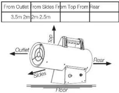
Maintain minimum clearance from normal combustible material per requirements stated in Figure 1.
-
Due to the high surface and exhaust temperatures, children and pets must be kept away from this appliance when is use.
-
Operate only on a stable, level surface.
-
Use only the electrical power specified. If the power cord is damaged, it shall be repaired by the manufacturer, its service agent or similarly qualified persons in order to avoid hazard.
-
Use only a properly grounded 3-prong receptacle or extension cord.
-
Do not move, handle or service while hot or burning.
-
Install this device and store gas cylinder in accordance with local/national legislation, ordinances and standards.
-
Do not cover the appliance when using.
-
Do not use the appliance without the front and rear guards in place. The guards are designed for protection.
-
In case of violent wind, particular attention must be taken against tilting of the appliance.
-
Have any repairs and/or maintenance carried out by a recognized service technician only.
-
This appliance is designed for using the 1.5bar gas regulator complying with the EN 16129 and revelant requirement. If you have any doubt, please contact your local dealer.
Ventilation Requirements
- For every kW it is necessary to have permanent ventilation of 25 cm ^2 , equally distributed between the floor and high level, with a minimum outlet of 250 cm ^2 .
• Never direct the hot air flow towards the cylinder. - Never use the heater without its cover.
- Do not exceed 100 ~W / m^3 of free room. The minimum volume of the room must be larger than 100 ~m^3 .
- The heater must be placed where there is no risk of fire. The hot air outlet must be at least 3.5m from any flammable wall or ceiling and must never be directed towards the gas cylinder. If in any doubt contact your supplier.
- Do not use duct work. Do not obstruct the inlet or outlet sections of the heater.
- Do not use the heater in cellars, basements or in any room below the ground level.
- If the heater has to work for a long period at its maximum capacity, it's possible that ice will form on the cylinder. This is due to excessive vapour withdrawal. Not for this reason, or for any other, should the cylinder be heated. To avoid this effect, or at least to reduce it, use a large cylinder or two cylinders linked together.
- The manufacturer is not responsible for any harm or damage if attention is not paid to the points described above. The use of this product and the elements required for that purpose is entirely at the end user's own risk.
Figure 1: Minimum Clearances from combustible material
- Use propane, butane or their mixture only. See rating label on the appliance.
- The appliance requires approved gas hose in <150 cm length and a gas regulator. The hose and regulator assembly must conform to local standard codes.
• Regulator maximum inlet pressure must not exceed 690 kPa. - Gas connection .635 cm LH is to be used with 1.5Bar regulator. Gas connection .9525 cm LH is to be used with 0-2 bar regulator (when in need).
• This appliance is designed for gas cylinders up to 15 kg. - A dented, rusted or damaged gas cylinder may be hazardous and should be checked by an authorized dedicated gas specialist. Never use a gas cylinder with a damaged valve connection.
- Never connect an unregulated gas cylinder to the heater.
- Never twist the flexible tubes and hoses. Torsional stress on tubes and hoses might lead to gas leakage over time.
- The installation of the gas cylinder must conform to local codes, or in the absence of local codes, to the standard for the storage and handling of liquid petroleum gases.
- Disconnect the gas cylinder when the heater is not use.
- Isolate the appliance from the cylinder by means of the cylinder isolating valve when not in operation.
Leak Testing
Gas connections on the heater are leak tested at the factory prior to shipment. A complete gas tightness check must be performed at the installation site due to possible mishandling in shipment and/or installation or because of excessive pressure being applied to the heater. The heater must be checked with a full cylinder.
-
Make sure the safety control valve is in the OFF position.
-
Make a soapy water solution of one part liquid detergent and one part water. The soapy water solution can be applied with a spray bottle, brush or rag to all gas connections.
⚠ WARNING: Never leak test while smoking! In the event of gas leakage, the appliance must not be used or if still lit, the gas supply must be shut off and the leakage repaired before it can be used again.
-
Turn the gas supply ON. And check all the connections with the soapy water solution. Soap bubbles will appear in case of a leak.
-
In case of a leak, turn off the gas supply. Tighten any leaking fittings, then turn the gas supply ON and recheck. Contact your dealer or gas supplier for assistance if bubbles continue to appear.
Lighting/Operating Instructions Preparation for Operation
- Remove the heater from the box and check for possible shipping damage. If any is found, immediately notify the factory.
- Open the handle and screw plastic bag.
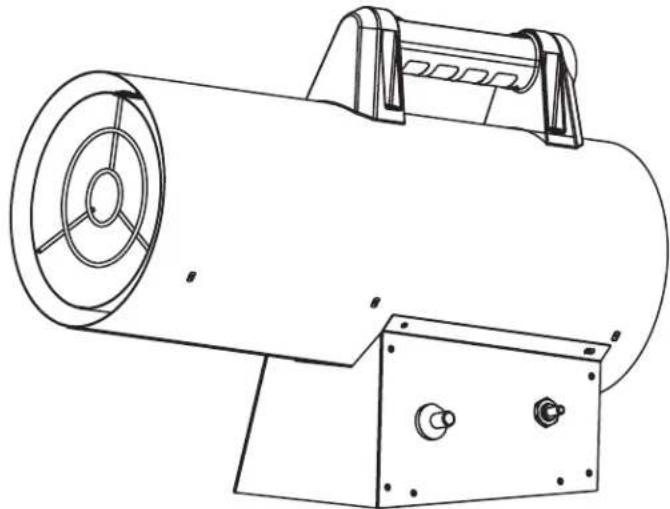
- Secure the handle to the heater with the four screws provided through the four holes at the top of the unit. See Figure 2.
NOTE: A gas hose and gas regulator are NOT included with the heater. - Connect the gas supply hose to the pressure regulator and connect the regulator to a suitable gas cylinder.
- Connect the hose to the gas connector on the heater by rotating the hose fitting clockwise.
- Open the cylinder's gas valve and check all gas connections with a soap and water solution as described above.
- Connect power cord to well-grounded 220V\~240V, 50Hz source of power.

natural_image
Technical line drawing of a cylindrical mechanical device with mounting brackets and internal components (no text or symbols)Figure 2
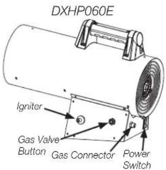
- Turn the power switch to the ON (I) position to start the fan.
NOTE: Before heater ignition, always allow heater fan (blower) to run for 20 seconds to purge fuel. - Slowly open the main valve at propane cylinder.
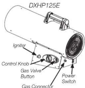
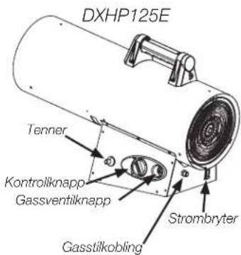
- Push the gas valve button and push the ignitor (piezoelectric lighter) repeatedly until the flame lights up.
- After the heater lights, keep the valve button pushed for approximately 10 seconds. Should the heater stop when the valve button has been released, wait one minute and repeat the starting operation, keeping the valve button pushed for a longer time.
- On the DXPH125E model only, rotate the control knob to the lowest setting. After the heater lights, you may adjust the burn rate by setting the control knob to desired level.
NOTE: Contact your supplier should any problem continue.
⚠CAUTION: If ignition is difficult or irregular before repeating the starting steps, make sure that the fan is not locked and the air inlet and outlet are unobstructed.
Stopping Heater
- Securely close valve on the propane cylinder.
- Continue to operate heater until all fuel in the hose has burned then turn power switch to the OFF (O) position.
- Unplug the power cord.
△CAUTION: Always shut off fuel supply:
• Before disconnecting electrical power
• Before moving the appliance
• After each use
RESTART AFTER SAFETY SHUTDOWN
- Securely close valve at propane cylinder. Unplug power cord.
- Wait 5 minutes.
- Restart following "START" procedure.
NOTE: If a new tank has just been connected, please allow at least one minute or more for the air in the gas pipeline to purge out through the pilot hole.
⚠ WARNING: Always keep a dry chemical fire extinguisher readily available.
FAN OPERATION
- The appliance may also be used as a fan.
- In this case remove the gas supply hose and connect the plug of heater to a suitable electrical supply.
- Set the power switch to the ON (l) position.
REPLACING THE GAS CYLINDER
- Shut off the heater.
- Close the valve of the gas cylinder.
- Disconnect the regulator from the cylinder following the instructions that came with your regulator.
- Replace the cylinder.
⚠ WARNING: Only remove the plug or seal cap from the cylinder valve and change the gas cylinder in a amply ventilated area, away from any ignition source (candle, cigarettes, and other flame producing appliances). - Check for the presence and good state of the gasket before connecting the regulator to the new cylinder.
- Check that the regulator seal is correctly fitted and able to fulfil its function.
- Perform leak test using soapy water solution.
Maintenance
- The heater should be inspected before each use, and at least annually, only by a qualified person. Before starting any maintenance operation on the heater, disconnect from both gas and electrical sources.
WARNING: The whole gas system. hose, regulator, pilot and burner should be inspected for leak before use. But at least once a month and each time the gas cylinder is changed. Check the hose assembly for sign of extreme abrasion, cuts or wears. Suspected areas should be leak tested. If the hose leaks, it must be replaced with a new one that conforms to local standard codes). If it shows signs of cracking, splitting or other deterioration it shall be exchanged for new hose of the same length and of the equivalent quality. Replace the gas tube/hose within the interval described with the hose.
If the unit has not been used for a long period we advise that a technician carries out a general check up before using. It is important to perform the following:
- Periodically check the gas supply hose conditions and, should it be changed, use only original spare parts.
- Check the connections of the safety thermostat and of the thermocouple: they must always be clean. If necessary clean the fan blade and the inside of the heater using compressed air.
A hazardous condition may result if a heater is used that has been modified or is not functioning properly. When the heater is working properly:
* The flame is contained within the heater.
* The flame is essentially blue with perhaps some yellow tipping.
* There is no strong disagreeable odour, eye burning or other physical discomfort.
* There is no smoke or soot internal or external to the heater.
* There are no unplanned or unexplained shut downs of the heater.
The parts lists and exploded view show the heater as it was constructed. Do not use a heater which is different from that shown. In this regard, use only the hose, regulator and cylinder connection fitting (called a POL fitting) supplied with the heater. IMPORTANT Match the color stripe on the hang tag attached to the hose assembly with the color on the label located near the propane inlet fitting on the heater. Do not use alternates. For this heater, the regulator comes factory set as shown in "specifications". If there is any uncertainty about the regulator setting, have it checked.
A heater which is not working right must be repaired, but only by a trained, experienced service person.
In-warranty products will be repaired with no charge for either parts or labor. Please include a brief statement indicating date, place of purchase, the nature of the problem and proof of purchase.
Out-of-warranty products will be repaired with a charge for parts and labor.
Storage
• Make sure the heater is in off position.
- Turn off the gas at the LP-gas supply cylinder(s) when the heater is not in use.
- Disconnect the gas container from the gas heater.
- Store the gas container in a cool, dry, dark and well-ventilated room. A disconnected cylinder must have threaded valve plugs tightly installed. Position it far away from inflammable, explosive or hot materials and preferably not in the home. In addition it should never be stored in the basement or attic.
- Cylinder must be stored out of the reach of children.
- Do not store or use gasoline or other flammable vapors and liquids in the vicinity of this or any other appliance.
- When the heater is to be stored indoors, the connection between the LP-gas supply cylinder(s) and the heater must be disconnected and the cylinder(s) removed from the heater and stored out of doors.
- Check the tightness of the gas valve and for damage. If you suspect a damage, have it changed by your gas dealer.
Cleaning and Care
⚠ WARNING: Make sure the heater is in off position and is cool. Do not clean heater with cleaners that are combustible or corrosive.
- Wipe off powder coated surfaces with soft, moist rag and soap water.
- Remove debris and spider and insect nests from ventilation opening of the cylinder enclosure, control compartment, burner and circulation air passageways of the heater with heavy duty pipe cleaner or compressed air to keep appliance clean and safe for use.
- Never clear ports or other openings with toothpicks or other article that will break and block the ports.
Troubleshooting
NEVER LEAVE THE HEATER UNATTENDED WHILE BURNING!
| PROBLEM CAUSE SOLUTIONS | ||
| The motor does not work No electricity | supply Check the terminal board with a tester | |
| The motor works, but the burner does not light up and after few seconds the heater stops | The cylinder gas tap is closed Open the gas tap | |
| The cylinder is empty Use a new cylinder | ||
| The nozzle is obstructed Remove the nozzle and clean it | ||
| The solenoid gas valve is not open Check that the solenoid valve works | ||
| There is no spark Check the position of electrode | ||
| The burner lights up, but after few seconds the heater stops | Heater not properly grounded Check and connect properly | |
| Defective connection between sensor and safety device Check and connect properly | ||
| Defective safety device Replace the safety device | ||
| The heater stops during operation Excessive gas supply Check the pressure reducer and if required replace it | ||
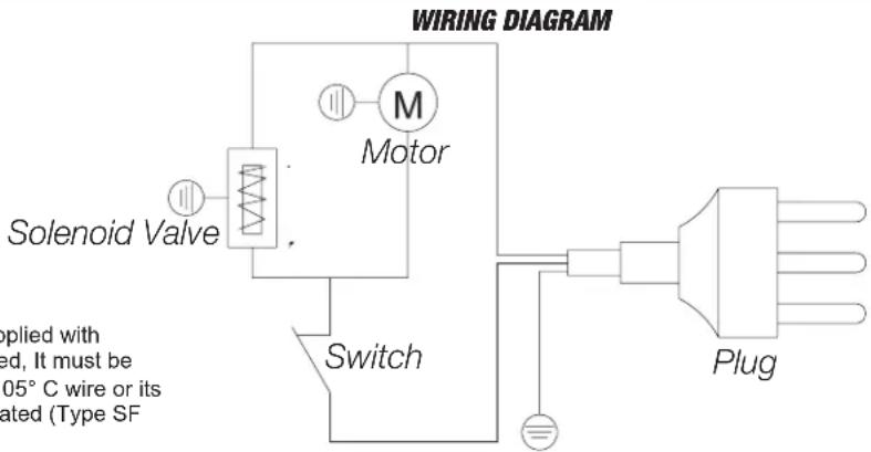
If any original wiring as supplied with the heater, must be replaced, It must be replaced with Type AWG 105°C wire or its equivalent, except as indicated (Type SF 2.200, **SGI-250°C)
DXPH060E & DXPH125E REPLACEMENT PARTS LIST
| # | 60K125K | DescriptionQty | # | 60K125K | DescriptionQty | ||
| 1 | 20989 20978 | Outlet Retainer 1 | 14 | 40801 40801 Handle | 1 | ||
| 2 | 20954 20979 | Combustion Chamber 1 | 15 | 20962 20985 Base Rear Panel | 1 | ||
| 3 | 20914 20925 | Outer Barrel 1 | 16 | 20976 20975 High Limit Switch | 1 | ||
| 4 | 20955 20980 | Base Front Panel 1 | 17 | 20964 20964 Switch | 1 | ||
| 5 | 20956 20981 | Base Left Panel (DXPH125E Shown) 1 | 18 | 20965 20965 Electric Supply Cord (J-Type) | 1 | ||
| 6 | 20957 20957 | Igniter 1 | 20966 20966 Electric Supply Cord (F-Type) | 1 | |||
| 7 | N/A 20982 Control Knob | 20967 20967 Electric Supply Cord (G-Type) | 1 | ||||
| 8 | N/A 20983 Decorative Panel | 1 | 19 | 20968 20986 Inlet Retainer | 1 | ||
| 9 | 20920 20931 | Base Bottom Panel | 1 | 20 | 20969 20987 Fan Motor | 1 | |
| 10 | 20977 20958 | Burner Supply Tube | 1 | 21 | 20970 20970 Orifice Nut | 1 | |
| 11 | 20959 20984 | Valve Assembly | 1 | 22 | 20971 20988 Orifice | 1 | |
| 12 | 20974 20968 | Burner Assembly | 1 | 23 | 20972 20972 Thermocouple | 1 | |
| 13 | 20916 20927 | Base Right Panel (DXPH125E Shown) | 1 | 24 | 20973 20973 Igniter Electrode | 1 |
natural_image
Technical line drawing of a cylindrical industrial device with mounting bracket and side rotor (no text or symbols)Warning
USE ONLY MANUFACTURER'S REPLACEMENT PARTS. USE OF ANY OTHER PARTS COULD CAUSE INJURY OR DEATH. REPLACEMENT PARTS ARE ONLY AVAILABLE DIRECT FROM THE FACTORY AND MUST BE INSTALLED BY A QUALIFIED SERVICE AGENCY.
PARTS ORDERING INFORMATION:
PURCHASING: Accessories may be purchased at any DEWALT® local dealer or direct from the factory.
FOR INFORMATION REGARDING SERVICE:
www.DEWALT.com
www.2helpU.com
Please include the model number, date of purchase, and description of problem in all communication.
LIMITED WARRANTY
DeWalt® warrants its heaters and accessories to be free from defects in material and workmanship for a period of 2 years from date of purchase.
DeWalt® will repair or replace this product free of charge if it has been proven to be defective within the 2 year period, and is returned at customer expense with proof of purchase to DeWalt® within the warranty period.
For Sale in the following countries:

GB

DK

DE

SE

FR

FI

IT

NO

NL
DeWALT®, GUARANTEED TOUGH® and the yellow and black color scheme are trademarks of the DeWALT Industrial Tool Co., used under license. ©2020 DeWALT. EGI/Enerco Group Inc. Under license from DeWALT Industrial Tool Co

2531/20
EN 1596:1998+A1:2004
2531DL-0078
⚠️ WARNUNG: ALLGEMEINE GEFAHR
DXPH060E & DXPH125E REPLACEMENT PARTS LIST
natural_image
Technical line drawing of a cylindrical industrial device with mounting bracket and side ports (no text or symbols)⚠️Warnung
INSTRUCTIONS D'ALLUMAGE / DE FONCTIONNEMENT
MAINTENANCE 7
DÉPANNAGE 9
SCHÉMA DE CÂBLAGE 9
NE JAMAIS LAISSER L'APPAREIL DE CHAUFFAGE SANS SURVEILLANCE QUAND IL FONCTIONNE
LISTE DES PIÈCES DE RECHANGE DXPH060E ET DXPH125E
natural_image
Technical line drawing of a cylindrical industrial device with mounting bracket and side slots (no text or symbols)Avertissement
UTILISEZ UNIQUEMENT DES PIÈCES DE RECHANGE DU FABRICANT. L'UTILISATION D'AUTRES PIÈCES POURRAIT PROVOQUER DES BLESSURES OU LA MORT. LES PIÈCES DE RECHANGE SONT DISPONIBLES UNIQUEMENT À L'USINE ET DOIVENT ÊTRE INSTALLÉES PAR UNE AGENCE DE SERVICE QUALIFIÉE.
natural_image
Technical line drawing of a cylindrical industrial device with mounting brackets and control panel (no text or symbols)Figure 2
NON LASCIARE MAI IL RISCALDATORE INCUSTODITO DURANTE LA COMBUSTIONE!
ELENCO COMPONENTI DI RICAMBIO DXPH060E & DXPH125E
natural_image
Technical line drawing of a cylindrical industrial device with mounting bracket and side slots (no text or symbols)Avvertenza
UTILIZZARE SOLO COMPONENTI DI RICAMBIO DEL COSTRUTTORE, L'UTILIZZO DI ALTRE COMPONENTI POTREBBE CAUSARE LESIONI O MORTE. I COMPONENTI DI RICAMBIO SONO DISPONIBILI SOLO DIRETTAMENTE DALLA FABBRICA E DEVONO ESSERE INSTALLATI DA UN CENTRO DI ASSISTENZA QUALIFICATO.
⚠ WAARSCHUWING: ALGEMEEN GEVAAR
HET NIET NALEVEN VAN DE VOORZORGSMAATREGELEN EN INSTRUCTIES MEEGELEVERD MET DEZE KACHEL KAN LEIDEN TOT DE DOOD, ERNSTIG LETSEL EN SCHADE AAN EIGENDOMMEN OF SCHADE DOOR GEVAAR VOOR BRAND, EXPLOSIE, VERBRANDING, VERSTIKKING, KOOLMONOXIDEVERGIFTIGING EN/OF ELEKTRICITEIT. ALLEEN PERSONEN DIE DE INSTRUCTIES BEGRIJPN EN OPVOLGEN, MOGEN DEZE KACHEL GEBRUIKEN OF ONDERHOUDEN. INDIEN U ONDERSTEUNING OF INFORMATIE OVER DE KACHEL NODIG HEEFT ZOALS EEN HANDLEIDING, LABELS, ENZ. NEEM DAN CONTACT OP MET DE FABRIKANT. BEWAAR DEZE INSTRUCTIES VOOR TOEKOMSTIG GEBRUIK.
⚠ WAARSCHUWING: DEZE KACHEL IS UITSLUITEND VOOR BUITENS-HUIS GEBRUIK. EEN VOLLEDIG GEVENTILEERDE RUIMTE MOET MINIMAAL 25% VAN DE OPPERVLAKTE VRIJ HEBBEN. DE TOTALE OPPERVLAKTE IS DE SOM VAN HET WANDOPPERVLAK.
⚠ WAARSCHUWING: NIET TE GEBRUIKEN VOOR DE VERWARMING VAN RUIMTES BEDOELD VOOR BEWONING; VOOR GEBRUIK IN PUBLIEKE RUIMTES RAADPLEEG DE NATIONALE REGELGEVING.
Deze kachel is gemaakt conform de relevante van de EN1596:1998/A1:2004 standard. INSTALLEER DIT APPARAAT ALLEEN ALS HET VOLDOET AAN LOKALE/NATIONALE WETGEVING, VERORDENINGEN EN NORMEN.
INHOUD
| WAARSCHUWINGEN 2 | |
| KACHEL SPECIFICATIES 3 | |
| ODOR FADE WARNINGS 4 | |
| GEURVERVAGINGSWAARSCHUWINGEN | 5 |
| VERLICHTING/BEDIENINGSINSTRUCTIES | 6 |
| ONDERHOUD 7 | |
| PROBLEEMOPLOSSEN 9 | |
| SCHAKELSCHEMA 9 | |
| EXPLOSIETEKENING EN ONDERDELEN LJST | 10 |
| BEPERKTE GARANTIE 12 | |
LAAT EEN BRANDENDE KACHEL NOOIT ONBEHEERD ACHTER!
Kachel Specifications
| Model DXPH060E DXPH125E | ||||
| Gas Categorie | I3B/P I3P I3B/P I3P | |||
| Gas Type | G30/G31 of mix daarvan G31 | G30/G31 of mix daarvan G31 | ||
| Gas Verbruik (max.) | G30 1310 g/h G31 1286 g/h | 1286 g/h | G30 2547 g/h G31 2501 g/h | 2501 g/h |
| Bestemmingslanden | GB, DE, FR, IT, NL, DK, SE, FI, NO | GB, DE, FR, IT, NL, DK, SE, FI, NO | GB, DE, FR, IT, NL, DK, SE, FI, NO | GB, DE, FR, IT, NL, DK, SE, FI, NO |
| Nominale Warmte Inbreng | 18 kW 35 kW | |||
| Ingangsdruk | 1.5Bar | |||
| Land van Oorsprong | China | |||
| Elektrische Specificaties | 220 - 240V 50Hz 29W | 220 - 240V 50Hz 44W | ||
| PIN | 2531DL-0078 | |||
| IP class | IPx4 | |||
| Gasinlaat-verbinding | G 1/4 LH | |||
LAAT EEN BRANDENDE KACHEL NOOIT ONBEHEERD ACHTER!
DXPH060E & DXPH125E REPLACEMENT PARTS LIST
natural_image
Technical line drawing of a cylindrical industrial device with mounting bracket and side ports (no text or symbols)Waarschuwing
GEBRUIK ALLEEN VERVANGINGSONDERDELEN VAN DE FABRIKANT. GEBRUIK VAN ANDERE ONDERDELEN KAN LETSEL OF DE DOOD VEROORZAKEN. VERVANGINGSONDERDELEN ZIJN ALLEEN DIRECT VERKRIJGBAAR IN DE FABRIEK EN MOETEN WORDEN GEINSTALLEERD DOOR EEN GEKWALIFICEERD ONDERHOUDSMONTEUR.
BESTELINFORMATIE VOOR DE ONDERDELEN:
ÄLÄ KOSKAAN JÄTÄ LÄMMITINTÄ ILMAN VALVONTAA SEN PALAESSA
DXPH060E JA DXPH125E VARAOSALUETTELO
natural_image
Technical line drawing of a cylindrical industrial device with mounting bracket and side slots (no text or symbols)Varoitus
KÄYTÄ VAIN VALMISTAJAN VARAOSIA. MUIDEN OSIEN KÄYTTÖ VOI AIHEUTTAA VAMMOJA TAI KUOLEMAN. VARAOSIA ON SAATAVANA VAIN SUORAAN TEHTAALTA JA NIIDEN ASENNUS ON ANNETTAVA PÄTEVÄN HUOLTOEDUSTAJAN TEHTÄVÄKSI.
OSIEN TILAUSTIEDOT:
⚠️ WARNING: ALLMÄN FARA
MISSLYCKAN MED ATT UPPFYLLA DE FÖRSIKTIGHETSÄTGÄRDER OCH ANVISNINGAR SOM TILLHANDAHÅLLS MED DENNA VÄRMARE, KAN LEDA TILL DÖDSFALL, ALLVARLIGA KROPPSSKADOR OCH FÖRLUST AV EGENDOM ELLER SKADA GENOM BRAND, EXPLOSION, BRAND, KVÄVNING, KOLMONOXIDFÖRGIFTNING, OCH/ ELLER ELEKTRISK CNOCK. ENDAST PERSONER SOM KAN FÖRSTÅ OCH KAN FÖLJA DENNA INSTRUKTION BÖR ANVÄNDA ELLER SERVA DENNA VÄRMEFLÄKT. OM DU BEHÖVER ASSISTANS ELLER INFORMATION OM VÄRMAREN, SÅSOM EN INSTRUKTIONS MANUAL, ETIKETTER, ETC. KONTAKTA TILLVERKAREN OCH SPARA DESSA INSTRUKTIONER FÖR FRAMTIDA REFERENS.
⚠️VARNING: DENNA BYGGVÄRMEFLÄKT ÄR ENDAST TILL FÖR UTOMHUSBRUK. ETT RIKLIGT VENTILATERAT OMRÅDE SOM MINST HAR 25 PROCENT YTA SOM ÄR ÖPPEN. YTOMRÅDET ÄR SUMMAN AV VÄGGENS YTA.
⚠️WARNING: EJ FÖR ANVÄNDNING I BEBOELIGA OMRÅDEN SOM HEM MILJÖER; FÖR ANVÄNDNING TILL UPPVÄRMNING AV OFFENTLIGA BYGGNADER HÄNVISA TILL NATIONELLA FÖRORDNINGAR.
natural_image
Technical line drawing of a cylindrical mechanical device with mounting brackets and internal components (no text or symbols)Bild 2
LÄMNA ALDRIG VÄRME ELEMENTET UTAN TILLSYN VID ANVÄNDNING!
Starta Värmefläkten
LÄMNA ALDRIG VÄRME ELEMENTET UTAN TILLSYN VID ANVÄNDNING!
DXPH060E & DXPH125E Bytesdelar lista
natural_image
Technical line drawing of a cylindrical industrial device with mounting bracket and side slots (no text or symbols)▲ Varning
ANVÄND ENDAST ERSÄTTNINGSDELAR FRÅN TILLVERKAREN. ANVÄNDNING AV ANDRA DELAR KAN ORSAKA SKADA ELLER DÖD. ERSÄTTNINGSDELAR ÄR BARA TILLGÄNGLIGA DIREKT FRÅN FABRIKEN OCH MÅSTE INSTALLERAS AV EN KVALIFICERAD SERVICE FÖRMEDLING.
BESTÄLLNING AV DELAR INFORMATION:
FÖR INFORMATION OM SERVICE:
www.DEWALT.com
www.2helpU.com
UMIDDELBAR HANDLING!
natural_image
Technical line drawing of a cylindrical device with mounting brackets and a circular vent, no text or symbols present.Figur 2
FORLAT ALDRI VARMEAPPARATET UTEN TILSYN MENS DET BRENNER!
Starte varmeapparatet
FORLAT ALDRI VARMEAPPARATET UTEN TILSYN MENS DET BRENNER!
DXPH060E & DXPH125E REPLACEMENT PARTS LIST
| #60K125KBeskrivelse | Antall | #60K125KBeskrivelse | Antall | ||||||
| 1 20989 20978 | Utløpssplint | 1 | 14 40801 40801 Håndtak | 1 | |||||
| 2 20954 20979 | Forbrenningskammer | 1 | 15 20962 20985 Bakre panel | sokkel | 1 | ||||
| 3 20914 20925 | Ytre tonne | 1 | 16 20976 20975 Høy grensebryter | 1 | |||||
| 4 20955 20980 | Frontpanel | sokkel | 1 | 17 20964 20964 Bryter | 1 | ||||
| 5 20956 20981 | Venstre panel | sokkel (DXPH125E vist) | 1 | 18 20965 20965 Strømledning (J-type) | 1 | ||||
| 6 20957 20957 | Tenner | 1 | 20966 20966 Strømledning (F-type) | 1 | |||||
| 7 | Ingen | 20982 Kontrollknapp | 1 | 20967 20967 Strømledning (G-type) | 1 | ||||
| 8 | Ingen | 20983 Dekorativt panel | 1 | 19 20968 20986 Innløpssplint | 1 | ||||
| 9 20920 20931 | Nedre panel | sokkel | 1 | 20 20969 20987 Viftemotor | 1 | ||||
| 10 20977 20958 | Tilforselsrø for brenner | 1 | 21 20970 20970 Åpningsmutter | 1 | |||||
| 11 20959 20984 | Ventilanordning | 1 | 22 20971 20988 Åpning | 1 | |||||
| 12 20974 20968 | Brenneranordning | 1 | 23 20972 20972 Termoelement | 1 | |||||
| 13 20916 20927 | Høyre panel | sokkel (DXPH125E vist) | 1 | 24 20973 20973 Tennerelekrode | 1 | ||||
FORLAT ALDRI VARMEAPPARATET UTEN TILSYN MENS DET BRENNER!
DEWALT®
BRUKSANVISNING
PROPAN-TRYKKLUFTVARMER
DXPH060E
DXPH125E
natural_image
Technical line drawing of a cylindrical industrial device with mounting bracket and side slots (no text or symbols)Advarsel
BRUK BARE RESERVEDELER FRA PRODUSENTEN. BRUK AV ANDRE DELER KAN FORÅRSAKE SKADE ELLER D∅D. RESERVEDELER ER KUN TILGJENGELIG DIREKTE FRA FABRIKKEN OG MÅ INSTALLERES AV ET KVALIFISERT SERVICEBYRÅ.
BESTILLINGSINFORMASJON FOR DELER:
EFTERLAD ALDRIG VARMEAPPARATET UDEN OPSYN MENS DET K∅RER!
DXPH060E & DXPH125E RESERVEDELSLISTE
| #60K125KBeskrivelse | Antal | #60K125KBeskrivelse | Antal | |||||
| 1 20989 20978 Udlobsholder 1 | 14 40801 40801 Håndtag | 1 | ||||||
| 2 20954 20979 Forbrændingskammer 1 | 15 20962 20985 Basens bagerste panel | 1 | ||||||
| 3 20914 20925 Yderste løb 1 | 16 20976 20975 Hoj grænsekontakt | 1 | ||||||
| 4 20955 20980 Basens frontpanel 1 | 17 20964 20964 Kontakt | 1 | ||||||
| 5 20956 20981 Basens venstre panel (DXPH125E vist) 1 | 18 20965 20965 Elektrisk netledning (J-Type) | 1 | ||||||
| 6 20957 20957 Tænder | 1 | 20966 20966 Elektrisk netledning (F-Type) | 1 | |||||
| 7 Ikke relevant | 20982 Kontrolknap | 20967 20967 Elektrisk netledning (G-Type) | 1 | |||||
| 8 Ikke relevant | 20983 Dekorativt panel | 19 20968 20986 Indlobsholder | 1 | |||||
| 9 20920 20931 Basens nederste panel | 1 | 20 20969 20987 Ventilatormotor | 1 | |||||
| 10 20977 20958 Brænderens forsyningsrør | 1 | 21 20970 20970 Åbningsmotrik | 1 | |||||
| 11 20959 20984 Ventilsamling | 1 | 22 20971 20988 Åbning | 1 | |||||
| 12 20974 20968 Brændersamling | 1 | 23 20972 20972 Termoelement | 1 | |||||
| 13 20916 20927 Basens høre panel (DXPH125E vist) | 1 | 24 20973 20973 Tændsatselektrode | 1 | |||||
EFTERLAD ALDRIG VARMEAPPARATET UDEN OPSYN MENS DET K∅RER!
DEWALT®
BRUGERVEJLEDNING
natural_image
Technical line drawing of a cylindrical industrial device with mounting bracket and side slots (no text or symbols)Advarsel
BRUG KUN PRODUCENTENS RESERVEDELE. BRUG AF ANDRE DELE KAN FORÅRSAGE PERSONSKADE ELLER D∅DSFALD. RESERVEDELE KAN KUN K∅BES DIREKTE FRA FABRIKKEN OG SKAL INSTALLERES AF EN KVALIFICERET TEKNIKER.