DW079 - Laser pointer DEWALT - Free user manual and instructions
Find the device manual for free DW079 DEWALT in PDF.

| Product Type | Rotary Laser Level |
| Brand | DEWALT |
| Model | DW079 |
| Light Source | Semiconductor Laser Diode |
| Wavelength | 630 to 680 nm |
| Laser Power | < 5 mW, Class IIIa |
| Rotation Speed | 0 to 600 rpm |
| Self-Leveling Range | ±5° |
| Visibility Range (Indoor) | 61 m diameter |
| Range with Detector | 450 m diameter |
| Accuracy | ±3 mm per 31 m |
| Power Source | DEWALT 9.6 V to 18 V Battery Pack |
| Operating Temperature | -5 °C to 50 °C |
| Storage Temperature | -20 °C to 70 °C |
| Environment | Water Resistant |
| Main Functions | Self-leveling, manual mode, scan mode, wireless remote control, public/private modes, height change signal |
| Lens Cleaning | Damp cotton swab (water only) |
| Rubber Boot Cleaning | Damp lint-free cloth, water only |
| Recommended Accessories | Laser viewing glasses, beam detection card, DW0772 digital laser detector, tripod, wall mount, grade rod |
| Warranty | 3-year limited, 1 year free service, 2 years on select battery packs |
| Certifications | Complies with FCC Part 15 Class B, ICES-003, Class IIIa laser |
Frequently Asked Questions - DW079 DEWALT
User questions about DW079 DEWALT
0 question about this device. Answer the ones you know or ask your own.
Ask a new question about this device
Download the instructions for your Laser pointer in PDF format for free! Find your manual DW079 - DEWALT and take your electronic device back in hand. On this page are published all the documents necessary for the use of your device. DW079 by DEWALT.
USER MANUAL DW079 DEWALT
If you have questions or comments, contact us.
IF YOU HAVE ANY QUESTIONS OR COMMENTS ABOUT THIS OR ANY DEWALT TOOL, CALL US TOLL FREE AT: 1-800-4-DEWALT (1-800-433-9258).

WARNING! Read and understand all instructions. Failure to follow all instructions listed below may result in electric shock, fire and/or serious personal injury.
SAVE THESE INSTRUCTIONS
Safety Instructions for Lasers
- Do not operate the laser in explosive atmospheres, such as in the presence of flammable liquids, gases, or dust. Power tools create sparks which may ignite the dust or fumes.
- Use the laser only with the specifically designated batteries. Use of any other batteries may create a risk of fire.
- Store idle laser out of reach of children and other untrained persons. Lasers are dangerous in the hands of untrained users.
- Use only accessories that are recommended by the manufacturer for your model. Accessories that may be suitable for one laser, may create a risk of injury when used on another laser.
- Tool service MUST be performed only by qualified repair personnel. Repairs, service or maintenance performed by unqualified personnel may result in injury. To locate your nearest DEWALT service center call 1-800-4-DEWALT (1-800-433-9258) or go to http://www.dewalt.com on the Internet.
- Do not use optical tools such as a telescope or transit to view the laser beam. Serious eye injury could result.
-
Do not place the laser in a position which may cause anyone to intentionally or unintentionally stare into the laser beam. Serious eye injury could result.
-
Do not position the laser near a reflective surface which may reflect the laser beam toward anyone's eyes. Serious eye injury could result.
- Turn the laser off when it is not in use. Leaving the laser on increases the risk of staring into the laser beam.
- Do not operate the laser around children or allow children to operate the laser. Serious eye injury may result.
- Do not remove or deface warning labels. If labels are removed user or others may inadvertently expose themselves to radiation.
- Position the laser securely on a level surface. Damage to the laser or serious injury could result if the laser falls.
- Dress properly. Do not wear loose clothing or jewelry. Contain long hair. Keep your hair, clothing, and gloves away from moving parts. Loose clothing, jewelry, or long hair can be caught in moving parts. Air vents often cover moving parts and should also be avoided.
⚠ WARNING: Use of controls or adjustments or performance of procedures other than those specified herein may result in hazardous radiation exposure.
WARNING! DO NOT DISASSEMBLE THE ROTARY LASER. There are no user serviceable parts inside. Disassembling the rotary laser will void all warranties on the product. Do not modify the product in any way. Modifying the tool may result in hazardous laser radiation exposure. - The label on your tool may include the following symbols.
V .....volts nm .....wavelength in nanometers
mW .....milliwatts IIIa .....Class IIIa Laser
*— .....laser warning symbol

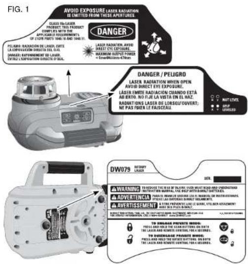
- For your convenience and safety, the following labels are on your laser (Fig. 1).
AVOID EXPOSURE: LASER RADIATION IS EMITTED FROM THIS APERTURES.
DANGER: LASER RADIATION. AVOID DIRECT EYE EXPOSURE.
Laser Information
The DW079 Cordless Rotary Laser is listed as a CLASS IIIA LASER PRODUCT and complies with the applicable requirement of title 21 of the Code of Federal Regulations set forth by: the Department of Health, Education, and Welfare; the Food and Drug Administration; the Center for Devices and Radiological Health.
These devices comply with Part 15 of the FCC Rules. Operation is subject to the following two conditions: (1) this device may not cause harmful interference, and (2) this device must accept any interference received, including interference that may cause undesired operation.
NOTE: This equipment has been tested and found to comply with the limits for a Class B digital device, pursuant to Part 15 of the FCC Rules. These limits are designed to provide reasonable protection against harmful interference in a residential installation. This equipment generates, uses and can radiate radio frequency energy and, if not installed and used in accordance with the instructions, may cause harmful interference to radio communications. However, there is no guarantee that interference will not occur in a particular installation. If this equipment does cause harmful interference to radio and television reception, which can be determined by turning the equipment off and on, the user is encouraged to try to correct the interference by one or more of the following measures:
• Reorient or relocate the receiving antenna.
- Increase the separation between the equipment and receiver.
- Connect the equipment into an outlet on a circuit differentfrom that which the receiver is connected.
- Consult the dealer or an experienced radio/TV technician for help.
These Class B digital devices comply with Canadian ICES-003.
| SPECIFICATIONS | |
| Light Source Semiconductor laser diode | |
| Laser Wavelength 630 - 680 nm Visible | |
| Laser Power <5mw, CLASS IIIa LASER PRODUCT | |
| Rotation Speed 0 - 600 rpm | |
| Self-Leveling Range ± 5° | |
| Indoor Visible Range 200' (61 m) diameter | |
| Range with Detector 1500' (450 m) diameter | |
| Level Accuracy ± 1/8" per 100' ( ± 3 mm per 31 m) | |
| Power Source | 9.6V-18V DEWALT batteries |
| Operating Temperature | 23°F to 122°F (-5°C to 50°C) |
| Storage Temperature | -4°F to 158°F (-20°C to 70°C) |
| Environmental | Water resistant |
Important Safety Instructions for All Battery Packs
When ordering replacement battery packs, be sure to include catalog number and voltage. Consult the chart at the end of this manual for compatibility of chargers and battery packs.
The battery pack is not fully charged out of the carton. Before using the battery pack and charger, read the safety instructions below. Then follow charging procedures outlined.
READ ALL INSTRUCTIONS
- Do not charge or use battery in explosive atmospheres, such as in the presence of flammable liquids, gases or dust.
Inserting or removing the battery from the charger may ignite the dust or fumes.
- NEVER force battery pack into charger. DO NOT modify battery pack in any way to fit into a non-compatible charger as battery pack may rupture causing serious personal injury. Consult the chart at the end of this manual for compatibility of batteries and chargers.
- Charge the battery packs only in DEWALT chargers.
• DO NOT splash or immerse in water or other liquids. - Do not store or use the tool and battery pack in locations where the temperature may reach or exceed 105°F (40") (such as outside sheds or metal buildings in summer).
▲DANGER: Electrocution hazard. Never attempt to open the battery pack for any reason. If battery pack case is cracked or damaged, do not insert into charger. Do not crush, drop or damage battery pack. Do not use a battery pack or charger that has received a sharp blow, been dropped, run over or damaged in any way (i.e., pierced with a nail, hit with a hammer, stepped on). Electric shock or electrocution may result. Damaged battery packs should be returned to service center for recycling.
NOTE: Battery storage and carrying caps are provided for use whenever the battery is out of the tool or charger. Remove cap before placing battery in charger or tool.
⚠ WARNING: Fire hazard. Do not store or carry battery so that metal objects can contact exposed battery terminals. For example, do not place battery in aprons, pockets, tool boxes, product kit boxes, drawers, etc., with loose nails, screws, keys, etc. without battery cap. Transporting batteries can possibly cause fires if the battery terminals inadvertently come in contact with conductive materials such as keys, coins, hand tools and the like. The US Department of Transportation Hazardous
Material Regulations (HMR) actually prohibit transporting batteries in commerce or on airplanes (i.e., packed in suitcases and carry-on luggage) UNLESS they are properly protected from short circuits. So when transporting individual batteries, make sure that the battery terminals are protected and well insulated from materials that could contact them and cause a short circuit.
SPECIFIC SAFETY INSTRUCTIONS FOR NICKEL CADMIUM (NICd) OR NICKEL METAL HYDRIDE (NIMH)
- Do not incinerate the battery pack even if it is severely damaged or is completely worn out. The battery pack can explode in a fire.
- A small leakage of liquid from the battery pack cells may occur under extreme usage or temperature conditions. This does not indicate a failure.
However, if the outer seal is broken:
a. and the battery liquid gets on your skin, immediately wash with soap and water for several minutes.
b. and the battery liquid gets into your eyes, flush them with clean water for a minimum of 10 minutes and seek immediate medical attention. (Medical note: The liquid is 25-35% solution of potassium hydroxide.)
SPECIFIC SAFETY INSTRUCTIONS FOR LITHIUM ION (LI-ION)
- Do not incinerate the battery pack even if it is severely damaged or is completely worn out. The battery pack can explode in a fire. Toxic fumes and materials are created when lithium ion battery packs are burned.
- If battery contents come into contact with the skin, immediately wash area with mild soap and water. If battery liquid gets into the eye, rinse water over the open eye for 15 minutes or until irritation ceases. If medical attention is needed, the battery electrolyte is composed of a mixture of liquid organic carbonates and lithium salts.
- Contents of opened battery cells may cause respiratory irritation. Provide fresh air. If symptoms persist, seek medical attention.
⚠ WARNING: Burn hazard. Battery liquid may be flammable if exposed to spark or flame.
The RBRC™ Seal
The RBRC™ (Rechargeable Battery Recycling Corporation) Seal on the nickel cadmium, nickel metal hydride or lithium ion batteries (or battery packs) indicate that the costs to recycle these batteries (or battery packs) at the end of their useful life have already been paid by DEWALT. In some areas, it is illegal to place spent nickel cadmium, nickel metal hydride or lithium ion batteries in the trash or municipal solid waste stream and the RBRC program provides an environmentally conscious alternative. RBRC™ in cooperation with DEWALT and other battery users, has established programs in the United States and Canada to facilitate the collection of spent nickel cadmium, nickel metal hydride or lithium ion batteries. Help protect our environment and conserve natural resources by returning the spent nickel cadmium and nickel cadmium, nickel metal hydride or lithium ion batteries to an authorized DEWALT service center or to your local retailer for recycling. You may also contact your local recycling center for information on where to drop off the spent battery. RBRC™ is a registered trademark of the Rechargeable Battery Recycling Corporation.
Important Safety Instructions for All Battery Chargers
SAVE THESE INSTRUCTIONS: This manual contains important safety and operating instructions for battery chargers.
- Before using charger, read all instructions and cautionary markings on charger, battery pack, and product using battery pack.
▲ DANGER: Electrocution hazard. 120 volts are present at charging terminals. Do not probe with conductive objects. Electric shock or electrocution may result.
▲WARNING: Shock hazard. Do not allow any liquid to get inside charger. Electric shock may result.
CAUTION: Burn hazard. To reduce the risk of injury, charge only DEWALT rechargeable batteries. Other types of batteries may burst causing personal injury and damage.
CAUTION: Under certain conditions, with the charger plugged in to the power supply, the exposed charging contacts inside the charger can be shorted by foreign material. Foreign materials of a conductive nature such as, but not limited to, steel wool, aluminum foil, or any buildup of metallic particles should be kept away from charger cavities. Always unplug the charger from the power supply when there is no battery pack in the cavity. Unplug charger before attempting to clean. - DO NOT attempt to charge the battery pack with any chargers other than the ones in this manual. The charger and battery pack are specifically designed to work together.
• These chargers are not intended for any uses other than charging DEWALT rechargeable batteries. Any other uses may result in risk of fire, electric shock or electrocution. - Do not expose charger to rain or snow.
- Pull by plug rather than cord when disconnecting charger. This will reduce risk of damage to electric plug and cord.
-
Make sure that cord is located so that it will not be stepped on, tripped over, or otherwise subjected to damage or stress.
-
Do not use an extension cord unless it is absolutely necessary. Use of improper extension cord could result in risk of fire, electric shock, or electrocution.
- When operating a power tool outdoors, use an extension cord suitable for outdoor use. Use of a cord suitable for outdoor use reduces the risk of electric shock.
- An extension cord must have adequate wire size (AWG or American Wire Gauge) for safety. The smaller the gauge number of the wire, the greater the capacity of the cable, that is 16 gauge has more capacity than 18 gauge. An undersized cord will cause a drop in line voltage resulting in loss of power and overheating. When using more than one extension to make up the total length, be sure each individual extension contains at least the minimum wire size. The following table shows the correct size to use depending on cord length and nameplate ampere rating. If in doubt, use the next heavier gauge. The smaller the gauge number, the heavier the cord.
Recommended Minimum Wire Size for Extension Cords tal Length of Cord
| 25 ft. | 50 ft. | 75 ft. | 100 ft. | 125 ft. | 150 ft. | 175 ft. |
| 7.6 m | 15.2 m | 22.9 m | 30.5 m | 38.1 m | 45.7 m | 53.3 m |
Wire Size AWG
| 18 | 18 | 16 | 16 | 14 | 14 | 12 |
- Do not place any object on top of charger or place the charger on a soft surface that might block the ventilation slots and result in excessive internal heat. Place the charger in a position away from any heat source. The charger is ventilated through slots in the top and the bottom of the housing.
-
Do not operate charger with damaged cord or plug.
-
Do not operate charger if it has received a sharp blow, been dropped, or otherwise damaged in any way. Take it to an authorized service center.
- Do not disassemble charger; take it to an authorized service center when service or repair is required. Incorrect reassembly may result in a risk of electric shock, electrocution or fire.
- Disconnect the charger from the outlet before attempting any cleaning. This will reduce the risk of electric shock. Removing the battery pack will not reduce this risk.
- NEVER attempt to connect 2 chargers together.
- The charger is designed to operate on standard 120V household electrical power. Do not attempt to use it on any other voltage. This does not apply to the vehicular charger.
Using Automatic Tune-Up™ Mode
The Automatic Tune-Up™ Mode equalizes or balances the individual cells in the battery pack allowing it to function at peak capacity. Battery packs should be tuned up weekly or after 10 charge/discharge cycles or whenever the pack no longer delivers the same amount of work. To use the Automatic Tune-Up™, place the battery pack in the charger and leave it for at least 8 hours. The charger will cycle through the following modes.
- The red light will blink continuously indicating that the 1-hour charge cycle has started.
- When the 1-hour charge cycle is complete, the light will stay on continuously and will no longer blink. This indicates that the pack is fully charged and can be used at this time.
-
If the pack is left in the charger after the initial 1-hour charge, the charger will begin the Automatic Tune-Up™ mode. This mode continues up to 8 hours or until the individual cells in the battery pack are equalized. The battery pack is ready for use and can be removed at any time during the Automatic Tune-Up™ mode.
-
Once the Automatic Tune Up™ mode is complete, the charger will begin a maintenance charge; the red indicator will remain lit.
Chargers
Your tool uses a DEWALT 9.6, 12, 14.4, 18 Volt charger. Be sure to read all safety instructions before using your charger. Consult the chart at the end of this manual for compatibility of chargers and battery packs.
Charging Procedure
▲DANGER: Electrocution hazard. 120 volts present at charging terminals. Do not probe with conductive objects. Danger of electric shock or electrocution.
- Plug the charger into an appropriate outlet before inserting battery pack.
- Insert the battery pack into the charger, making sure the pack is fully seated. The red (charging) light will blink continuously indicating that the charging process has started.
- The completion of charge will be indicated by the red light remaining ON continuously. The pack is fully charged and may be used at this time or left in the charger.
Indicator Light Operation

Charge Indicators
Some chargers are designed to detect certain problems that can arise with battery packs. Problems are indicated by the red light flashing at a fast rate. If this occurs, re-insert battery pack into the charger. If the problem persists, try a different battery pack to determine if the charger is OK. If the new pack charges correctly, then the original pack is defective and should be returned to a service center or other collection site for recycling. If the new battery pack elicits the same trouble indication as the original, have the charger tested at an authorized service center.
HOT/COLD PACK DELAY
Some chargers have a Hot/Cold Pack Delay feature: when the charger detects a battery that is hot, it automatically starts a Hot Pack Delay, suspending charging until the battery has cooled. After the battery has cooled, the charger automatically switches to the Pack Charging mode. This feature ensures maximum battery life. The red light flashes long, then short while in the Hot Pack Delay mode.
PROBLEM POWER LINE
Some chargers have a Problem Power Line indicator. When the charger is used with some portable power sources such as generators or sources that convert DC to AC, the charger may temporarily suspend operation, flashing the red light with two fast blinks followed by a pause. This indicates the power source is out of limits.
LEAVING THE BATTERY PACK IN THE CHARGER
The charger and battery pack can be left connected with the red light glowing indefinitely. The charger will keep the battery pack fresh and fully charged.
NOTE: A battery pack will slowly lose its charge when kept out of the charger. If the battery pack has not been kept on maintenance charge, it may need to be recharged before use. A battery pack may also slowly lose its charge if left in a charger that is not plugged into an appropriate AC source.
WEAK BATTERY PACKS: Chargers can also detect a weak battery pack. Such batteries are still usable but should not be expected to perform as much work. The charger will indicate to replace battery pack.
Important Charging Notes
- Longest life and best performance can be obtained if the battery pack is charged when the air temperature is between 65^ F and 75^ F ( 18^ - 24^ C). DO NOT charge the battery pack in an air temperature below +40^ F (+ 4.5^ C), or above +105^ F (+ 40.5^ C). This is important and will prevent serious damage to the battery pack.
- The charger and battery pack may become warm to touch while charging. This is a normal condition, and does not indicate a problem. To facilitate the cooling of the battery pack after use, avoid placing the charger or battery pack in a warm environment such as in a metal shed, or an uninsulated trailer.
- If the battery pack does not charge properly:
a. Check current at receptacle by plugging in a lamp or other appliance
b. Check to see if receptacle is connected to a light switch which turns power off when you turn out the lights.
c. Move charger and battery pack to a location where the surrounding air temperature is approximately 65^ F - 75^ F ( 18^ - 24^ C).
d. If charging problems persist, take the tool, battery pack and charger to your local service center.
- The battery pack should be recharged when it fails to produce sufficient power on jobs which were easily done previously. DO NOT CONTINUE to use under these conditions. Follow
the charging procedure. You may also charge a partially used pack whenever you desire with no adverse affect on the battery pack.
-
Under certain conditions, with the charger plugged into the power supply, the exposed charging contacts inside the charger can be shorted by foreign material. Foreign materials of a conductive nature such as, but not limited to, steel wool, aluminum foil, or any buildup of metallic particles should be kept away from charger cavities. Always unplug the charger from the power supply when there is no battery pack in the cavity. Unplug charger before attempting to clean.
-
Do not freeze or immerse charger in water or any other liquid.
WARNING: Shock hazard. Don't allow any liquid to get inside charger. Electric shock may result.
⚠️CAUTION: Never attempt to open the battery pack for any reason. If the plastic housing of the battery pack breaks or cracks, return to a service center for recycling.
Storage Recommendations
-
The best storage place is one that is cool and dry away from direct sunlight and excess heat or cold.
-
Long storage will not harm the battery pack or charger. Under proper conditions, they can be stored for 5 years or more.
SAVE THESE INSTRUCTIONS FOR FUTURE USE
LASER OPERATION
- To extend battery life per charge, turn the laser off when it is not in use.
-
To ensure the accuracy of your work, check the laser calibration often. Refer to Field Calibration Check under Laser Maintenance.
-
Before attempting to use the laser, make sure the tool is positioned on a relatively smooth, secure surface.
- Always mark the center of the laser line or dot. If you mark different parts of the beam at different times you will introduce error into your measurements.
- To increase working distance and accuracy, set up the laser in the middle of your working area.
- When attaching to a tripod or wall, mount the laser securely.
- When working indoors, a slow rotary head speed will produce a visibly brighter line, a faster rotary head speed will produce a visibly solid line.
- To increase beam visibility, wear Laser Enhancement Glass es and/or use a Laser Target Card to help find the beam.
- Extreme temperature changes can cause movement or shifting of building structures, metal tripods, equipment, etc., which can effect accuracy. Check your accuracy often while working.
- When working with the D EWALT Digital Laser Detector, set the laser's rotation speed to the fastest setting.
- If the laser is dropped or has suffers a sharp blow, have the calibration system checked by a qualified service center before using the laser.
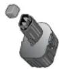
Installing and Removing the Battery Pack (Fig. 2)
NOTE: Make sure your battery pack is fully charged before you install it.
INSTALLING THE BATTERY PACK
- Release latch (B) to open the hatch door (A). Insert the battery pack (C).
CAUTION: The laser will operate even if battery door is not fully latched. To secure the battery, always ensure battery door is closed and latched.
- Slide the battery pack in firmly.
- Close the hatch door and fasten latch.
REMOVING THE BATTERY PACK
- Release latch to open the hatch door.
- Remove the battery pack.
- To recharge the battery pack, insert it into the charger as described in the charger section of this manual.
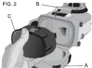
Laser Control Panel
The laser is controlled by the power button (D), the speed/rotation button (E), the scan mode button (F), and two arrows (G, H). The arrows control the movement of the laser head left and right when the laser is being used in the plumb mode. Four LED indicator lights are on the control panel: power (I), X-axis leveling (J), Y-axis leveling (K) and remote control private mode (L).
TURNING THE LASER ON (FIG. 3)
- Insert the fully charged battery pack. Be sure that the battery door is securely latched.
- Gently press the power button (D) to power the laser on. The power LED indicator light (J) will illuminate. If the laser is out of
level, the X-axis (J) and/or Y-axis (K) leveling lights will flash until the laser is level. Press the speed/rotation button (E) to adjust the rotation speed.
NOTE: The head will begin or resume rotation once the laser is level.
TURNING THE LASER OFF
Gently press the power button to turn the laser off. The power LED indicator light will no longer be illuminated.
Laser Control Panel Buttons
POWER BUTTON
To completely power the laser unit off, the power button on the control panel of the laser unit must be pressed. The laser unit will also automatically power off if it is left in Sleep Mode for 8 hours.
NOTE: Press the remote control power button to put the laser unit into Sleep Mode. In Sleep Mode all laser unit functions shut off except for a periodic blink from the power LED on the control panel of the laser unit. Press the remote control power button again to "wake up" the laser unit.
ARROW BUTTONS
The arrow buttons (G, H) are used for different functions depending on the operating mode of the laser unit.
In Self-Leveling Horizontal Mode:
The arrows buttons adjust the direction of the laser beam in Scan Mode or Pointing Mode (0 rpm).
In Self-Leveling Vertical Mode:
The arrow buttons move the laser beam left and right.
In Manual Mode:
The arrow buttons are used to tilt the laser head.
NOTE: Refer to Using the Wireless Remote Control for a full description of Manual Mode.
SPEED/ROTATION BUTTON
The speed/rotation button (E) is used to adjust the rotation speed of the laser beam through its 4 preset speeds.
The head speed will cycle through 4 speeds, then repeat the sequence as the speed/rotation button is pressed.
REMEMBER:
Slow speed = Bright Beam Fast Speed = Solid Beam
NOTE: The speed/rotation button performs the same function as the speed/rotation button on the remote control.
SCAN MODE BUTTON
The scan mode button (F) is used to make the laser head sweep back and forth, creating a short, bright laser line. This short line is much brighter and more visible than when the unit is in full rotation mode.
Using Scan Mode:
To enter Scan Mode, push and release the scan mode button. To exit Scan Mode, push and release the button again.
The size and direction of the scan zone can be controlled with the arrow buttons on the laser unit control panel or the remote control. For a more detailed explanation, refer to Using the Wireless Remote Control.
The size and direction of the scan zone can also be controlled manually with the User Defined Scan Mode:
-
Set the laser unit at 0 rpm (pointer mode).
-
Manually rotate the laser head to position the laser beam at one edge of the desired scan zone.
-
Press and hold the scan mode button on the laser unit control panel. While holding down the scan mode button, manually rotate the laser head to the opposite edge of the desired scan zone.
-
Release the scan mode button.
-
The laser will scan between the two selected points.
NOTE: If the scan mode button is pressed and held, but the laser head is not manually rotated, after four seconds the unit will enter Private Mode or No Remote Mode as described below.
IMPORTANT: The remote control cannot be used for User Defined Scan Mode.
PUBLIC, PRIVATE AND NO REMOTE MODES
The DW079 Rotary Laser and the DW0794 Remote Control each have the capability to operate in either Public Mode or Private Mode. For the laser and the remote control to work together, they must both be set to the same mode. The laser unit can also be set to No Remote Mode, which causes it to ignore all remote control commands.
Public Mode
The laser unit can receive commands from any DEWALT laser remote control, and even from some other brands of
laser remote controls. This is the normal, default operating mode for the DW079 laser unit.
To activate Public Mode:
• After being fully powered off, the laser unit will power in Public Mode.
OR
- Press and hold the speed/rotation button (E) (op padlock symbol beside the button).
Private Mode
The laser unit will only accept commands from the DW0794 remote control designated by the user.
To activate Private Mode:
- Press and hold the scan mode button (F) on the last unit control panel (closed padlock symbol) and at the same time press and hold the remote control scan mode button (R) (closed padlock symbol).
After 4 seconds, both the laser unit and the remote control will enter Private Mode. As confirmation, the laser unit will beep and the laser control panel LED (L) (next to the closed padlock symbol) and the remote control LED (T) (next to the closed padlock symbol) will flash.
No Remote Mode
This mode causes the laser unit to ignore all rem control commands.
To activate No Remote Mode:
- Press and hold the scan mode button (F) on the last unit control panel (closed padlock symbol), but do not press any button on the remote control.
After 4 seconds, the laser unit will beep and the LED (L) next to the padlock symbol will flash.
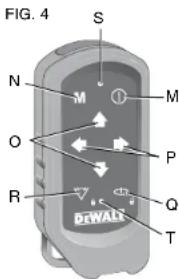
Using the Wireless Remote Control (Fig. 4)
The remote control allows one person to operate and setup the laser from a distance. The remote control features a power button (M), manual mode button (N), four arrows (O, PP), speed/rotation button (Q) and scan mode button (R). Two LED indicator lights are on the remote control: transmit (S) and private mode (T).
REMOTE CONTROL: POWER BUTTON
Press the remote control power button (M) to put the laser unit into Sleep Mode. In Sleep Mode all laser unit
functions shut off except for a periodic blink from the power LED (L) on the control panel of the laser unit. Press the remote control power button again to "wake up" the laser unit.
NOTE: To completely power the laser unit off, the power button on the control panel of the laser unit must be pressed. The laser unit will also automatically power off if it is left in Sleep Mode for 8 hours.
REMOTE CONTROL: MANUAL MODE BUTTON M
To activate Manual Mode, press and hold the remote control manual mode button (N) for 3 seconds. Manual Mode must be activated to use manual sloping. (Refer to Using Manual Slope Mode for a ser Complete description of this function.)
To re-engage full self-leveling, press and hold the manual mode button again for 3 seconds.
Using Manual Slope Mode:
The DW079 Manual Slope Mode allows the self-leveling function to be disabled in one axis (direction) so that the laser can be sloped in that axis. The other axis will continue to self-level, ensuring that the laser beam is only sloping in the expected direction.
Entering and exiting Manual Slope Mode:
• To activate Manual Slope Mode, press and hold the remote control manual mode button (N) for 3 seconds.
• To re-engage full self-leveling, press and hold the manual mode button again for 3 seconds.
Setting the Slope Direction:
- When Manual Slope Mode is activated, the unit automatically engages Manual Y Mode. This allows the operator to slope the laser in the direction of the Y-axis, as indicated by the "gunsights" on the rollcage.
In certain situations, it may be desirable to slope the laser in the X-axis. The direction of Manual Slope Mode can be changed back and forth between the Y- and X-axes as follows:
- Immediately (within 5 seconds) after entering Manual Slope Mode, press and hold the remote control right arrow button to activate Manual X Mode.
- The unit can be changed back to Manual Y Mode by immediately pressing and holding the remote control left arrow button.
• To change the direction of Manual Slope Mode at a later time, re-engage full self-leveling, then activate Manual Slope Mode again and go through the axis selection procedure outlined above.
The X and Y LED indicator lights on the laser unit control panel (Fig. 3, K, J) will indicate the manual slope direction
that is selected. The manually controlled axis is identified by a turned-off LED, and the self-leveling axis is identified by a lighted LED.
Setting the Amount of Slope:
Once Manual Slope Mode is activated, the amount of slope can be manually adjusted using any of the following methods:
OR
OR
• Use the laser control panel up and down arrow buttons (Fig. 3, G, H) to tilt the laser rotor head up and down.
• Use the remote control up and down arrow buttons (Fig. 3, O) to tilt the laser rotor head up and down.
- The entire laser unit can be tipped up and down by setting it on a sloped surface. Make sure the laser unit is positioned so the direction of manual sloping is lined up in the same direction as the sloped surface.
REMOTE CONTROL: ARROW BUTTONS
The arrow buttons (O, P) are used for different functions depending on the operating mode of the laser unit.
In Self-Leveling Horizontal Mode
The up and down arrows (O) adjust the length of the laser line in Scan Mode.
The left and right arrows (P) adjust the direction of the laser beam in Scan Mode or Pointing Mode (0 rpm).
In Self-Leveling Vertical Mode:
The up and down arrows (O) adjust the position of the laser line in Scan Mode.
The left and right arrows (P) move the laser beam left and right.
In Manual Mode:
The arrow buttons (O) are used to tilt the laser head up or down in the X or Y directions as marked on the protective roll cage of the laser unit.
REMOTE CONTROL: SPEED/ROTATION BUTTON
The speed/rotation button (Q) is used to adjust the speed of the laser beam through its 4 preset speeds.
NOTE: The speed/rotation button performs the same function as the speed/rotation button on the control panel of the laser unit.
REMOTE CONTROL: SCAN MODE BUTTON
The scan mode button (R) is used to make the laser head sweep back and forth, creating a short, bright laser line. This short line is much brighter and more visible than when the unit is in full rotation mode.
Using Scan Mode:
To enter Scan Mode, push and release the scan mode button. To exit Scan Mode, push and release the button again.
The size and direction of the scan zone can be controlled with the arrow buttons on the laser unit control panel or the remote control. For a more detailed explanation, refer to Arrow Buttons under Laser Control Panel Buttons.
IMPORTANT: The remote control cannot be used for User Defined Scan Mode.
REMOTE CONTROL: PUBLIC AND PRIVATE MODE
The DW079 Rotary Laser and the DW0794 Remote Control each have the capability to operate in either Public Mode or Private Mode. For the laser and the remote control to work together, they must both be set to the same mode.
Public
Mode
The remote control sends signals that can potentially be received by multiple laser units as well as other models of
laser units. This is the normal, default operating mode for the DW0794 remote control.
To activate Public Mode:
- Press and hold the speed/rotation button (Q) (open padlock symbol beside the button) for 4 seconds.
• After an 8-hour period of inactivity, the remote control will automatically enter Public Mode. - After replacement of its battery, the remote control will automatically enter Public Mode.
Private Mode
The remote control sends signals that can only be received by the designated laser unit.
To activate Private Mode:
- Press and hold the remote control scan mode button (R) (closed padlock symbol beside the button) and at the same time, press and hold the scan mode button (F) on the laser unit control panel (closed padlock symbol).
After 4 seconds, both the remote control and the laser unit will enter Private Mode. As confirmation, the laser unit will beep and the laser unit control panel LED (L) (next to the closed padlock symbol) and the remote control LED (T) (next to the closed padlock symbol) will flash.
Height of Instrument Alert
The DW079 has a built-in alarm feature that alerts the operator if the unit is disturbed after the unit has self-leveled. The laser unit will stop rotating, the control panel LED indicator lights will flash and the beeper will sound.
TO RESET THE LASER UNIT FOR CONTINUED USE
- Turn the unit off and back on again using the power button on the laser unit control panel.
- Put the unit in sleep mode and then wake it back up using the power button on the remote control.
OR
NOTE: Always recheck the laser setup after the Height of Instrument Alert has triggered.
Laser Troubleshooting
LASER AND REMOTE CONTROL ARE OUT OF SYNC
- On the remote control, press and hold speed/rotation button for 4 seconds to activate Public Mode.
- On the laser unit, press and hold speed/rotation button for 4 seconds to activate Public Mode.
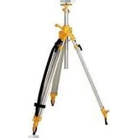
Using the Laser on a Tripod
- Position the tripod securely and set it to the desired height.
- Make sure that the top of the tripod is roughly level. The laser will self-level only if the top of the tripod is within ±5' of level. If the laser is set up too far out of level, it will beep when it reaches the limit of its leveling range. No damage will be done to the laser, but it will not operate in an "out of level" condition.
- Secure the laser to the tripod by screwing the threaded knob on the tripod into the female thread on the bottom of the laser.
NOTE: Be sure that the tripod you are working with has a 5/8"-11 threaded screw to ensure secure mounting. - Turn the laser on and adjust the rotation speed and controls as desired.
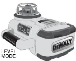
Using the Laser on a Floor (Fig. 5)
The laser level can be positioned directly on the floor for leveling and plumbing applications such as framing walls.
- Place the laser on a relatively smooth and level surface where it will not be disturbed.
- Position the laser for a level or plumb setting as shown.
- Turn the laser on and adjust the rotation speed and controls as desired.
FIG. 5
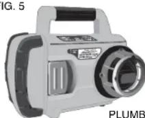
PLUMB MODE
natural_image
Exterior view of a DeWALT brand electric shaver with control panel (no text or symbols on the device itself)NOTE: The laser will be easier to set up for wall applications if the rotation speed is set to 0 rpms and if the remote control is used to line up the laser with control marks. The remote allows one person to set up the laser.
Manual Head Rotation
The laser is designed with a protective alloy cage around the rotary head to prevent accidental damage from work site activities. You can still access the rotary head and manually direct the beam to establish or transfer a mark.
Laser Accessories
Recommended accessories for use with your tool are available for purchase at your factory-owned local service center.
⚠ WARNING: Since accessories, other than those offered by DEWALT, have not been tested with this product, use of such accessories with this tool could be hazardous. To reduce the risk of injury, only DEWALT, recommended accessories should be used with this product.
If you need assistance in locating any accessory, please contact DEWALT Industrial Tool Co., 701 East Joppa Road, Baltimore, MD 21286, call 1-800-4-DEWALT (1-800-433-9258) or visit our website www.dewalt.com
Laser Enhancement Glasses
Some laser kits include a pair of Laser En hancement Glasses (Fig. 6). These red lens glasses improve the visibility of the laser beam under bright light conditions or over long distances when the laser is used for interior applications. These glasses are not required to operate the laser.
FIG. 6
CAUTION: These glasses are not ANSI approved safety glasses and should not be worn while operating other tools. These glasses do not keep the laser beam from entering your eyes.
ADANGER: TO REDUCE THE RISK OF SERIOUS PERSONAL INJURY, NEVER STARE DIRECTLY INTO THE LASER BEAM, WITH OR WITHOUT THESE GLASSES.
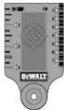
Target Card
Some laser kits include a Laser Target Card (Fig. 7) to aid in locating and marking the laser beam. The target card enhances the visibility of the laser beam as the beam crosses over the card. The card is
marked with standard and metric scales. The laser beam passes through the red plastic and reflects off of the reflective tape on the reverse side. The magnet at the top of the card is designed to hold the target card to ceiling track or steel studs to determine plumb and level positions. For best performance when using the Target Card, the DEWALT logo should be facing you.
FIG. 7
Digital Laser Detector: DW0772 (Fig. 8-10)
Some laser kits include a DEWALT Digital Laser Detector. The DEWALT Digital Laser Detector allows you to locate a laser beam emitted by a rotary laser in bright light conditions or over long distances. The detector can be used in both indoor and outdoor situations where it is difficult to see the laser beam.
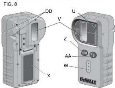
The detector is not for use with non-rotating lasers but is compatible with most rotary red-beam or infrared (invisible) beam lasers on the market. It can be set to indicate the location of the beam to either the nearest 1/8" (3 mm) or the nearest 1/25" (1 mm). The detector gives both visual signals through the display window (V) and audio signals through the speaker (W) to indicate the location of the laser beam.
The DEWALT Digital Laser Detector can be used with or without the detector clamp. When used with the clamp, the detector can be positioned on a grade rod, leveling pole, stud or post.
BATTERIES (FIG. 9)
The Digital Laser Detector is powered by a 9 volt battery. To install the battery provided, lift up on the battery compartment cover (X). Place the 9 volt battery in the compartment, aligning the battery as shown on the embossed icon (Y).
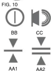
DETECTOR CONTROLS (FIG. 10)
The detector is controlled by the power/volume button (Z) and the accuracy mode button (AA).
When the power/volume button is pushed once, the detector is turned on. The top of the display window shows the ON icon (BB), and the volume icon (CC). To decrease the volume of the audible signal that the detector emits when it senses a laser beam, push the button again; one of the half circles next to the horn icon will disappear. To turn off the audible signal push the button a third time; the volume icon will dissapear. The DEWALT Digital
Laser Detector also has an auto shut-off feature. If a rotary laser beam does not strike the beam detection window, or if no buttons are pressed, the detector will shut itself off in about 30 minutes.
When the detector is on, the bottom of the window shows an accuracy mode icon. Either the ±1/25" (1 mm) accuracy mode icon (AA1) will appear, or the ±1/8" (3 mm) accuracy mode icon (AA2) will appear. When the ±1/25" (1 mm) accuracy mode icon appears, it indicates that the detector will give an "on grade" reading only when the laser beam is on grade or no more than 1/25" (1 mm) above or below it. When the 1/8" (3 mm) accuracy mode icon appears, it indicates that the detector will give an "on grade" reading when the laser beam is on grade or approximately 1/8" (3 mm) above or below it. Push the accuracy mode button (AA) once to change the accuracy mode.
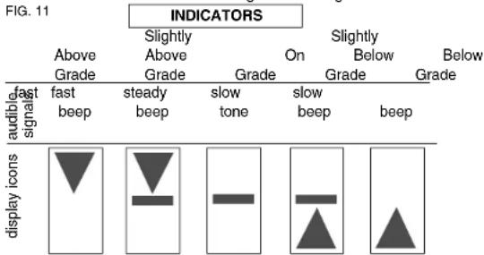
Detector Operation (Fig. 11)
- Set up and position the rotary laser that you will be using according to the manufacturer's directions. Tum the laser on and make sure that the laser is rotating and emitting a laser beam.
NOTE: This detector has been designed to be used only with a rotating laser. The detector will not work with a stationary beam laser level.
- Turn the detector on by pressing the power/volume button (Z).
- Adjust the volume as desired as described in the Detector Controls.
- Position the detector so that the detector window (U) is facing the laser beam produced by the rotary laser. Move the detector up or down within the approximate area of the beam, until you have centered the detector. For information about the display window indicators and the audible signal indicators, refer to the table titled Indicators (Fig. 11).
- Use the marking notches (DD) to accurately mark the position of the laser beam.
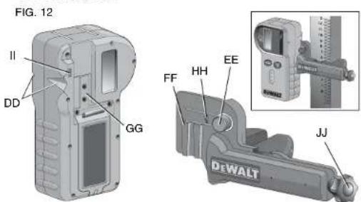
MOUNTING ON A GRADE ROD (FIG. 12)
- To secure your detector to a grade rod, first attach the detector to the clamp by pushing in on the clamp latch (EE). Slide the
tracks (FF) on the clamp around the rail (GG) on the detector until the latch (HH) on the clamp pops into the latch hole (II) on the detector.
- Open the jaws of the clamp by turning the clamp knob (JJ) counterclockwise.
- Position the detector at the height needed and turn the clamp knob clockwise to secure the clamp on the rod.
- To make adjustments in height, slightly loosen the clamp, reposition and retighten.
Detector Cleaning and Storage
- Dirt and grease may be removed from the exterior of the detector using a cloth or soft, non-metallic brush.
- The EWALT Digital Laser Detector is waterproof. If you should drop the detector in mud, wet concrete, or a similar substance, simply hose the detector off. Do not use high pressure water, e.g., from a pressure washer.
- The best storage place is one that is cool and dry-away from direct sunlight and excess heat or cold.
Detector Service
Except for batteries, there are no user serviceable parts in the Digital Laser Detector. Do not disassemble the unit. Unauth orized tampering with the laser detector will void all warranties.
Detector Troubleshooting
THE DETECTOR WILL NOT TURN ON.
- Press and release the power/volume button.
- Check to see that the battery is in place and in the proper position.
- If the detector is very cold, allow it to warm up in a heated area.
- Replace the 9 volt battery. Turn the unit on.
- If the detector still does not turn on, take the detector to a DEWALT service center.
THE DETECTOR'S SPEAKER MAKES NO SOUND.
- Ensure that the detector is on.
- Press the power/volume button. It will toggle from high, to low, to mute.
- Ensure that the rotary laser is spinning and that it is emitting a laser beam.
- If the detector is still not making any sound, take it to a DEWALT service center.
THE DETECTOR DOES NOT RESPOND TO A STATIONARY LASER BEAM.
- The BWALT Digital Laser Detector has been designed to work only with rotary lasers.
THE DETECTOR GIVES OFF A TONE BUT THE LCD DISPLAY WINDOW DOES NOT FUNCTION.
- If the detector is very cold, allow it to warm up in a heated area.
- If the LCD display window is still not functioning, take the detector to a DEWALT service center.
Construction Grade Rod
▲DANGER: NEVER attempt to use a grade rod in a storm or near overhanging electric wires. Death or serious personal injury will occur.
Some laser kits include a grade rod. The DEWALT Grade Rod is marked with measurement scales on both sides and is constructed in telescoping sections. A spring-loaded button actuates a lock to hold the grade rod at various lengths.
The front of the grade rod has the measurement scale starting at the bottom. Use this for measuring from the ground up when grading or leveling jobs.
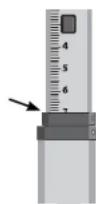
The back of the grade rod is designed to measure the height of ceilings, joists, etc. Fully extend the top section of the grade rod until the button locks into the previous section. Extend that section either until it locks into the adjacent section or until the grade rod touches the ceiling or joist. The height is read where the last extended section exits the previous lower section, as shown in Figure 13.
FIG. 13
Using the Laser with a Wall Mount (Fig. 14, 15)
Some laser kits include a Wall Mount. It can be used for attaching the tool to track or ceiling angle and to aid in acoustical ceiling installation. Follow the directions below for using the wall mount.
CAUTION: Before attaching the laser level to wall track or ceiling angle, be sure that the track or angle is properly secured.
- Place the laser on the mounting base (KK) aligning the hole (LL) on the bottom of the laser with the hole (MM) in the mounting base. Turn the mounting knob (NN) to secure the laser.
- With the wall mount measuring scale (OO) facing you, loosen the wall mount clamp locking knob (PP) to open the clamp jaws.
- Position the clamp jaws around the wall track or ceiling angle and tighten the wall mount clamp locking knob (PP) to close the clamp jaws onto the track. Be sure that the wall mount clamp locking knob is securely tightened before proceeding.
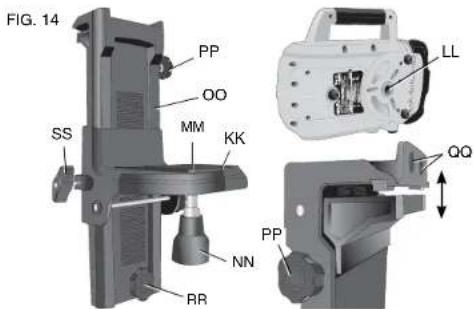
ACAUTION: Always use a ceiling wire hanger or equivalent material, in addition to the wall mount clamp locking knob, to help secure the laser level while mounting it to a wall. Thread the wire through the handle of the laser level. DO NOT thread the wire through the protective metal cage. Additionally, screws may be used to fasten the wall mount directly to the wall as a back. FIG. 15 SS directly to the wall as a back up. Screw holes (QQ) are located at the top of the wall mount.
-
Using the base leveling knob (RR) approximate a level position from the wall.
-
The tool can be adjusted up and down to the desired
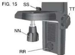
offset height for working. To change the height, loosen the locking knob (SS) located on the left of the wall mount. Support the mounting base when adjusting the height.
- Turn the adjustment knob (TT), located to the right of the wall mount, to move the laser level up and down to set your height. Use the wall mount measuring scale (OO) to pinpoint your mark.
NOTE: It may be helpful to turn the power on and turn the rotary head so that it puts a dot on one of the laser scales. The DEWALT target card is marked at 1-1/2" (38 mm), therefore, it may be easiest to set the offset of the laser to 1-1/2" (38 mm) below the track.
- Once you have positioned the laser at the desired height, tighten the locking knob (SS) to maintain this position.
LASER MAINTENANCE
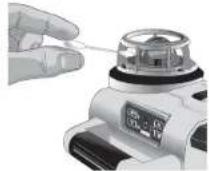
- Under some conditions, the glass lens inside the rotary head may collect some dirt or debris. This will affect beam quality and operating range. The lens should be cleaned with a cotton swab moistened with water as shown in Figure 16.
- The flexible rubber shield can be cleaned with a wet lint-free cloth such as a cotton cloth. USE WAT cleansers or solvents. Allow the ur
- To maintain the accuracy of your work, check the calibration of the laser often. Refer to Field Calibration Check.
- Calibration checks and other maintenance repairs can be performed by DEWALT service centers. Two free calibration checks are included under the DEWALT One Year Free Service Contract.
- When the laser is not in use, store it in the kit box provided.
- Do not store your laser in the kit box if the laser is wet. Dry exterior parts with a soft, dry cloth and allow the laser to air dry.
- Do not store your laser at temperatures below 0°F (-18°C) or above 105°F (41°C).
▲WARNING: Never use solvents or other harsh chemicals for cleaning the non-metallic parts of the tool. These chemicals may weaken the materials used in these parts. Use a cloth dampened only with water and mild soap. Never let any liquid get inside the unit; never immerse any part of the unit into a liquid. Never use compressed air to clean the laser.
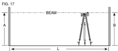
Field Calibration Check (Fig. 17, 18)
Field calibration checks should be done frequently. This section provides instructions for performing simple field calibration checks of your DEWALT Rotary Laser. Field calibration checks do not calibrate the laser. That is, these checks do not correct errors in the leveling or plumbing capability of the laser. Instead, the checks indicate whether or not the laser is providing a correct level and plumb line. These checks cannot take the place of professional calibration performed by a DEWALT service center.
LEVEL CALIBRATION CHECK (X-AXIS)
- Set up a tripod between two walls that are at least 50 feet apart. The exact location of the tripod is not critical.
- Mount the laser unit on the tripod so that the X-axis points directly toward one of the walls.
- Turn the laser unit on and allow it to self-level.
- Mark and measure points A and B on the walls as shown in Figure 17.
- Turn the entire laser unit 180^ so the X-axis points directly toward the opposite wall.
- Allow the laser unit to self-level, and mark and measure points AA and BB on the walls as shown in Figure 18.
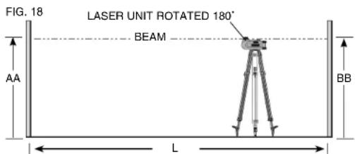
- Calculate the total error using the equation:
Total Error = (AA - A) - (BB - B)
- Compare total error to the allowable limits shown in the following table.
| Distance between walls | Allowable Error |
| L = 50 ft. (15.3 m) 1/8" | (3 mm) |
| L = 75 ft. (22.9 m) 3/16" | (4.5 mm) |
| L = 100 ft. (30.5 m) 1/4" | (6 mm) |
LEVEL CALIBRATION CHECK (Y-AXIS)
Repeat the procedure above, but with the laser unit positioned so the Y-axis is pointed directly toward the walls.
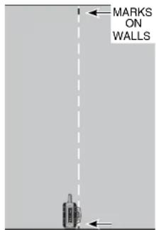
PLUMB ERROR CHECK (FIG. 19)
- Using a standard plumb bob as a reference, mark the top and bottom of a wall. (Be sure to mark the wall and not the floor and ceiling.)
- Position the rotary laser securely on the floor approximately 3' (1 m) from the wall.
- Turn the laser on, and point the dot at the mark on the bottom of the wall. Then, using the up/down arrows on the remote control, rotate the dot upwards. If the center of the dot scans over the mark on the top of the wall, the laser is properly calibrated.
NOTE: This check should be done with a wall no shorter than the tallest wall for which this laser will be used.
FIG. 19
Repairs
The charger is not serviceable. There are no serviceable parts inside the charger.
To assure product SAFETY and RELIABILITY, repairs, maintenance and adjustments should be performed by a DEWALT factory service center, a DEWALT authorized service center or other qualified service personnel. Always use identical replacement parts.
Three Year Limited Warranty
DEWALT will repair, without charge, any defects due to faulty materials or workmanship for three years from the date of purchase. This warranty does not cover part failure due to normal wear or tool abuse. For further detail of warranty coverage and warranty repair information, visit www.dewalt.com or call 1-800-4-DEWALT (1-800-433-9258). This warranty does not apply to accessories or damage caused where repairs have been made or attempted by others. This warranty gives you specific legal rights and you may have other rights which vary in certain states or provinces.
In addition to the warranty, DEWALT tools are covered by our:
1 YEAR FREE SERVICE
DEWALT will maintain the tool and replace worn parts caused by normal use, for free, any time during the first year after purchase.
2 YEARS FREE SERVICE ON DEWALT BATTERY PACKS
DC9096, DC9091, DC9071, DC9360 and DC9280
90 DAY MONEY BACK GUARANTEE
If you are not completely satisfied with the performance of your DEWALT Power Tool, Laser, or Nailer for any reason, you can return it within 90 days from the date of purchase with a receipt for a full refund – no questions asked.
LATIN AMERICA: This warranty does not apply to products sold in Latin America. For products sold in Latin America, see country specific warranty information contained either in the packaging, call the local company or see website for warranty information.
FREE WARNING LABEL REPLACEMENT: If your warning labels (Fig. 1) become illegible or are missing, call 1-800-4-DEWALT for a free replacement.
POUR TOUTE QUESTION OU COMMENTAIRE RELATIF A CET OUTIL OU TOUT AUTRE OUTIL DEWALT, COMPOSEZ GRATUITEMENT LE : 1-800-4-DEWALT (1-800-433-9258).
ARRÊT DU LASER
natural_image
Exterior view of a DeWalt industrial machine (no signage or text beyond branding)INSTALLATION SUR UNE TIGE GRADUÉE (FIG. 12)
ENCENDIDO DEL LÁSER (FIG. 3)
natural_image
Exterior view of a DeWalt industrial device (no signage or text beyond branding)MODALIDAD DE NIVEL
natural_image
Close-up of a hand holding a small electronic device with a dial and screen (no visible text or symbols)Local D, Col. Obrera (55) 5588 9377
MERIDA, YUC
Calle 63 #459-A - Col. Centro (999) 928 5038
MONTERREY, N.L.
Av. Francisco I. Madero 831 Poniente - Col. Centro (818) 375 23 13
PUEBLA, PUE
17 Norte #205 - Col. Centro (222) 246 3714
QUERETARO, QRO
Av. San Roque 274 - Col. San Gregorio (442) 2 17 63 14
SAN LUIS POTOSI, SLP
DW079 9,6 -18,0 V DC
= 0 - 600 rpm
SOLAMENTE PARA PROPÓSITO DE MÉXICO:
IMPORTADO POR: DEWALT S.A. DE C.V.
BOSQUES DE CIDROS, ACCESO RADIATAS NO.42
DEWALT Battery and Charger Systems
| Battery Output | Charges/Charge Time - Chargeurs/Durio de charge (Minutes) - Cargadores de batteries/Temps de cargo (Minutes) | ||||||||||||||||
| 120 Volts | 12 Volts | ||||||||||||||||
| Cat Number | Voltage | DW9106 | DW9118 | DW9107 | DW9108 | DW9116 | DW9216 | DW9117 | DW911 | DC011 | DC9000 | DC9310 | DC9320 | DW0246 | DW0249 | DW9109 | DC9319 |
| DC9380 | 36 | X | X | X | X | X | X | X | X | X | 60 | X | X | X | X | X | X |
| DC9280 | 28 | X | X | X | X | X | X | X | X | X | 60 | X | X | X | X | X | X |
| DW0242 | 24 | X | X | X | X | X | X | X | X | X | X | X | X | 60 | 60 | X | X |
| DC9296 | 18 | X | X | X | 60 | 60 | 60 | 20 | 60 | 60 | X | 60 | 60 | X | X | 60 | 60 |
| DC9099 | 18 | X | X | X | 45 | 45 | 45 | 15 | 45 | 45 | X | 45 | 45 | X | X | 45 | 45 |
| DC9180 | 18 | X | X | X | X | X | X | X | X | X | X | 60 | 60 | X | X | X | 60 |
| DW9296 | 18 | X | X | X | 60 | 60 | 60 | 20 | 60 | 60 | X | 60 | 60 | X | X | 60 | 60 |
| DW9288 | 18 | X | X | X | 30 | 30 | 30 | 12 | 30 | 30 | X | 30 | 30 | X | X | 30 | 30 |
| DW9099 | 18 | X | X | X | 45 | 45 | 45 | 15 | 45 | 45 | X | 45 | 45 | X | X | 45 | 45 |
| DC9301 | 14.4 | 90 | 115 | 60 | 60 | 60 | 60 | 20 | 60 | 60 | X | 60 | 60 | X | X | 60 | 60 |
| DC9394 | 14.4 | 60 | 90 | 45 | 45 | 45 | 45 | 15 | 45 | 45 | X | 45 | 45 | X | X | 45 | 45 |
| DW9391 | 14.4 | 60 | 90 | 45 | 45 | 45 | 45 | 15 | 45 | 45 | X | 45 | 45 | X | X | 45 | 45 |
| DW9394 | 14.4 | 45 | 80 | 30 | 30 | 30 | 30 | 12 | 30 | 30 | X | 30 | 30 | X | X | 30 | 30 |
| DC9071 | 12 | 90 | 115 | 60 | 60 | 60 | 60 | 20 | 60 | 60 | X | 60 | 60 | X | X | 60 | 60 |
| DW9350 | 12 | 40 | X | X | X | X | X | X | X | X | X | X | X | X | X | X | X |
| DW9071 | 12 | 60 | 90 | 45 | 45 | 45 | 45 | 15 | 45 | 45 | X | 45 | 45 | X | X | 45 | 45 |
| DW9072 | 12 | 45 | 60 | 30 | 30 | 30 | 30 | 12 | 30 | 30 | X | 30 | 30 | X | X | 30 | 30 |
| DW9048 | 9.6 | 40 | X | X | X | X | X | X | X | X | X | X | X | X | X | X | X |
| DW9061 | 9.6 | 60 | 90 | 45 | 45 | 45 | 45 | 15 | 45 | 45 | X | 45 | 45 | X | X | 45 | 45 |
| DW9062 | 9.6 | 45 | 60 | 30 | 30 | 30 | 30 | 12 | 30 | 30 | X | 30 | 30 | X | X | 30 | 30 |
| DW9057 | 7.2 | 45 | 80 | 30 | 30 | 30 | 30 | 12 | 30 | 30 | X | 30 | 30 | X | X | 30 | 30 |
X Indicates that the battery pack is not compatible with that specific charger.
All charge times are approximate. Actual charge time may vary.
Read the instruction manual for more specific information.
DEWALT Industrial Tool Co., 701 East Joppa Road, Baltimore, MD 21286 (FEB08) Part No. 648492-00 DW079 Copyright © 2008 DeWALT The following are trademarks for one or more DEWALT power tools: the yellow and black color scheme; the "D" shaped air intake grill; the array of pyramids on the handgrip; the kit box configuration; and the array of lozenge-shaped humps on the surface of the tool.