
DW876 - Saw DEWALT - Free user manual and instructions
Find the device manual for free DW876 DEWALT in PDF.


User questions about DW876 DEWALT
0 question about this device. Answer the ones you know or ask your own.
Ask a new question about this device
Download the instructions for your Saw in PDF format for free! Find your manual DW876 - DEWALT and take your electronic device back in hand. On this page are published all the documents necessary for the use of your device. DW876 by DEWALT.
USER MANUAL DW876 DEWALT
text_image
Technical diagram of a mechanical testing machine with numbered components for identification.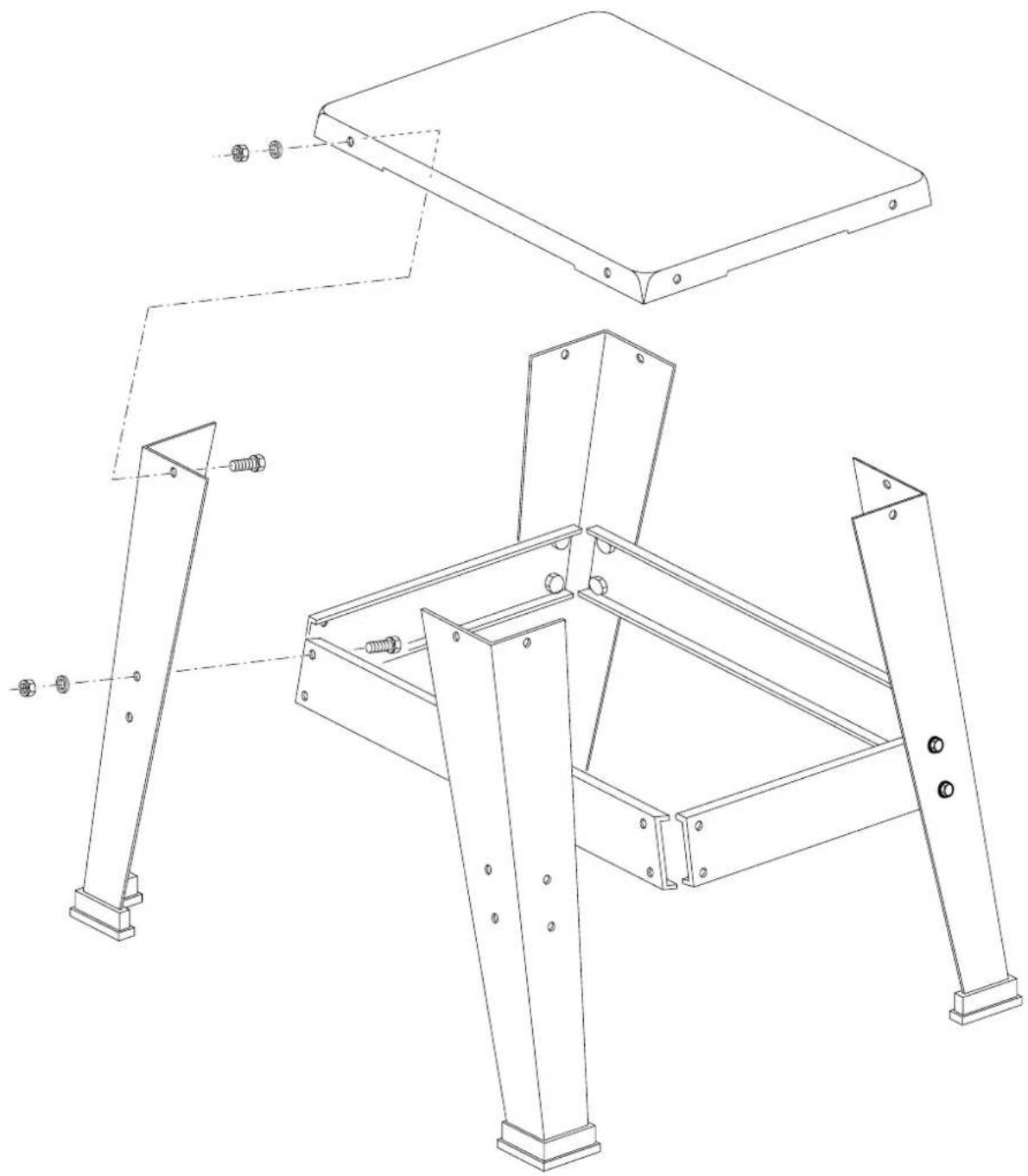
natural_image
Technical line drawing of a mechanical frame assembly with mounting brackets and bolts (no text or symbols)B

text_image
Technical diagram of a mechanical device with numbered components labeled 11, 12, and 17
text_image
11096C
DeWALT®
DW876 - TYPE 2
text_image
15 40 41 7 39 42A
natural_image
Technical line drawing of a mechanical assembly with pulleys and wheels (no text or symbols)X
natural_image
Technical line drawing of a mechanical assembly with components like a fan, motor, and mounting bracket (no text or symbols)Y
1
natural_image
Pure mechanical diagram showing a lever mechanism with no text or symbols2
natural_image
Technical line drawing of a mechanical device with fan-like components and an inset showing a circular detail (no text or symbols)3
natural_image
Mechanical diagram showing a rotating platform with a rotating shaft and rotational arrow (no text or symbols)Z
Dansk
DW876-TYPE 2 - SUPPLERENDE OPLYSNINGER
| Tekniske data | |
| DW876-TYPE 2 | |
| Motorefeld W 750 | |
| Belastning motorhasighted min | 2.900 |
| Kinge | |
| Lengde mm 2.215 | |
| Bredde mm 3 - 16 | |
| Totted mm 0.6 | |
EC-Declaration of conformity

DW876-TYPE 2
DLWALT declares that these power tools have been designed in compliance with 98/3//EEC, 89/336/EEC, 73/23/EEC. EN 61029-1:2003, EN 61029-2-5:2002, EN 294:1987.
For more information, please contact DeWALT at the address below or refer to the back of the manual.
| DW876-TYPE 2 | |
| L_max (sound pressure) | dB(A)* 52 |
| L_max (accurate power) | dB(A) 89 |
| * at the operator's ear | |
| R_max (sound pressure uncertainty) | dB(A) 3 |
| K_max (accurate power uncertainty) | dB(A) 3 |
Director Engineering and Product Development
Horst Großmann
D-65510, Istein, Germany
Safety Instructions
- Keep other persons away from the work area. Do not allow children, visitors
of animals to come near the work area or to touch the tool or the mains cabr - Do not force the tool. The tool will do the job better and safer at the rate for which it was intended.
- Use the appropriate tool. The intended use is described in this instruction manual. Do not force small tools or attachments to do the job of a heavy-duty tool. Do not use tools for purposes not intended; for example: do not use cardsaws to cut trees or logs.
• This machine is not intended for serial or conveyor belt production. - Do not overreach. Keep proper footing and balance at all times
- Wear ear protection at all times.
- Use a holder or wear gloves when handling a saw blade.
- Select the correct blade for the different type of speed settings and the
material to be cut. - Observe the maximum speed marked on the saw blade.
- Do not use saw blades that do not conform to the dimensions stated in the technical data.
- Do not use deformed or damaged saw blades.
- Connect the machine to a dust collection device when sawing wood.
- When performing bevel cuts, ensure that the fence is fixed on the lower side
of the table. - Keep the push stick in its place when not in use.
- Always support long pieces.
- Never perform any cleaning or maintenance work when the machine is still running.
The following factors are of influence to noise production:
- the material to be cut
- the support of the material
- the saw blade tension
- the type of saw blade
- the feed force
- correct adjustment and regular maintenance of the saw blade
- regular maintenance of the blade wheel and blade guard
- regular maintenance of the lubrication system
Labels on tool
The following pictograms are shown on the tool:

Unplug the tool when not in use, before changing any parts of the tools, accessories or attachments and before servicing.

Check the direction of rotation of the blade.

Do not place your hands within this area

Carrying point.
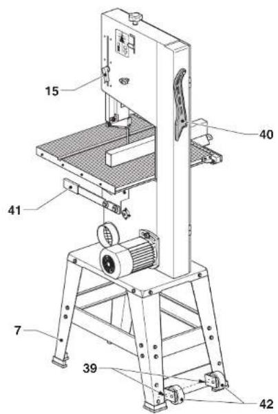
Description (fig. A)
7 Loceland
15 Blade guard height adjuster
39 Floor anchor hole
40 Push stock location
41 Carrying handle
42 Wheel
Electrical safety
This machine is of class I construction; therefore earthed (grounded) connection is required.
Assembly and adjustment
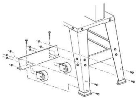
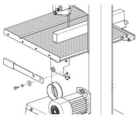
Mounting the wheels (Fig. X)
- Fit the plate to the legstand using the fasteners.
- Hold the first wheel bracket in front of the plate, aligning the mounting holes.
- Fit the bracket to the plate using the fasteners.
- Repeat as for the other wheel bracket
- Adjust the clearance of the wheels to the ground to 0 - 0.5 mm,
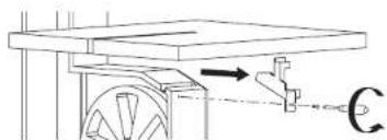
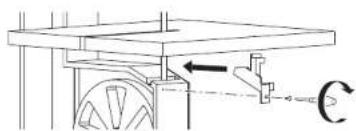
Fitting the carrying handle (fig. Y)
- Hold the handle in front of the mounting location to the right of machine.
• Fit the handle using the screw.
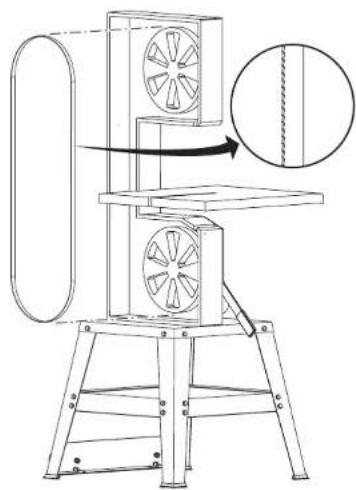
Mounting the saw blade
Refer to fig. Z.
Installing the machine
• Always bolt the machine to the floor using the floor anchor holes provided
Instructions for use
- Turn the knob (15) in order to properly adjust the height of the guard
- The red power on indicator is on when the machine is running.
Transporting
The castor wheels provide an easier transport of the machine.
- Transport the machine using the carrying handle (41).

Always transport the machine with the guard fully down and close to the table. Never carry the machine by the guard.
Maintenance

Prior to maintenance always unplug the too.
- Regularly clean the blade wheel.
- Regularly clean the blade guard.
- Regularly check that the blade guidance system functions property.
Español
Director Engineering and Product Development
Horsl Großmann
DW876-TYPE 2 - INFORMATIONS ADDITIONNELLES
Director Engineering and Product Development
Horsl Großmann
Director Engineering and Product Development
Horst Großmann
15 Hoydejustering for bladvernet
39 Forankingshul i guly
Director Engineering and Product Development
Horst Großmann
Director Engineering and Product Development
Horst Großmann
Director Engineering and Product Development Horst Großmann
natural_image
Illustration of a hand operating a film reel with a numbered label (22), no text or symbols present.
Dansk 1
Deutsch 6
English 11
Español 16
Français 21
Italiano 26
Nederlands 30
Norsk 36
Português41
Suomi 46
Svenska 51
Ελληνικα 56
| Belgique et Luxembourg DeWALT Tel: 02 | 719 07 12 | ||
| België en Luxemburg Weihoek 1, Nossegem Fax: 02 | 721 40 45 | ||
| 1930 Zaventem-Zuid Service fax: 02 | 719 08 10 | ||
| Danmark D | EWALT Tlf: 70Hejrevang 26 B Fax: 483450 Allerød | 20 15 1014 13 99 | |
| Deutschland D | EWALT Tel: 06Richard-Klinger-Straße, Postfach 1202 Fax: 06165510 Idstein | 12 62 1626 21 24 40 | |
| Ελλάς D | EWALT Tηλ: 019Λεωφ Συγγρού 154 Fax: 019176 71 ΚαλλιθέαAθήνα | Service: 019 | 24 28 7024 28 6924 28 76-7 |
| España | DEWALT Tel: 977Ctra de Accesoa Roda de Barà, km 0,743883 Roda de Barà, Tarragona | Fax: 977Fax: 977 | 29 71 0029 71 3829 71 19 |
| France | DEWALT Tel: 72Le PaisyBP 2169571 Dardilly Cedex | Tlx: 30Fax: 72 | 20 39 2062 24F20 39 00 |
| HelvetiaSchweiz | DEWALT/Rofo AGWarpel3186 Düdingen | Tel: 037Fax: 037 | 43 40 6043 40 61 |
| Ireland | DEWALT Tel: 012Calpe House Rock HillBlack RockCo. Dublin | Fax: 012 | 78 18 0078 18 11 |
| Italia | DEWALT Tel: 03Viale Elvezia 220052 Monza (Mi) | Fax: 03 | 92 38 72 0492 38 75 93 |
| Nederland | DEWALT Tel: 07Florijnstraat 104879 AH Etten-Leur | Fax: 07 | 65 08 22 0165 03 81 84 |
| Norge | DEWALT Tel: 22Strømsveien 3441081 Oslo | Fax: 22 | 90 99 0090 99 01 |
| Österreich | DEWALT Tel: 022Werkzeugevertriebs GmbHErlaaerstraße 165Postfach 320,1231 Wien | Tlx: 13228 Fax: 022 | 26 61 16Black A26 61 16 14 |
| Portugal | DEWALT Tel: 468 7513/7613Rua Egas Moniz 173Apartado 19, S. João do Estoril2768 Estoril, Codex | Tlx: 16607 Fax: 466 | Bladec P38 41 |
| Suomi | DEWALTRälssitie 7 C01510 Vantaa | Puh: +35 89Fax: +35 89 | 825 45 40825 45 444 |
| Frälsevägen 7 C01510 Vanda | Tel: +35 89Fax: +35 89 | 825 45 40825 45 444 | |
| Sverige | DEWALT Tel: 031Box 603421 26 Västra FrölundaBesöksadr. Ekonomivägen 11 | Fax: 031 | 68 61 0068 60 08 |
| United Kingdom | DEWALT Tel: 017210 Bath RoadSloughBerks SL1 3YD | Fax: 017 | 53 57 42 7753 52 13 12 |
TO HASTIGHEDERS BÅNDSAV DW876
Tillykke!
1 Schlüssel 10/13 mm
TWO SPEED BANDSAW DW876
Congratulations!
You have chosen a DeWALT product. Years of experience, thorough product development and innovation make DeWALT one of the most reliable partners for professional users.
Table of contents
| Technical data en - 1 |
| Declaration of conformity en - 1 |
| Safety instructions en - 2 |
| Package contents en - 3 |
| Description en - 3 |
| Assembly and adjustment en - 3 |
| Instructions for use en - 4 |
| Maintenance en - 5 |
| Guarantee en - 5 |
Technical data
| DW876 | |
| Motor power (input) W 1000 | |
| Motor power (output) W 750 | |
| Voltage V 230 | |
| No load speed | |
| 1st gear m/min 380 | |
| 2nd gear m/min 880 | |
| Max. cutting height | mm 200 |
| Max. cutting width | mm 315 |
| Table size | mm 500 x 500 |
| Table inclination | right 0 - 45° |
| Overall dimensions (without legstand) | mm 1050 x 700 x 500 |
| (with legstand) | mm 1600 x 700 x 500 |
| Dust extraction adaptor, ø | mm 100 |
| Blade width | mm 4 - 20 |
| Weight | kg 44.5 |
Standard equipment:
Legstand, general purpose blade, rip fence, mitre fence.
| Fuses: | |
| Europe | 230 V tools 10 Amperes, mains |
| UK & Ireland | 13 Amperes, in plug |
The following symbols are used throughout this manual:

Denotes risk of personal injury, loss of life or damage to the tool in case of non-observance of the instructions in this manual.

Denotes risk of electric shock.

Sharp edges.
Declaration of conformity

DW876
D≡WALT declares that these Power Tools have been designed in compliance with: 89/392/EEC, 89/336/EEC, 73/23/EEC, EN 61029, EN 55104, EN 55014, EN 61000-3-2 & EN 61000-3-3.
Level of sound pressure according to 86/188/EEC & 89/392/EEC, measured according to DIN 45635:
| DW876 | |||
| L_pA | (sound pressure) | dB(A)^a | 84.0 |
| L_wa | (acoustic power) | dB(A) | 92.0 |
* at the operator's ear

Take appropriate measures for the protection of hearing if the sound pressure of 85 dB(A) is exceeded.
Weighted root mean square acceleration value according to DIN 45675:
| DW876 | |
| < 2.5 m/s ^2 |
TÜV Rheinland
Director Engineering & Product Development Horst Großmann
text_image
H. JopmanDeWALT, Idstein, Germany
Safety instructions
When using Power Tools, always observe the safety regulations applicable in your country to reduce the risk of fire, electric shock and personal injury. Read the following safety instructions before attempting to operate this product. Keep these instructions in a safe place!
General
1 Keep work area clean
Cluttered areas and benches can cause accidents.
2 Consider work area environment
Do not expose Power Tools to humidity. Keep work area well lit. Do not use Power Tools in the presence of inflammable liquids or gases.
3 Guard against electric shock
Prevent body contact with earthed surfaces (e.g. pipes, radiators, cookers and refrigerators). For use under extreme conditions (e.g. high humidity, when metal swarf is being produced, etc.) electric safety can be improved by inserting an isolating transformer or a (FI) earth-leakage circuit-breaker.
4 Keep children away
Do not let children come into contact with the tool or extension cord. Keep all people away from the work area.
5 Extension cords for outdoor use
When the tool is used outdoors, always use extension cords intended for outdoor use and marked accordingly.
6 Store idle tools
When not in use, Power Tools must be stored in a dry place and locked up securely, out of reach of children.
7 Dress properly
Do not wear loose clothing or jewellery. They can be caught in moving parts. Preferably wear rubber gloves and non-slip footwear when working outdoors. Wear protective hair covering to keep long hair out of the way.
8 Wear safety goggles
Also use a face or dust mask in case the operations produce dust or flying particles.
9 Beware of maximum sound pressure
Take appropriate measures for the protection of hearing if the sound pressure of 85 dB(A) is exceeded.
10 Secure workpiece
Use clamps or a vice to hold the workpiece. It is safer and it frees both hands to operate the tool.
11 Do not overreach
Keep proper footing and balance at all times.
12 Avoid unintentional starting
Do not carry the plugged-in tool with a finger on the switch. Be sure that the switch is released when plugging in.
13 Stay alert
Watch what you are doing. Use common sense. Do not operate the tool when you are tired.
14 Disconnect tool
Shut off power and wait for the tool to come to a complete standstill before leaving it unattended. Unplug the tool when not in use, before servicing or changing accessories.
15 Remove adjusting keys and wrenches
Always check that adjusting keys and wrenches are removed from the tool before operating the tool.
16 Use appropriate tool
The intended use is laid down in this instruction manual. Do not force small tools or attachments to do the job of a heavy-duty tool. The tool will do the job better and safer at the rate for which it was intended.
Warning! The use of any accessory or attachment or performance of any operation with this tool, other than those recommended in this instruction manual may present a risk of personal injury.
17 Do not abuse cord
Never carry the tool by its cord or pull it to disconnect from the socket. Keep the cord away from heat, oil and sharp edges.
18 Maintain tools with care
Keep the tools in good condition and clean for better and safer performance. Follow the instructions for maintenance and changing accessories. Inspect the tool cords at regular intervals and, if damaged, have them repaired by an authorized DeWALT repair agent. Inspect the extension cords periodically and replace them if damaged. Keep all controls dry, clean and free from oil and grease.
19 Check for damaged parts
Before using the tool, carefully check it for damage to ensure that it will operate properly and perform its intended function. Check for misalignment and seizure of moving parts, breakage of parts and any other conditions that may affect its operation. Have damaged guards or other defective parts repaired or replaced as instructed. Do not use the tool if the switch is defective. Have the switch replaced by an authorized DeWALT repair agent.
20 Have your tool repaired by an authorized DEWALT repair agent
This Power Tool is in accordance with the relevant safety regulations. To avoid danger, electric appliances must only be repaired by qualified technicians.
Additional Safety Rules for Bandsaws
- It is advisable to wear safety goggles when operating.
- Keep the upper blade guard as close to the workpiece as possible.
- When not in use, protect the saw blade completely using the blade guard.
- When not in use, when changing blades or carrying out maintenance, disconnect the machine from the power supply.
- Before switching ON, make sure that the worktable is secured at the required angle.
• Always use sharp blades of the correct type designed for the workpiece.
- Keep your hands well clear off the blade. Use a push stick for narrow workpieces.
- Always make sure that the table insert is properly located. Replace the insert immediately when worn.
- Never run the machine without all guards in place and the door locked.
- When working under abnormal conditions (exceptionally low temperatures, lower mains supply voltage than normal or following a long period of inactivity) the machine may have a tendency to stick. In such a case, slacken the blade tension to approx. 100 N, switch the motor ON and (while the motor is running) gradually increase the tension to (50 x b) N, where b is the width of the saw blade in mm.
- When the machine is not going to be used for a prolonged period of time, slacken the tensioner completely to eliminate the risk of blade wheel distortion and resulting imbalance.
• Always secure round workpieces.
- Make sure that the blade rotates in the correct direction and that the teeth are pointing downwards.
Residual risks
The following risks are inherent to the use of bandsaws:
- injuries caused by touching the rotating parts
- injuries caused by disruption of the saw blade
These risks are most evident:
- within the range of operation
- within the range of the rotating machine parts
In spite of the application of the relevant safety regulations and the implementation of safety devices, certain residual risks cannot be avoided.
These are:
- Impairment of hearing.
- Risk of accidents caused by the uncovered parts of the rotating saw blade.
- Risk of injury when changing the blade.
- Risk of squeezing fingers when opening the guards.
- Health hazards caused by breathing dust developed when sawing wood, especially oak and beech.
Package contents
The package contains:
1 Partly assembled machine
1 Table
1 Rip fence
1 Mitre fence
1 Box containing:
1 legstand (4 legs 530 mm, 2 traverse rails 480 mm, 2 traverse rails 360 mm, M5 x 16 bolts, M5 nuts and M5 washers for assembling the legstand, M8 x 20 bolts and washers for mounting the machine onto the legstand)
1 spanner 10/13 mm
1 Allen key 2.5 mm
1 Instruction manual
1 Exploded drawing
- Check for damage to the tool, parts or accessories which may have occurred during transport.
- Take the time to thoroughly read and understand this manual prior to operation.
- Remove the saw from the packaging material carefully.
- Study figure A to become familiar with the terminology used to describe the various parts of the saw.
Description (fig. A)
Your DW876 bandsaw has been designed for professional workshop applications: it performs straight, circular, mitre and bevel cuts. It can cut a wide range of materials such as wood, plastics, non-ferrous metals and leather.
1 ON/OFF-switch
2 Blade
3 Blade guard
4 Table
5 Rip fence
6 Mitre fence
7 Legstand
8 Blade tensioner
9 Door lock
10 Blade tension scale
11 Bevelling table support
12 Locking lever
13 Motor positioning bolt
14 Blade centring adjuster
15 Blade guard height adjuster
16 Dust extraction adapter
Electrical safety
The electric motor has been designed for one voltage only. Always check that the power supply corresponds to the voltage on the rating plate.
Mains plug replacement (U.K. & Ireland only)
- Should your mains plug need replacing and you are competent to do this, proceed as instructed below. If you are in doubt, contact an authorized DtWALT repair agent or a qualified electrician.
- Disconnect the plug from the supply.
- Cut off the plug and dispose of it safely; a plug with bared copper conductors is dangerous if engaged in a live socket outlet.
- Only fit 13 Amperes BS1363A approved plugs fitted with the correctly rated fuse (1).
- The cable wire colours, or a letter, will be marked at the connection points of most good quality plugs. Attach the wires to their respective points in the plug (see below). Brown is for Live (L) (2) and Blue is for Neutral (N) (4).
- Before replacing the top cover of the mains plug ensure that the cable restraint (3) is holding the outer sheath of the cable firmly and that the two leads are correctly fixed at the terminal screws.
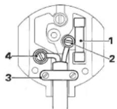
text_image
Technical diagram of an electrical socket with numbered components for identification
Never use a light socket.
Never connect the live (L) or neutral (N) wires to the earth pin marked E or 12
Using an extension cable
If an extension cable is required, use an approved extension cable suitable for the power input of this tool (see technical data). The minimum conductor size is 1.5 mm ^2 .
When using a cable reel, always unwind the cable completely.
Also refer to the table below.
Conductor size (mm²) Cable rating (Amperes)
| 0.75 6 |
| 1.00 10 |
| 1.50 15 |
| 2.50 20 |
| 4.00 25 |
Cable length (m)
7.5 15 25 30 45 60
Voltage Amperes Cable rating (Amperes)
| 220/240 | 0 - 2.0 | 6 | 6 | 6 | |
| 2.1 - 3.4 | 6 | 6 | 6 | ||
| 3.5 - 5.0 | 6 | 6 | 10 | 15 | |
| 5.1 - 7.0 | 10 | 10 | 10 15 15 | ||
| 7.1 - 12.0 | 15 | 15 | 15 15 20 20 | ||
| 12.1 - 20.0 | 20 | 20 | 20 20 25 |
Assembly and adjustment

Prior to assembly and adjustment always unplug the tool.
- The machine is fully assembled except for the legstand and table top.
Assembling the legstand (fig. B)
The legstand components and fasteners are packed separately.
- Assemble the legs and traverse rails using the nuts, bolts and washers as shown. Do not yet tighten all the way.
- Ensure that the plastic feet are all facing downwards. The assembled frame is shown in figure A.
- Place the machine on the legstand, making sure that the machine base fits over the legstand on all four sides.
- Secure the machine to the legstand using the nuts, bolts and washers supplied with the tool.
- Firmly tighten all the bolts.

The machine must be level and stable at all times.
Mounting the table top (fig. C)
- Make sure that the bevelling table support (11) is in horizontal position and that the lever (12) is locked.
-
With the scale (17) to the front, install the table top on the bevelling table support (11) using the four bolts.
-
Refer to the inset in figure C for correct positioning of the bolts. Correct positioning of the table top ensures optimal performance of the blade and prevents damaging the table insert.
- Loosen the lever (12) to tilt the table, lock it again and secure all four bolts temporarily.
- Bring the table back to horizontal position.
Mounting a blade (fig. D1 - D3)

The teeth of a new blade are very sharp and can be dangerous.
- Rotate the door locks (9) half a turn to open the door (fig. D1).
- Loosen the knob (18) to swing away the scale (17).
- Select and unpack an appropriate blade.
- Slacken the blade tensioner (8).
- Open the blade guard (3) (fig. D2).
- Retract the guide assembly (fig. D1).
• Pass the blade through the table slot (19). - Position the blade between the upper and lower guide blocks (20) & (21) (fig. D3).
- Guide the blade over the upper and lower band wheels (22) & (23).
- Make sure the teeth of the blade point down and to the front as shown.
- Swing the scale (17) back to its original position and lock the knob (18).
- Do not yet close the blade guard or the door.
Adjusting the blade tension (fig. E)
The correct tension depends on the width of the blade used. Refer to the scale (24) on the machine.
- Adjust the blade tension using the blade tensioner (8) until the pointer (23) indicates the tension corresponding to the blade width.
Adjusting the blade position (fig. F)
The blade must be centred on the rim of the upper band wheel (22).

Do not touch the blade but rotate the upper band wheel (22) with your finger on one of the spokes.
- While rotating the upper band wheel with one hand, slightly rotate the blade centring adjuster (14, fig. A) with the other.
Adjusting the blade guide blocks and rear support bearings (fig. G)
During the sawing operation, the blade is exposed to frontal and lateral forces. The rear support bearings (25) are positioned 0.5 mm behind the blade to control the blade front-to-back movement. The 45° and 90° guide blocks are positioned 0.1 mm from the blade to control the lateral blade position.
- Tilt the table to 45^ to access the lower guide assembly.
- Loosen the knob (24) and position the rear support bearing (25) 0.5 mm away from the blade (fig. G).
- Tighten the knob (24).
- Loosen all four Allen screws (26), position the blocks 0.1 mm away from the blade and tighten the Allen screws again.
- If required, loosen the nut (27) to move the entire guide assembly.
- Check that the blade runs in the centre of the table insert.
- Tighten all four bolts which secure the table to the bevelling table support.
- Close the blade guard and the door.
Mounting and adjusting the rip fence (fig. H)
The bandsaw table is provided with a U-shaped slot and a scale for the rip fence.
- Loosen the locking knob (28).
- Slide the assembly onto the front of the table using the U-shaped slot (29) as a guide.
-
Tighten the locking knob (28) and check that the fence is parallel to the blade.
-
If adjustment is required, loosen the Allen screws which are accessible through the holes (29A) in the fence and adjust as required.
- Tighten all screws and check again.
Mounting the mitre fence (fig. J)
The bandsaw table is provided with a groove which accepts the mitre fence.
The mitre fence (6) is equipped with an adjustable stop (30). The mitre fence can be locked at any position from 0 to 60° left and right and is locked with the locking knob (31).
- Simply slide the mitre fence onto the table and lock it at the required angle.
Setting the bevel angle (fig. K)
- Loosen the locking lever (12).
- Tilt the table to the required angle and lock the lever.
- To set the angle to 90^ , place a square against the blade and adjust the stop (32) until it touches the underside of the table.
Adjusting the blade guard (fig. L)
The blade guard (3) must always be positioned approximately 10 mm above the surface of the workpiece.
- Adjust the position of the saw blade guard (3) using the adjuster (15).
Changing speed (fig. M1 - M2)
Your DW876 bandsaw has two speeds. The low speed is obtained with the drive belt (33) on the small drive pulley (34). The high speed is obtained with the drive belt (33) on the large drive pulley (35) (fig. M1). For speed rates, refer to the technical data.
- Slacken the motor positioning bolt (13) and move the motor in the slot (36) to relax the drive belt (fig. M2).
- Ease the drive belt from the wheel pulley (37) and subsequently from the drive pulley (34) or (35).
- Reinstall the drive belt on the wheel pulley (37) and the required drive pulley (34) or (35).
- Reposition the motor in the slot (36) to obtain the correct drive belt tension and secure the motor positioning bolt (13).
Consult your dealer for further information on the appropriate accessories.
Instructions for use

• Always observe the safety instructions and applicable regulations.
- Do not force the cutting action. Allow the motor to reach full speed before cutting.
- Select an appropriate saw blade.
- Never run the machine without the guards in place.
- Do not overtension the blade.
The attention of UK users is drawn to the “woodworking machines regulations 1974” and any subsequent amendments.
Switching ON and OFF (fig. A)
The ON/OFF-switch (1) works only when the door is locked.
- I = ON The tool now works in continuous operation.
- 0 = OFF
Basic Saw Cuts
Always position the blade guard approximately 10 mm above the surface of the workpiece.
Ripping
• Install the rip fence as described above.
- Set the rip fence for the width of cut required by using the scale.
- Slowly feed the workpiece into the blade, keeping it firmly pressed onto the table and against the fence. Allow the teeth to cut and do not force the workpiece through the blade. The blade speed should be kept constant.
- Use a push stick when close to the blade.

Always switch OFF the tool when work is finished and before unplugging.
Mitre cuts (fig. N)
- Set the required angle on the mitre fence (6) and secure with the locking knob (31).
- Use the cut length bar (30) if required. Lock the cut length bar in the required position using the screw (38).
• Proceed as for ripping.
Bevel cuts
- Set the table to the required angle.
• Install the fence to the right of the blade.
• Proceed as for ripping.
Compound mitre
This cut is a combination of a mitre and a bevel cut.
- Set the table to the required angle and proceed as for ripping.
Freehand cuts
Freehand cuts are performed without the help of a fence.
- Do not attempt to cut curves smaller than the blade will allow.
Dust extraction (fig. A)
The machine is provided with a dust extraction connection outlet (16).
- Whenever possible, connect a dust extraction device designed in accordance with the relevant regulations regarding dust emission.
Maintenance
Your D=WALT Power Tool has been designed to operate over a long period of time with a minimum of maintenance. Continuous satisfactory operation depends upon proper tool care and regular cleaning.

Unwanted tools and the environment
Take your tool to an authorized DeWALT repair agent where it will be disposed of in an environmentally safe way.
GUARANTEE
• 30 DAY NO RISK SATISFACTION GUARANTEE •
If you are not completely satisfied with the performance of your DEWALT machine, simply return it within 30 days, complete as purchased, to a participating Dealer, or an authorized DEWALT repair agent, for a full refund or exchange. Proof of purchase must be produced.
• ONE YEAR FREE SERVICE CONTRACT •
If you need maintenance or service for your DEWALT machine, in the 12 months following purchase, it will be undertaken free of charge at an authorized DEWALT repair agent. Proof of purchase must be produced. Includes labour and spare parts for Power Tools. Excludes accessories.
- ONE YEAR WARRANTY •
If your D=WALT product becomes defective due to faulty materials or workmanship within 12 months from the date of purchase, we guarantee to replace all defective parts free of charge or, at our discretion, replace the unit free of charge provided that:
• The product has not been misused.
• Repairs have not been attempted by unauthorized persons.
• Proof of purchase date is produced.
This guarantee is offered as an extra benefit and is additional to consumers statutory rights.
For the location of your nearest authorized DEWALT repair agent, please use the appropriate telephone number on the back of this manual.
SIERRA DE CINTA DE DOS VELOCIDADES DW876
¡Enhorabuena!
Director Engineering & Product Development Horst Großmann
text_image
X. JopmanL'emballage contient:
LINTZAAG MET TWEE SNELHEDEN DW876
Gefeliciteerd!
Director Engineering & Product Development Horst Großmann

text_image
H. Jopman- I = AAN De machine is nu in continu bedrijf.
• 0 = UIT
Basis zaagsneden
BÅNDSAG MED TO HASTIGHETER DW876
Gratulerer!
Director Engineering & Product Development Horst Großmann
text_image
X. JopmanDEWALT, Idstein, Tyskland
Sikkerhetsforskrifter
Director Engineering & Product Development Horst Großmann
text_image
H. Jopman15 Tire as chaves de aperto
Director Engineering & Product Development Horst Großmann
text_image
H. JopmanDirector Engineering & Product Development Horst Großmann
text_image
X. JopmanDEWALT, Idstein, Tyskland