BG-PC 2625 T - Gas hedge trimmer EINHELL - Free user manual and instructions
Find the device manual for free BG-PC 2625 T EINHELL in PDF.

User questions about BG-PC 2625 T EINHELL
0 question about this device. Answer the ones you know or ask your own.
Ask a new question about this device
Download the instructions for your Gas hedge trimmer in PDF format for free! Find your manual BG-PC 2625 T - EINHELL and take your electronic device back in hand. On this page are published all the documents necessary for the use of your device. BG-PC 2625 T by EINHELL.
USER MANUAL BG-PC 2625 T EINHELL
GB Original operating instructions Pole-Mounted Petrol-Powered Pruner
natural_image
Close-up of a hand using a screwdriver to adjust or install a small mechanical device (no visible text or symbols)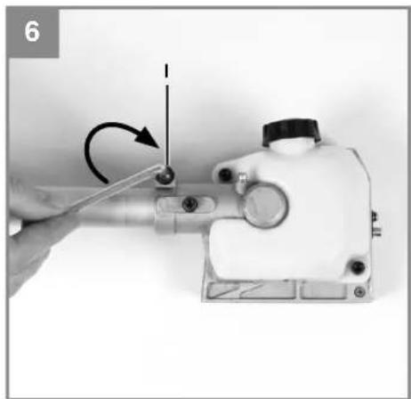
natural_image
Close-up of a hand using a tool to adjust or install a mechanical component, no visible text or symbols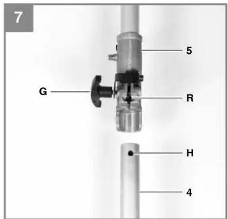
text_image
7 G 5 R H 4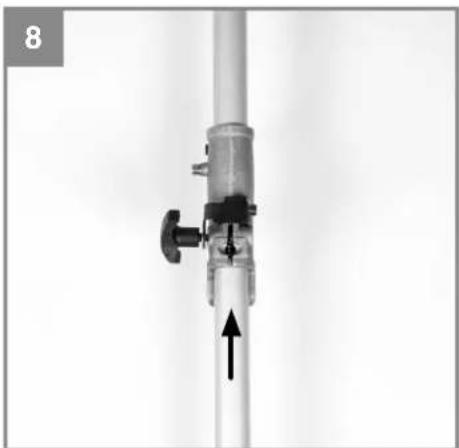
natural_image
Close-up of a vertical cylindrical device with a black arrow pointing upward, no visible text or symbols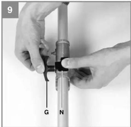
text_image
9 G N
text_image
10 11 N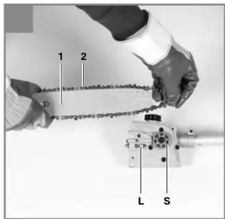
text_image
1 2 L S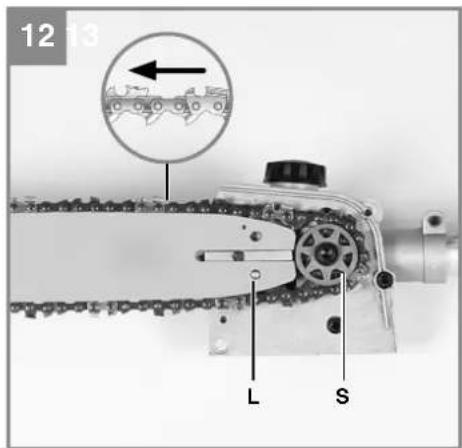
text_image
12 13 L S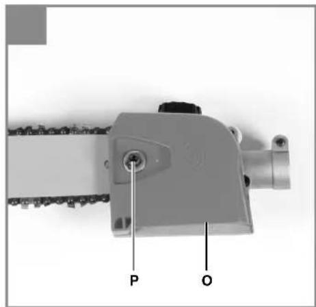
natural_image
Mechanical component with labeled parts P and O, no readable text or symbols beyond labels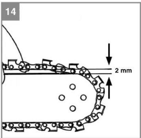
text_image
14 2 mm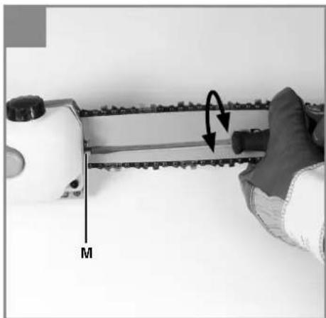
natural_image
Close-up of a hand holding a chain with a measuring tape and a curved arrow indicating rotation (no text or symbols)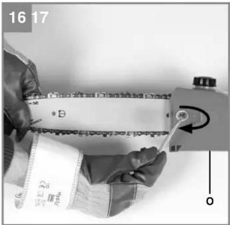
natural_image
Close-up of hands using a tool to measure a mechanical component, no visible text or symbols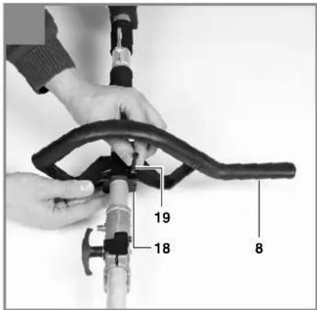
text_image
19 18 8
text_image
18 19 19 20
natural_image
Person holding a metal clamp and cable, no visible text or symbols
natural_image
Person wearing safety harness and gloves, holding a device (no visible text or symbols)
natural_image
Person wearing a seatbelt and holding a key, with an arrow pointing to the buckle (no text or symbols visible)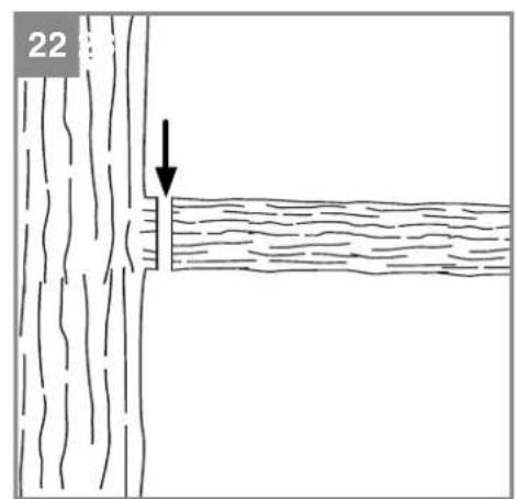
natural_image
Diagram showing a tree trunk with a horizontal line and a downward arrow, labeled '22' in the top-left corner (no text or symbols on the diagram itself)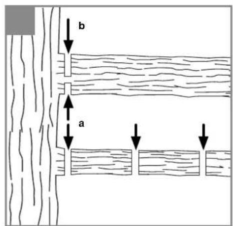
text_image
b a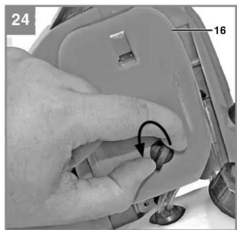
natural_image
Close-up of a hand using a tool to press or adjust a component, with no visible text or symbols.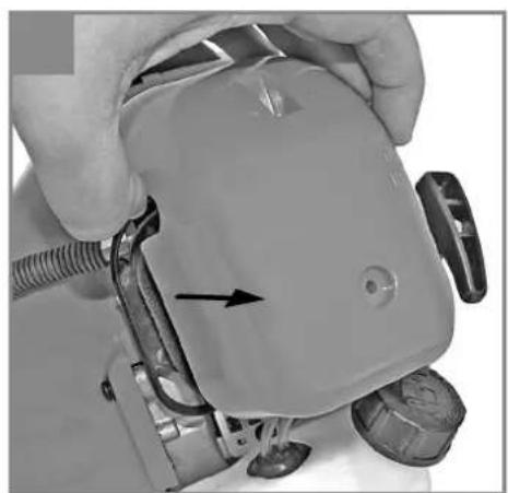
natural_image
Close-up of a hand holding a small electronic device with a black arrow pointing to a component (no visible text or symbols)
natural_image
Close-up of a hand adjusting a mechanical component with a tool, labeled '26 27' and marked with an arrow (no readable text or symbols beyond labels)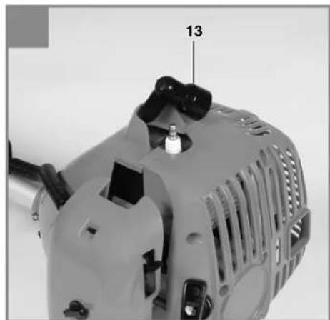
natural_image
Close-up of a gray industrial sewing machine with visible components and mounting bracket (no text or symbols)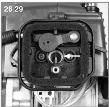
natural_image
Close-up of a mechanical component with internal components and a numbered label (28, 29), no readable text or symbols beyond the number.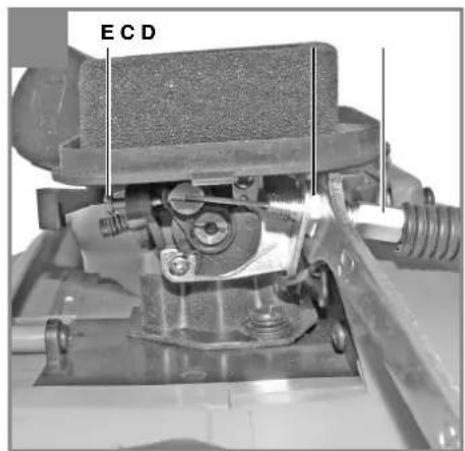
text_image
ECD
text_image
30 1 2 3 4 9 10 10 m 118765-7-
D
Inhaltsverzeichnis
- Safety information
- Layout and items supplied
- Intended use
- Technical data
- Assembly
- Before starting
- Operation
- Working with the chainsaw
- Maintenance
- Disposal and recycling
-
Troubleshooting guide
-
Cleaning, storage, transport and ordering of spare parts
GB
Danger!
When using the equipment, a few safety precautions must be observed to avoid injuries and damage. Please read the complete operating instructions and safety regulations with due care. Keep this manual in a safe place, so that the information is available at all times. If you give the equipment to any other person, hand over these operating instructions and safety regulations as well. We cannot accept any liability for damage or accidents which arise due to a failure to follow these instructions and the safety instructions.
1. Safety information
For the relevant safety information please refer to the booklet included in delivery.
Danger!
Read all the safety information and instructions. Any errors made in following the safety information and the instructions set out below may result in an electric shock, fi re and/or serious injury. Keep all safety information and instructions in a safe place for future use.
Explanation of the symbols on the equipment (Fig. 30):
- Warning!
- Wear protective headgear, goggles and ear muff s.
- Wear safety gloves.
- Watch out for falling and catapulting parts.
- Read the directions for use before operating the equipment.
- Wear sturdy, non-slip footwear.
- Protect the equipment from rain and damp.
- Always switch off the equipment and pull out the spark boot plug before carrying out any maintenance work.
- Electric shock can cause fatal injury. Keep a distance of at least 10 m from power cables.
- Direction of the chain movement and teeth.
- Caution: Hot equipment parts. Keep your distance.
2. Layout and items supplied
2.1 Layout
- Cutter bar
- Saw chain
3a. Oil tank / cap
3b. Gear unit - Drive rod mechanism
- Connecting piece
-
Additional handle
-
Eyelet
-
Handle
-
On/Off switch
-
Throttle lever lock
-
Throttle lock
-
Throttle lever
-
Spark plug boot
-
Starter cable
-
Petrol tank / cap
-
Air filter housing cover
-
Choke lever
-
Clip
-
Screw (4x)
-
Nut (4x)
-
Open-ended wrench size 8/10
-
Allen key size 4mm
-
Allen key size 5mm
-
Cutter guard
-
Carrying strap
-
Oil/petrol mixing bottle
-
Multifunction tool
-
Lubrication nipple
-
Fuel pump „primer“
2.2 Items supplied
Please check that the article is complete as specified in the scope of delivery. If parts are missing, please contact our service center or the sales outlet where you made your purchase at the latest within 5 working days after purchasing the product and upon presentation of a valid bill of purchase. Also, refer to the warranty table in the service information at the end of the operating instructions.
- Open the packaging and take out the equipment with care.
- Remove the packaging material and any packaging and/or transportation braces (if available).
- Check to see if all items are present.
- Inspect the equipment and accessories for transport damage.
- If possible, keep the packaging until the end of the guarantee period.
GB
Danger!
The equipment and packaging material are not toys. Do not let children play with plastic bags, foils or small parts. There is a danger of swallowing or suff ocating!
• Original operating instructions
- Safety information
3. Intended use
The pole-mounted petrol-powered pruner is designed for lopping off tree branches. It is not suitable for extensive sawing work, felling trees or sawing any materials other than wood.
The equipment may be used only for its intended purpose. Any other use is deemed to be a case of misuse.
The user/operator and not the manufacturer will be liable for any damage or injuries of any kind which result from such misuse.
Please note that our equipment has not been designed for use in commercial, trade or industrial applications. Our warranty will be voided if the equipment is used in commercial, trade or industrial businesses or for equivalent purposes.
4. Technical data
Engine type ....2-stroke engine, air-cooled, chrome cylinder
Engine output (max.)....0.8 kW / 1.1 hp
Displacement....25.4cm3
Idle engine speed 3,200 min ^-1
Max. engine speed....9,000 min ^-1
Cutter bar length ....8" (200 mm)
Max. cutting length 180 mm
Chain pitch 9.525 mm (3/8")
Chain thickness 1.27 mm
Chain wheel teeth ....7 teeth / 9.525 mm
Cutting speed at rated rpm 18 m/s
Oil tank capacity 120 ml
Weight without cutter bar and chain ....5.9 kg
Chain....Oregon 91P033X
Cutter bar....Oregon 080SDEA318
Ignition......Electronic
Drive ....Centrifugal clutch
Tank capacity 450 ml
Spark plug ....Champion RCJ6Y
Fuel consumption (specifi c) 582g/kWh
Sound and vibration
L_nA sound pressure level ..... 102 dB(A)
K_pA^pm uncertainty ....3 dB
L_WA sound power level 112 dB(A)
K_WA uncertainty 3 dB
Wear ear-muff s.
The impact of noise can cause damage to hearing.
In operation
Vibration emission value a_n = 14.8m / s^2
K uncertainty = 3 m/s ^4
Reduce noise generation and vibration to a minimum!
- Use only equipment that is in perfect condition.
- Maintain and clean the equipment regularly.
- Adopt your way of working to the equipment.
• Do not overload the equipment.
• Have the equipment checked if necessary. - Switch off the equipment when not in use.
- Wear gloves.
5. Assembly
Danger!
Do not start the chainsaw until it has been fully assembled and the chain tension has been adjusted. Always wear protective gloves when working on the chainsaw to protect yourself against injury.
5.1 Joining the gear unit to the drive rod mechanism (Fig. 4-6)
Tools required: Allen keys size 4mm/5mm (supplied)
Push the gear unit (Item 3b) and the drive rod mechanism (Item 4) into each other. Center both by turning the screw (Item K). Important! Make sure that the screw (Item K) is turned exactly into the guide hole (Item F). Otherwise there is a risk of the upper part of the rod mechanism being damaged. To join the two subassemblies securely together, tighten the screw (Item I). To take apart, proceed in reverse order.
GB
5.2 Joining the drive rod mechanism to the connecting piece (Fig. 7-10)
Open the handle screw (Item G) and push the drive rod mechanism (Item 4) into the connecting piece (Item 5). Make sure that the centering lever (Item R) latches in the guide hole (Item H). Close the guard cap (Item N) and tighten the handle screw. To take apart, undo the handle screw and open the guard cap. Press the centering lever and simultaneously pull the drive rod mechanism out of the connecting piece.
5.3 Fitting the cutter bar and the chain (Fig. 11-16)
Tools required: Allen key size 5mm Remove the chain wheel cover (Fig.13/ Item O) by undoing the fastening screw (Item P). Lay the chain (Item 2) as shown into the groove which runs around the cutter bar (Item 1). Note the alignment of the chain teeth (Fig. 12). Insert the cutter bar as shown in Fig. 12 into the mount at the gear unit. Place the chain round the chain wheel (Item S). Make sure that the teeth of the chain engage securely in the chain wheel. The cutter bar must be hooked into the chain tensioning bolt (Item L). Fit the chain wheel cover. Important! Do not fully tighten the fastening screw until after you have adjusted the chain tension (see section 5.4).
5.4 Tensioning the chain (Fig. 14-16)
Warning! Always pull out the spark boot plug before performing any checks or adjustments. Undo the fastening screw (Item P) of the chain wheel cover by a few turns (Fig. 13). Adjust the chain tension with the chain tensioning screw (Fig. 15/Item M). Turning the screw clockwise increases the chain tension, turning it counterclockwise decreases the chain tension. The chain is correctly tensioned if it can be raised by around 2mm in the middle of the cutter bar (Fig. 14). Tighten the fixing screw of the chain wheel cover (Fig. 16). Important! All the chain links must lie properly in the guide groove of the cutter bar.
Notes on tensioning the chain:
The chain must be properly tensioned to ensure safe operation. When the saw chain can be raised by around 2 mm in the middle of the cutter bar, you know that the chain tension is ideal. During cutting, the temperature of the chain rises and its length changes. It is important therefore to check the chain tension at least every 10 minutes and to adjust it again as required. This applies in particular to new saw chains. When you have fi nished working, slacken the chain again as it will shorten when it cools down. This will help to prevent damage to the chain.
5.5 Fitting the additional handle
Fit the additional handle as shown in Fig. 17-18.
6. Before starting
Each time before use, check the following:
• That there are no leaks in the fuel system.
- That the equipment is in perfect condition and that the safety devices and cutting devices are complete.
• That all screws are securely fastened.
• That all moving parts move smoothly.
6.1 Fuel and oil
Recommended fuels
Use only a mixture of unleaded petrol and special 2-stroke engine oil. Mix the fuel mixture as indicated in the fuel mixing table.
Important: Do not use a fuel mixture which has been stored for longer than 90 days. Important: Never use 2-stroke oil with a recommended mixing ratio of 100:1. The manufacturer's warranty will be voided in case of engine damage due to inadequate lubrication. Important: Only use containers designed and approved for the purpose to transport and store fuel.
Pour the correct quantities of petrol and 2-stroke oil into the mixing bottle (see scale printed on the bottle). Then shake the bottle well.
6.2 Fuel mixing table
Mixing procedure: 40 parts petrol to 1 part oil
| Petrol 2-stroke oil | |
| 1 liter 25 ml | |
| 5 liters 125 ml | |
6.3 Chain lubrication
Important! Never operate the chain if it is not lubricated with saw chain oil. Use of the chainsaw without saw chain oil or if the oil level is below the „min“ mark will damage the chainsaw.
Important! Be aware of the temperature conditions: Different lubricants with completely different viscosities are required at different ambient temperatures. At lower temperatures you will need
GB
low viscosity oils in order to achieve a sufficient lubricating fi Im. However, if the same low viscosity oil is used during the summer it will become even thinner due to the ambient temperatures alone, and as a result the lubricating fi Im could break down, causing the chain to overheat and become damaged. In addition, the chain oil would burn and produce unnecessary pollutants.
Filling the oil tank (Fig. 1):
Place the chainsaw on a fl at surface. Clean the area around the oil tank cap (Fig. 3a) and then clean the oil tank cap. Fill the tank (Item 3a) with saw chain oil. In the process, make sure that no dirt enters the tank, as this could cause the oil nozzle to become blocked. Close the oil tank cap.
7. Operation
Please note that the statutory regulations governing noise abatement may differ from one location to another.
7.1 Starting with a cold engine
Fill the tank with the required amount of oil/petrol mix. See „Fuel and oil“.
- Set the equipment down on a hard, level surface.
- Press the fuel pump (primer) (Fig. 2/Item 29) 10 times.
- Move the On/Off switch (Fig. 2/Item 9) to „I“.
- Secure the throttle lever. To do this, press the throttle lever lock (Fig. 2/Item 11) and then press the throttle lever (Fig. 1/Item 12) and lock the throttle lever by pressing the lock (Fig. 2/Item 10) at the same time.
- Set the choke lever (Fig. 2/Item 17) to „
-
Hold the equipment firmly and pull out the starter cable (Fig. 2/Item 14) until you feel it begin to resist. Then tug sharply on the starter cable 4 times. The equipment should start. Important: Never allow the starter cable to snap back. This may result in damage. Once the engine has started, move the choke lever immediately to "f" and allow the equipment to warm up for approx. 10 seconds. Important: Since the throttle lever is secured, the cutting tool starts to operate when the engine is started. Then release the throttle lever by actuating it once.
-
If the engine does not start up, repeat steps
4-6 above.
Please note: If the engine does not start up even after several attempts, read the section „Engine troubleshooting“.
Please note: Always pull the starter cord out in a straight line. If it is pulled out at an angle, then friction will occur on the eyelet. As a result of this friction, the cable will become frayed and will wear away faster. Always hold the starter handle when the cable retracts.
Never allow the cable to snap back when it has been pulled out.
7.2 Starting with a warm engine
(The equipment has been idle for less than 15-20 min.)
- Set the equipment down on a hard, level surface.
- Switch the On/Of switch to „I“.
- Secure the throttle lever (in the same way as described in „Starting with a cold engine“).
- Hold the equipment firmly and pull out the starter cable until you feel it start to resist. Then tug sharply on the starter cable. The equipment should start after 1-2 tugs. If the equipment does not start after 6 pulls, repeat steps 1 - 7 of the procedure for starting the engine from cold.
7.3 Switching off the engine
Emergency Stop procedure:
If it becomes necessary to stop the equipment immediately, set the On/Off switch to „Stop“ or „0“.
Normal procedure:
Let go of the throttle lever and wait until the engine has changed to idling speed. Then set the On/Off switch to „Stop“ or „0“.
7.4 Fitting the shoulder strap
Important! Always use the shoulder strap when working with the equipment. Switch off the equipment before you take off the shoulder strap (risk of injury).
- Slip the shoulder strap over your shoulder.
- Adjust the length of the shoulder strap so that the strap attachment is at waist level.
7.5 Work practice
Practice all the work steps with the engine switched off before you start to use the equipment.
GB
8. Working with the chainsaw
Preparations
To ensure that you can work safely, check the following points before every use:
Condition of the chainsaw
Before you start your work, inspect the chainsaw for damage to the housing, the chain and the cutter bar. Never use a chainsaw which is obviously damaged.
Oil container
Level of oil in the oil container: Both before and during your work make sure that there is always sufficient oil in the system. To avoid damaging the chainsaw, never run the saw if there is no oil in the system or if the oil drops below the „min“ mark. On average, a single fi lling will last around 10 minutes depending on the number of pauses in cutting and the loads involved.
Chain
Tension of the chain, condition of the cutting elements: The sharper the chain, the easier and more controllable it is to operate the chainsaw. The same also applies to the chain tension. For greater safety you must check the chain tension before your work and at least every 10 minutes during your work. New chains in particular tend to expand more.
Safety clothing
Always wear appropriate tight-fi tting safety clothing such as special trousers which protect against cuts, protective gloves and safety shoes.
Hearing protection and protective goggles
Wear a protective helmet with integral face and hearing protection. This will offer protection against falling branches and recoiling branches.
Safe working
Never stand under the branch you want to saw. Use special caution when working with branches under tension and splintering wood. Possible risk of injury caused by falling branches and catapulting pieces of wood. When the equipment is in operation, keep other persons and animals away from the danger zone. The equipment is not protected from electric shock through contact with high-voltage cables. Keep a minimum distance of 10 m from live cables. Electric shock can cause fatal injury.
When working on slopes always stand to the upper or left or right side of the branch you want to cut. Hold the equipment as close as possible to your body. This will help you to keep your balance.
Cutting techniques
Start with the bottom branches on the tree. This will make it easier for the cut branches to drop. After completing a cut, the weight of the saw will abruptly increase for the operator as the saw is no longer supported by the branch. This can result in you losing control over the saw. Remove the saw from the cut only with the saw chain still running. This will prevent the saw from getting jammed. Never cut with the tip of the saw. Never cut into the bulging branch collar. This will prevent the tree from healing.
Sawing off smaller branches (Fig. 22):
Place the contact surface of the saw onto the branch. This will prevent the saw from making jerky movements when you begin a cut. Exerting slight pressure, guide the saw from the top to the bottom through the branch.
Sawing off large and long branches (Fig. 23): Carry out a relief cut when working on large branches.
Start by sawing through 1/3 of the branch diameter (a) from the top to the bottom with the top side of the cutter bar. Then saw towards the first cut (b) from the top to the bottom with the bottom side of the cutter bar.
Saw off long branches in several steps to keep control over the impact location.
Kick-back
The term „kickback“ describes what happens when the running chainsaw suddenly kicks upward and backward. Usually this is caused by contact between the tip of the cutter bar and the workpiece or by the saw chain becoming trapped. In the event of kickback, large forces occur suddenly and violently. As a result, the chainsaw usually reacts uncontrollably. This can often result in very serious injuries to the worker or persons in the vicinity. The risk of kickback is at its greatest when the saw is positioned for a cut in the region of the tip of the cutter bar, as the leverage effect is greatest there. It is therefore safest to position the saw as flat as possible.
GB
Warning!
- Make sure that the chain tension is always correctly adjusted.
- Only use a chainsaw if it is in perfect working order.
- Only work with a saw chain that has been properly sharpened in accordance with the instructions.
- Never cut with the upper edge or the tip of the cutter bar.
• Always hold the chainsaw firmly with both hands.
Cutting wood which is under tension
Special care is required when cutting wood which is under tension. Cutting wood which is under tension can release the tension, causing the wood to react out of control. In the worst case this can result in severe and even fatal injuries. This type of work must be performed only by specially trained persons.
9. Maintenance
9.1 Replacing the chain and cutter bar
The cutter bar needs to be replaced if
- the guide groove of the cutter bar is worn. Proceed as described in the section „Fitting the cutter bar and the chain“.
9.2 Checking the automatic chain lubrication
You should check the operation of the automatic chain lubrication system on a regular basis in order to guard against overheating and the damage this can cause to the cutter bar and the chain. Point the tip of the cutter bar at a smooth surface (a board or a cut tree face) and allow the chainsaw to run. If you see a growing oil stain on the smooth surface, the automatic chain lubrication system is working properly. If there is no clear oil stain, please refer to the corresponding instructions in the section „Troubleshooting“. If the information contained there still fails to remedy the situation, please contact our service department or another similarly qualified workshop.
Danger!
Do not actually touch the surface with the tip of the cutter bar when performing this test. Keep a safe distance (approx. 20 cm).
9.3 Sharpening the chain
Working eff ectively with the chainsaw is only possible if the chain is in good condition and sharp. This also reduces the risk of kickback.
The chain can be re-sharpened by any dealer. Do not attempt to sharpen the chain yourself unless you have the necessary special tools and experience.
9.4 Maintenance of the air fi iter (Fig. 24-26)
Soiled air fi Iters reduce the engine power by supplying too little air to the carburetor. Regular checks are therefore essential. The air fi liter (T) should be checked after every 25 hours of use and cleaned if necessary. If the air contains a lot of dust, the air fi liter should be checked more frequently.
- Remove the air fi Iter cover (Fig. 24).
- Remove the air fi Iter (Fig. 25/26).
- Clean the air filter by tapping it or blowing it out.
- Assemble in reverse order.
Important: Never clean the air filter with petrol or infl ammable solvents.
9.5 Maintenance of the spark plug (Fig. 27)
Spark plug sparking gap = 0.6mm. Tighten the spark plug with a torque of 12 to 15 Nm. Check the spark plug for dirt and grime after 10 hours of operation and if necessary clean it with a copper wire brush. Thereafter service the spark plug after every 50 hours of operation.
- Pull out the spark boot plug (Fig. 13).
- Remove the spark plug (Fig. 27) with the supplied multifunction tool (27).
- Assemble in reverse order.
9.6 Carburetor settings
Warning! Settings on the carburetor may only be made by authorized customer service personnel. The air filter cover must be removed before carrying out any work on the carburetor, as shown in Fig. 24 and 25.
GB
9.7 Setting the throttle cable
If the maximum speed of the equipment drops over time and you have ruled out all the other possible causes listed in section 12 „Troubleshooting“, it may be necessary to adjust the throttle cable. First of all check whether the carburetor opens fully when the throttle handle is pressed right through. This is the case if the carburetor slide (Fig. 28) is completely opened when the throttle is fully activated. Figure 28 shows the correct setting. If the carburetor slide is not completely open, it must be adjusted. The following steps are required to adjust the throttle cable: Undo the lock nut (Fig. 29/Item C) a few turns. Turn out the adjusting screw (Fig. 29/Item D) until the carburetor slide is completely open when the throttle is fully activated, as shown in Figure 28. Retighten the lock nut.
9.8 Setting the idling speed
Warning! Set the idling speed when the equipment is warm.
If the engine stalls when the throttle is not pressed and you have ruled out all the other possible causes listed in section 12 „Troubleshooting“, the idling speed must be adjusted. To do this, turn the idling speed screw (Fig. 29/Item E) clockwise until the equipment runs smoothly at idling speed. If the idling speed is so fast that the cutting tool turns as well, it has to be reduced by turning the idling speed screw for as long as is required for the cutting tool to stop turning as well.
9.9 Applying grease to the gear unit
After every 20 hours of use add a little gear grease (approx. 10 g.) at the lubrication nipple (Fig. 4/Item 28).
10. Cleaning, storage, transport and ordering of spare parts
10.1 Cleaning
- Regularly clean the tensioning mechanism by blowing it out with compressed air or cleaning it with a brush. Do not use any tools for cleaning.
- Keep the handles free of oil so that you can maintain a firm grip.
- Clean the equipment as required with a damp cloth and, if necessary, mild washing up liquid.
- If you are not going to use the chainsaw for an extended period of time, remove the chain oil from the tank. Briefly immerse the saw chain and the cutter bar into an oil bath and then wrap them in oil paper.
Important!
Always pull out the spark boot plug each time before carrying out any cleaning. Never immerse the equipment in water or other liquids in order to clean it.
Store the chainsaw in a safe and dry place out of the reach of children.
10.2 Storage
Notice! Never put the equipment into storage for longer than 30 days without carrying out the following steps.
Storing the equipment
If you intend to store the equipment for longer than 30 days, the equipment must be prepared accordingly. Otherwise the fuel still remaining in the carburetor will evaporate and leave a rubbery sediment. This can cause problems when starting up the equipment and may require expensive repairs.
- Slowly remove the fuel tank cap to release any pressure that may have formed in the tank. Carefully empty the tank.
- To remove the fuel from the carburetor, start the engine and let it run until the equipment stops.
- Leave the engine to cool (approx. 5 minutes).
- Remove the spark plug (see section 9.5).
- Add one teaspoon of 2-stroke engine oil into the combustion chamber. Slowly pull the starter cord several times to apply a layer of oil to all internal components. Fit the spark plug again.
GB
Note: Store the equipment in a dry place and far away from possible ignition sources such as an oven, a gas-fired hot water boiler, a gas-fired dryer, etc.
Putting the equipment back into operation
- Remove the spark plug (see section 9.5).
- Quickly tug on the starter cord to remove excess oil from the combustion chamber.
- Clean the spark plug and check that the electrode gap is correct, or insert a new spark plug with the correct electrode gap.
- Prepare the equipment for operation.
- Fill the tank with the relevant mixture of fuel and oil. See the section „Fuel and oil“.
10.3 Transport
To transport the machine, empty the petrol tank as described in section 10. Clean coarse dirt off the equipment with a brush or hand brush. Dismantle the drive rod mechanism as described in section 5.2.
10.4 Ordering spare parts
Please provide the following information on all orders for spare parts:
• Model/type of the equipment
• Article number of the equipment
• ID number of the equipment
• Part number of the required spare part For our latest prices and information please go to www.isc-gmbh.info
11. Disposal and recycling
The equipment is supplied in packaging to prevent it from being damaged in transit. The raw materials in this packaging can be reused or recycled. The equipment and its accessories are made of various types of material, such as metal and plastic. Defective components must be disposed of as special waste. Ask your dealer or your local council.
12. Troubleshooting guide
The table below contains a list of fault symptoms and explains what you can do to remedy the problem if your equipment fails to work properly. If the problem still persists after working through the list, please contact your nearest service workshop.
| Fault Possible cause Remedy | ||
| The equipment does not start | - Correct starting procedure not followed- Sooted or damp spark plug- Incorrect carburetor setting | - Follow the instructions for starting- Clean the spark plug or replace it with a new one- Contact an authorized customer service outlet or send the equipment to ISC GmbH |
| The equipment starts but does not develop its full power | - Incorrect choke lever setting- Soiled air fi lter- Incorrect carburetor setting | - Set the choke lever to “- Clean the air fi lter- Contact an authorized customer service outlet or send the equipment to ISC GmbH |
| The engine does not run smoothly | - Incorrect electrode gap on the spark plug- Incorrect carburetor setting | - Clean the spark plug and adjust the electrode gap, or fi t a new spark plug- Contact an authorized customer service outlet or send the equipment to ISC GmbH |
| Engine smokes excessively | - Incorrect fuel mix- Incorrect carburetor setting | - Use the correct fuel mix (see fuel mixing table)- Contact an authorized customer service outlet or send the equipment to ISC GmbH |
| Saw chain is dry - No oil in the tank- Vent in the oil tank cap is blocked- Oil outlet blocked | - Top up with oil- Clean the oil tank cap- Clear the oil outlet | |
| Chain/guide bar is hot | - No oil in the tank- Vent in the oil tank cap is blocked- Oil outlet is blocked- Chain is blunt- Chain is overtensioned | - Top up with oil- Clean the oil tank cap- Clear the oil outlet- Re-sharpen or replace the chain- Check the chain tension |
| Chainsaw judders, vibrates or does not saw properly | - Chain is undertensioned- Chain is blunt- Chain is worn- Saw teeth point in the wrong direction | - Adjust the chain tension- Re-sharpen or replace the chain- Replace the chain- Refit the chain with the teeth facing in the correct direction |
GB
The reprinting or reproduction by any other means, in whole or in part, of documentation and papers accompanying products is permitted only with the express consent of the iSC GmbH.
Subject to technical changes
GB
Service information
We have competent service partners in all countries named on the guarantee certificate whose contact details can also be found on the guarantee certificate. These partners will help you with all service requests such as repairs, spare and wearing part orders or the purchase of consumables.
Please note that the following parts of this product are subject to normal or natural wear and that the following parts are therefore also required for use as consumables.
| Category Example | |
| Wear parts* | Cutter bar, spark plug, air filter, petrol filter |
| Consumables* Saw chain | |
| Missing parts |
* Not necessarily included in the scope of delivery!
In the effect of defects or faults, please register the problem on the internet at www.isc-gmbh.info. Please ensure that you provide a precise description of the problem and answer the following questions in all cases:
• Did the equipment work at all or was it defective from the beginning?
• Did you notice anything (symptom or defect) prior to the failure?
• What malfunction does the equipment have in your opinion (main symptom)?
Describe this malfunction.
GB
Warranty certifi cate
Dear Customer,
All of our products undergo strict quality checks to ensure that they reach you in perfect condition. In the unlikely event that your device develops a fault, please contact our service department at the address shown on this guarantee card. You can also contact us by telephone using the service number shown. Please note the following terms under which guarantee claims can be made:
- These guarantee conditions regulate additional guarantee services. Your statutory guarantee claims are not affected by this guarantee. Our guarantee is free of charge to you.
-
Our guarantee only covers defects suffered by the device which have been verifiably caused by a material or manufacturing fault and is limited to the rectification of such defects or the replacement of the device at our discretion.
Please note that our devices are not designed for use in commercial, trade or professional applications. A guarantee contract will not be created if the device has been used by commercial, trade or industrial business or has been exposed to similar stresses during the guarantee period. -
The following are not covered by our guarantee:
- Damage to the device caused by a failure to follow the assembly instructions or due to incorrect installation, a failure to follow the operating instructions (for example connecting it to an incorrect mains voltage or current type) or a failure to follow the maintenance and safety instructions or by exposing the device to abnormal environmental conditions or by lack of care and maintenance.
- Damage to the device caused by abuse or incorrect use (for example overloading the device or the use or unapproved tools or accessories), ingress of foreign bodies into the device (such as sand, stones or dust, transport damage), the use of force or damage caused by external forces (for example by dropping it). - Damage to the device or parts of the device caused by normal or natural wear or tear or by normal use of the device.
-
The guarantee is valid for a period of 24 months starting from the purchase date of the device. Guarantee claims should be submitted before the end of the guarantee period within two weeks of the defect being noticed. No guarantee claims will be accepted after the end of the guarantee period. The original guarantee period remains applicable to the device even if repairs are carried out or parts are replaced. In such cases, the work performed or parts fitted will not result in an extension of the guarantee period, and no new guarantee will become active for the work performed or parts fitted. This also applies if an on-site service is used.
-
Please report the defective device on the following internet address to register your guarantee claim: www.isc-gmbh.info. If the defect is covered by our guarantee, then the item in question will either be repaired immediately and returned to you or we will send you a new replacement device.
Of course, we are also happy offer a chargeable repair service for any defects which are not covered by the scope of this guarantee or for units which are no longer covered. To take advantage of this service, please send the device to our service address.
Also refer to the restrictions of this warranty concerning wear parts, consumables and missing parts as set out in the service information in these operating instructions.
F
Sommaire
X 2000/14/EC\_2005/88/EC
x Annex V
Annex VI
Noise: measured L_rms 109.8 = dB (A); guaranteed L_rms = 112 dB (A)
P = 0,8 KW; L/∅ = cm
Notified Body:
X 2004/26/EC
Emission No.: e11*97/68SA*2004/26*0999*00
Standard references: EN ISO 14982; EN ISO 11680-1
Subject to change without notice
Archive-File/Record: NAPR006747
Documents registrar: Markus Jehl
Wiesenweg 22, D-94405 Landau/Isar


EH 10/2014 (02)