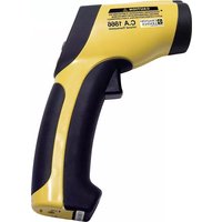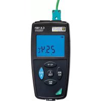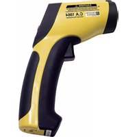
C.A 1864 - Thermometer CHAUVIN ARNOUX - Free user manual and instructions
Find the device manual for free C.A 1864 CHAUVIN ARNOUX in PDF.


User questions about C.A 1864 CHAUVIN ARNOUX
0 question about this device. Answer the ones you know or ask your own.
Ask a new question about this device
Download the instructions for your Thermometer in PDF format for free! Find your manual C.A 1864 - CHAUVIN ARNOUX and take your electronic device back in hand. On this page are published all the documents necessary for the use of your device. C.A 1864 by CHAUVIN ARNOUX.
USER MANUAL C.A 1864 CHAUVIN ARNOUX
text_image
SCAN HOLD E = 8.0 °C F 10 2 3 4 5 6 7 8 9text_image
Technical diagram of a mechanical device with numbered parts labeled ①, ②, and ③4.5 MESSAGES D'ERREUR
text_image
HOLD ε = 0,9 °C OL AVG 225.25.2 CONDITIONS CLIMATIQUES
text_image
Low battery indicator Open the battery cover 9v battery7.2 TEST DE FONCTIONNEMENT
C.A 1864....P01651813
C.A 1866....P01651814
Thank you for purchasing a C.A 1864 or C.A 1866 infrared thermometers.
To get the best service from this instrument:
- Read this user's manual carefully,
• Respect the safety precautions detailed
MEANING OF THE SYMBOL
 | Sorting of wastes required for the recycling of electrical and electronic equipment in the European Union.In accordance with directive WEEE 2002/96/EC: this equipment must not be processed as household waste. |
 | Possible danger. See explanations in this user manual |
 | Laser radiation, do not look into the LASER beam.LASER power < 1 mWWave length 630 - 670 mmClass II LASER |
If this device is damaged or a part is missing, please contact the dealer immediately.
The protection provided by the device may be compromised if it is used in a way not specified by the manufacturer.
Apply the safety tips listed below:
- Do not aim the LASER beam towards eyes.
- Do not place the thermometer on, or in proximity to, objects whose temperature is >65^ / 150^ .
- If the thermometer is subjected to great variations in ambient temperature, wait for 30 minutes after this becomes stable again before continuing with measurement, so as to attain the specified accuracy.
- Let condensation, which can build up on the lens of the thermometer's measurement aperture, dissipate before continuing with measurement.
- Do not subject the thermometer to strong electric or magnetic fields (e.g.: inductive heating, arc welding equipment...) that could induce errors in measurement.
- Respect the climatic environmental conditions
- Keep the lens perfectly clean.
SUMMARY
- PRESENTATION 20
- FUNCTIONING - EMISSIVITY 20
- DESCRIPTION 21
- USE 22
4.1 PROCEDURE....22
4.2 MEASUREMENT PRECAUTIONS 22
4.3 « TARGET DISTANCE / MEASUREMENT FIELD DIAMETER » RATIO ..... 23
4.4 MEASUREMENT PARAMETERS 24
4.5 ERROR MESSAGES 26
- SPECIFICATIONS 27
5.1 SPECIFICATIONS 27
5.2 CLIMATICS CONDITIONS....27
5.3 CONSTRUCTION SPECIFICATIONS....27
5.4 CONFORMITY TO INTERNATIONALS STANDARDS....27
- WARRANTY 28
- MAINTENANCE.... 28
7.1 MAINTENANCE 28
7.1.1 Battery replacement 28
7.2 WORKING TEST....28
7.3 CLEANING THE MEASUREMENT LENS 28
7.4 CLEANING THE CASING 29
7.5 METROLOGICAL SPECIFICATION....29
7.6 REPAIR....29
-
TO ORDER 29
-
ANNEXE 69
1. PRESENTATION
The C.A 1864 and C.A 1866 infrared thermometers are for the remote measurement of the temperature of most materials without physical contact, with an emissivity coefficient situated between 0.1 and 1.
They can also measure the temperature of polished metal surfaces after treatment (marking with opaque labels or mat spray paint) to limit the "mirror" reflexion effect of stray infrared ray interference. This treatment brings the emissivity coefficient to above 0.1 which ensures correct measurement. An emissivity table gives the emissivity ranges of a wide range of materials.
To measure a body's temperature, simply point the probe at its surface. The temperature displayed on the digital screen depends on the measurement parameter selected and on the emissivity chosen (according to material). The thermometer automatically switches off after 10 seconds.
2. FUNCTIONING - EMISSIVITY
All objects above absolute zero (-273.15°C) give out infrared energy. This radiated energy is emitted in all directions at the speed of light.
The instrument's lens picks up this energy and focuses it on an infrared detector. This detector gives a voltage signal proportional to the quantity of energy received and hence proportional to the temperature of the object.
Some objects not only give out infrared energy, but also reflect it as well. Unlike matt surfaces, brilliant or highly polished surfaces tend to reflect energy. This possible reflection is represented by a factor known as the emissivity, and can vary between 0.1 for a highly reflective surface, and 1 for a black body.
In the case of the C.A 1864 and C.A 1866 thermometers, the emissivity can be adjusted from 0.1 to 1, the value of which is determined depending on the material of the body or surface to be measured.
These thermometers are suited to measurements on varnished, anodised or oxidised surfaces, but taking into account their spectrum, shorter wavelength instruments are better adapted to measurements of brilliant surfaces. (see § Emissivity table).
To have a precise measurement, keep your thermometer perpendicularly to the target.
3. DESCRIPTION
text_image
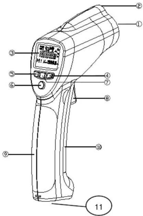
Technical diagram of a handheld device with numbered parts labeled for identification and assembly reference.1 : LASER view finder aperture
2 : Measurement lens
3 : LCD display
4 : S decrease in increments of emissivity values, hight and low value of the alarm
5 : r increase in increments of emissivity values, hight and low value of the alarm
6 : MODE : choice of measurement parameters through successive presses:
- EMI : emissivity percentage corresponding to the measurement
- MAX : maximum values as of switching on
- MIN : minimum values as of switching on
- DIF : temperature difference in relation to the reference value measured when switching on
- AVG : average of measured values
- HAL : hight value of the alarm
- LAL : low value of the alarm
7 : activation/deactivation of the LASER sight and back-lighting
8: On/start measurement trigger
9 : Handle Grip
10 : Battery housing cover
11: Standard mounting nut
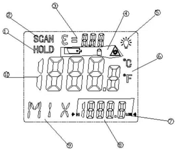
1 : holds the last measured value
2: Taking measurement
3 : Emissivity value
4 : Low battery indicator, lock function and laser
5 : Rétro éclairage actif
6 : measurement displayed in °C/°F
7 :Hight / low alert value indicator
8 : Temperature value MAX, MIN, DIF, AVG, HAL or LAL
9 : Actual setting : EMS, MAX, MIN, DIF, AVG, HAL or LAL
10 : Actual measured temperature value
text_image
SCAN HOLD Σ = 0.0 10 *°C *F M I X H 18 0.0 L0 ① ② ③ ④ ⑤ ⑥ ⑦ ⑧4. USE
Never aim the LASER beam towards eyes.
4.1 PROCEDURE
- Press the black trigger, all screen segments are displayed and the instrument carries out a measurement as set-up before it was last switched off. SCAN appeared on the screen. The HOLD symbol is displayed when you release the trigger and the main display holds the measurement until the automatic switch-off of the instrument after 10 seconds
- Press the trigger once more and set up the measurement parameters using the MODE button and possibly the buttons (see § 4.4).
- Activate or deactivate the LASER sight and backlighting.
- Aim the thermometer whilst pressing the trigger, using the LASER sight or otherwise, at the target to be measured (see § 4.2 and 4.3).
Note:
The instrument memorises the last measurement set-up when switched off, but not the last measurement.
If the trigger is held down, the instrument measures continuously.
4.2 MEASUREMENT PRECAUTIONS
- If the surface to be measured is frosted over or covered in other particles, if possible clean the surface so that it shows through and program in the corresponding emissivity value (see § 4.4).
- If the thermometer seems to give incorrect results, check the condition of the measurement lens for condensation or other particles that could be obstructing it. The lens should be cleaned carefully following the instructions in § 6.3.
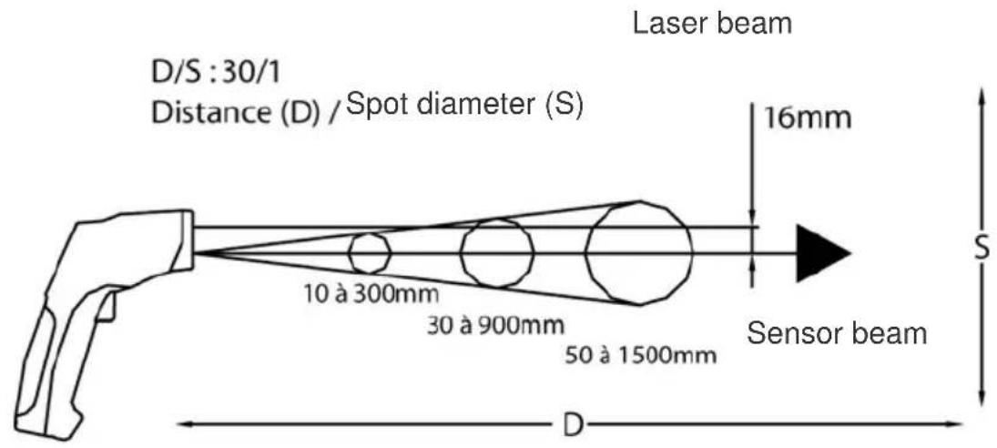
4.3 « TARGET DISTANCE / MEASUREMENT FIELD DIAMETER » RATIO
This ratio, also known as the field of vision, indicates the diameter of the probes' measurement field at a given distance from the target (see figure below).
C.A 1864
text_image
D/S : 30/1 Distance (D) / Spot diameter (S) Laser beam 16mm 10 à 300mm 30 à 900mm 50 à 1500mm Sensor beam S DC.A 1866
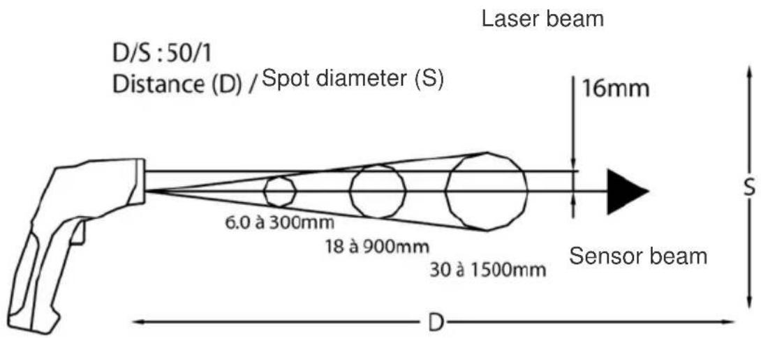
text_image
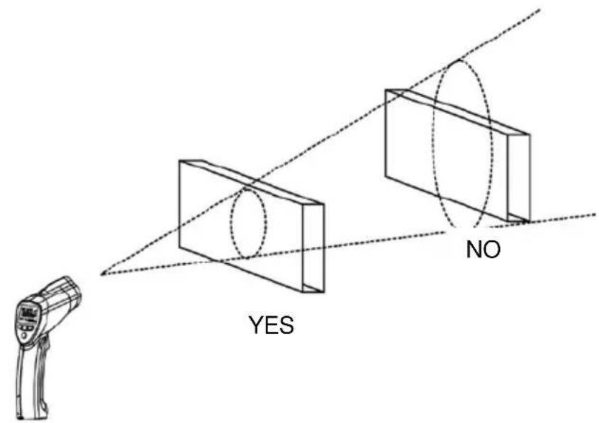
D/S : 50/1 Distance (D) / Spot diameter (S) Laser beam 16mm 6.0 à 300mm 18 à 900mm 30 à 1500mm Sensor beam D SIn the case of a measurement point of small dimensions, it is important to bring the probe to a short enough distance from the target, so as to avoid including other points into the field of measurement.
text_image
YES NO4.4 MEASUREMENT PARAMETERS
The choice and setting of the measurement parameters is carried out by successively pressing the MODE button:
■ EMI (see fig to right)
The emissivity percentage is adjusted using the buttons q p according to the surface being tested. (see table § 8.2).
Pressing the buttons q p briefly or holding them down for a longer period gives smaller or greater degrees of adjustment respectively. The setting is held in memory after the instrument is switched off and used during all successive measurements, whatever the parameter used.
■ MAX (see fig to right)
When the trigger is pressed and held, the small right-hand display indicates the maximum temperature value measured whilst the trigger is pressed.
The measurement set-up is held in memory after the instrument is switched off, but not the last maximum value recorded since the instrument takes into account the value measured upon the first press of the trigger when switching on.
HOLD = 0.9
°C
234.8
EMS
HOLD = 0.9
°C
234.8
MAX 300
■ MIN (see fig to right)
When the trigger is pressed and held, the small right-hand display indicates the minimum temperature value measured whilst the trigger is pressed.
The measurement set-up is held in memory after the instrument is switched off, but not the last minimum value recorded since the instrument takes into account the value measured upon the first press of the trigger when switching on.
■ DIF (see fig to right)
When the trigger is pressed and held, the small right-hand display indicates the temperature difference measured as of the start of measurement.
The measurement set-up is held in memory after the instrument is switched off, but not the last temperature difference value recorded since the instrument takes into account the value measured upon the first press of the trigger when switching on.
■ AVG (see fig to right)
When the trigger is pressed and held, the small right-hand display indicates the average temperature value measured whilst the trigger is pressed.
The measurement set-up is held in memory after the instrument is switched off, but not the last average value recorded since the instrument takes into account the value measured upon the first press of the trigger when switching on.
$$ \begin{array}{c} \text {HOLD} \ ^ {\circ} \mathrm{C} \end{array} \varepsilon = 0. 9 $$
$$ 2 3 4. 8 $$
$$ \text { MIN } \quad 1 0 $$
$$ \begin{array}{c} \text {HOLD} \ ^ {\circ} \mathrm{C} \end{array} \varepsilon = 0. 9 $$
$$ 2 3 4. 8 $$
$$ \begin{array}{c c} \text {DIF} & 0 2. 3 \end{array} $$
$$ \begin{array}{c c} \text {HOLD} & \varepsilon = 0, 9 \ ^ {\circ} \mathrm{C} \end{array} $$
$$ 2 3 4. 8 $$
$$ \text { AVG } \quad 2 2 5. 2 $$
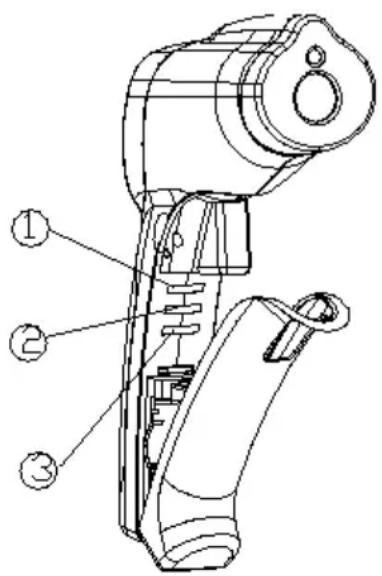
(1) C/F
Select the temperature units (°C or °F) using the °C/°F switch
(2) LOCK ON / OFF
To lock the unit on for continuous measurement, slide the middle switch LOCK ON/OFF right. If the trigger is pulled while the unit is lock on, the laser and backlight will turn on if they have been activated. When the unit is locked on, the backlight and laser will remain on unless it is turned off using the Laser/Backlight button on the keypad.
(3) SET ALARM
To activate the alarms, please slide the bottom switch SET ALARM right.
To set values for the High Alarm (HAL), Low Alarm (LAL), firstly active the display by pulling the trigger or press MODE, then press MODE until the appropriate code appears in the lower left corner of the display, press the UP and down buttons to adjust the desired values.
text_image
Technical diagram of a mechanical device with numbered parts labeled ①, ②, and ③4.5 ERROR MESSAGES
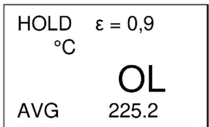
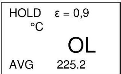
$$ \begin{array}{c c} \hline \text {HOLD} & \varepsilon = 0, 9 \ ^ {\circ} \mathrm{C} & \ & \text {OL} \ \text {AVG} & 2 2 5. 2 \ \hline \end{array} $$
Exceeding of the maximum value measurable
The maximum measurable value is 1000^ C / 1832 °F, which if exceeded causes the instrument to display the screen shown opposite.
$$ \boxed { \begin{array}{c c} \text {HOLD} & \varepsilon = 0, 9 \ ^ {\circ} \mathrm{C} & \ & - \text {OL} \ \text {AVG} & 2 2 5. 2 \end{array} } $$
Exceeding of the minimum value measurable
The minimum measurable value is -50^ / -58^ , which if exceeded causes the instrument to display the screen shown opposite.
5. SPECIFICATIONS
5.1 SPECIFICATIONS
• Measurement range: -50 to +1000°C (-58 to +1832°F)
• Resolution : 0,1°C/0,1°F
• Polarity indication : automatic (minus only)
- Accuracy :
-50 to -20^ (-58 to -4^ ): ±5^ ( ±9^ )
-20 to 200°C (-4 to 392 °F): ± 1.5% of the reading + 2 °C (±3.6 °F);
200 to 538°C (392 to 1000 °F): ± 2.0% of the reading +2 °C (±3.6 °F);
538 to 1000 °C (1000 to 1832 °F): ± 3.5% of the reading ± 5 °C (±9 °F)
• Field of view : 30/1 (C.A 1864) 50/1 (C.A 1866)
• Response time t 90 : < 1s
• Spectral response : 8 to 14μm
• Emissivity : adjustable from 0,1 to 1
• Screen lighting : adjustable by the user
- Measurement functions : normale, MAX, MIN, average value (AVG), difference between starting value (DIF), continuous measurement by locking on the measurement trigger, alert
• Power supply : 9V battery type 6LR61 or 6LF22
5.2 CLIMATICS CONDITIONS
In use: 0 to +50°C (32°F to 122°F), 10 to 90%HR
In storage: -20°C to +60°C (-4 to 140°F) < 80% HR
5.3 CONSTRUCTION SPECIFICATIONS
• Outside casing dimensions : 230 x 100 x 56mm
• Weight : 290g
5.4 CONFORMITY TO INTERNATIONALS STANDARDS
• Interference emissions : EN 55022 Classe B
• Interference stability : EN 50082-1
- LASER : Classe II
6. WARRANTY
Our guarantee is applicable for twelve months after the date on which the equipment is made available (extract from our General Conditions of Sale, available on request).
7. MAINTENANCE
For maintenance, use only specified spare parts. The manufacturer will not be held responsible for any accident occurring following a repair done other than by its After Sales Service or approved repairers.
7.1 MAINTENANCE
7.1.1 Battery replacement
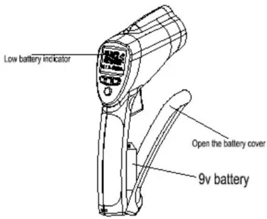
- As battery power is not sufficient, LCD will play “ ” replacement with one new battery type 9V is required.
- Open battery cover, then take out the battery from instrument and replace with a new 9-Volt battery
- Place the battery cover back.
text_image
Low battery indicator Open the battery cover 9v battery7.2 WORKING TEST
To check the good working order of thermometer, aim it towards water containing ice cubes, a simple 0^ C ( 32^ F) reference.
7.3 CLEANING THE MEASUREMENT LENS
- Remove dust with a clean pear-shaped dust removing syringe
- Carefully remove remaining particles using a clean and soft cloth.
• Delicately clean the lens using a damp cloth and leave to dry in air.
Do not use solvent
7.4 CLEANING THE CASING
Clean the casing with a cloth lightly dampened with soapy water. Rinse off with a damp cloth.
Do not use solvent.
7.5 METROLOGICAL SPECIFICATION
Like all measuring or testing devices, the instrument must be checked regularly.
This instrument should be checked at least once a year. For checking and calibration, contact one of our accredited metrology laboratories (information and contact details available on request), at our Chauvin Arnoux subsidiary or the branch in your country.
7.6 REPAIR
For all repairs before or after expiry of warranty, please return the device to your distributor.
8. TO ORDER
C.A 1864....P01651813
C.A 1866.....P01651814
Comes with a 9 V battery, a certificate of verification, a user's manual in a case.
Spares:
Battery....P01100620
Carrying case....P01298033
text_image
Labeled diagram of a handheld device with numbered parts and Chinese text annotationstext_image
SCAN HOLD E = 0.01 + - °C F ① ② ③ ④ ⑤ ⑥ ⑦ ⑧ ⑨4 ANWENDUNG
text_image
Technical diagram of a mechanical device with numbered components labeled ①, ②, and ③.4.5 FEHLERMELDUNGEN
HOLD ε = 0,9
°C
OL
AVG
225.2
HOLD ε = 0,9
°C
- OL
AVG
225.2
text_image
Low battery indicator Open the battery cover 9v batteryC.A 1864....P01651813
C.A 1866....P01651814
text_image
Diagram of a handheld device with numbered parts labeled for identification and labeling.text_image
SCAN HOLD E = 8.0 °C F 10 2 3 4 5 6 7 8 94. UTILIZZO
text_image
Technical diagram of a sewing machine with numbered parts labeled ①, ②, and ③4.5 MESSAGGI D'ERRORE
text_image
HOLD ε = 0,9 °C OL AVG 225.2text_image
Low battery Indicator Open the battery cover 9v batteryC.A 1864.....P01651813
C.A 1866.....P01651814
text_image
Labeled diagram of a handheld device with numbered parts and Chinese text annotationstext_image
SCAN HOLD E = 2.0°C F ① ② ③ ④ ⑤ ⑥ ⑦ ⑧ ⑨text_image
Technical diagram of a mechanical device with numbered parts labeled ①, ②, and ③4.5 MENSAJES DE ERROR
HOLD = 0,9
°C
OL
AVG
225.2
HOLD ε = 0,9
°C
- OL
AVG
225.2
text_image
Low battery indicator Open the battery cover 9v batteryNormally this table is adequate. Please, note that emissivity is also dependent on surface structure (e.g. coarseness).
Unit 1 Nelson Ct, Flagship Sq – Shaw Cross Business Pk
Dewsbury – West Yorkshire – WF12 7TH
Tel: 01924 460 494 - Fax: 01924 455 328
MIDDLE EAST - Chauvin Arnoux Middle East
P.O. BOX 60-154 - 1241 2020 JAL EL DIB (Beirut) - LEBANON
Tel: (01) 89 04 25 - Fax: (01) 89 04 24
CHINA - Shanghai Pu-Jiang - Enerdis Instruments Co. Ltd
3 F, 3 rd Building - N° 381 Xiang De Road - 200081 SHANGHAI
Tel: +86 21 65 21 51 96 - Fax: +86 21 65 21 61 07
USA - Chauvin Arnoux Inc - d.b.a AEMC Instruments
200 Foxborough Blvd. - Foxborough - MA 02035
Tel: (508) 698-2115 - Fax: (508) 698-2118
http://www.chauvin-arnoux.com