
BA312C - Air Conditioning BEKO - Free user manual and instructions
Find the device manual for free BA312C BEKO in PDF.

| Product type | Monobloc mobile air conditioner |
| Brand | Beko |
| Model | BA312C |
| Dimensions (packaged) | 515 x 443 x 880 mm (L x H x D) |
| Weight (packaged) | 36.2 kg |
| Power supply | 220-240 V ~ 50 Hz, single phase |
| Power consumption (cooling) | 1314 W |
| Cooling capacity | 3423 W (11680 BTU/h) |
| Energy efficiency (cooling) | 2.61 W/W (class A) |
| Refrigerant | R290 (propane), 210 g |
| Main functions | Cooling, Dehumidification, Ventilation, Auto, 24h Timer, Sleep, Automatic oscillation, Ionizer, Zone Follow |
| Fan speed | Low, Medium, High, Auto |
| Temperature range (cooling) | 17 °C to 30 °C |
| Maximum recommended area | Up to 28 m² (estimate) |
| Noise level | Not specified (estimate 50-60 dB) |
| Air filter | Washable, clean every 2 weeks |
| Condensate water tank | Manual drain or continuous hose drain |
| Remote control | Yes, range 8 m, AAA batteries included |
| Control panel | Built into unit (LED) |
| Included accessories | Window sliding kit, exhaust hose, adapters, foam seals, screws, remote control |
| Installation | Requires exhaust duct to outside |
| Safety | Gas leak protection, automatic full tank stop (code P1), automatic restart after power cut |
| Warranty | 2 years (standard) |
Frequently Asked Questions - BA312C BEKO
User questions about BA312C BEKO
0 question about this device. Answer the ones you know or ask your own.
Ask a new question about this device
Download the instructions for your Air Conditioning in PDF format for free! Find your manual BA312C - BEKO and take your electronic device back in hand. On this page are published all the documents necessary for the use of your device. BA312C by BEKO.
USER MANUAL BA312C BEKO
Local air conditioner
Instruction Manual
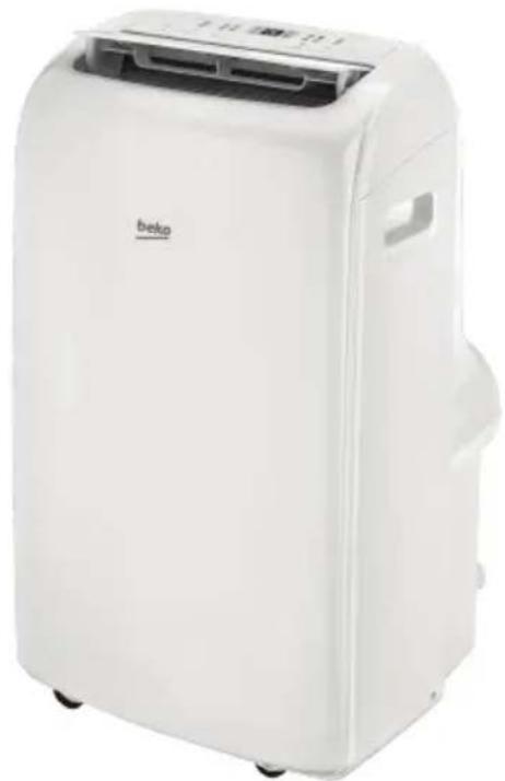
natural_image
White portable air conditioner unit with 'beko' branding and ventilation grille (no visible text or symbols beyond branding)BA 310 AC | BA 312 C BA 312 H
EN FR DE IT RO |
02M-8500063200-4920-01

Please read this user manual first!
Dear Customer,
Thank you for preferring a Beko product. We hope that you get the best results from your product which has been manufactured with high quality and state-of-the-art technology. Therefore, please read this entire user manual and all other accompanying documents carefully before using the product and keep it as a reference for future use. If you handover the product to someone else, give the user manual as well. Follow all warnings and information in the user manual.
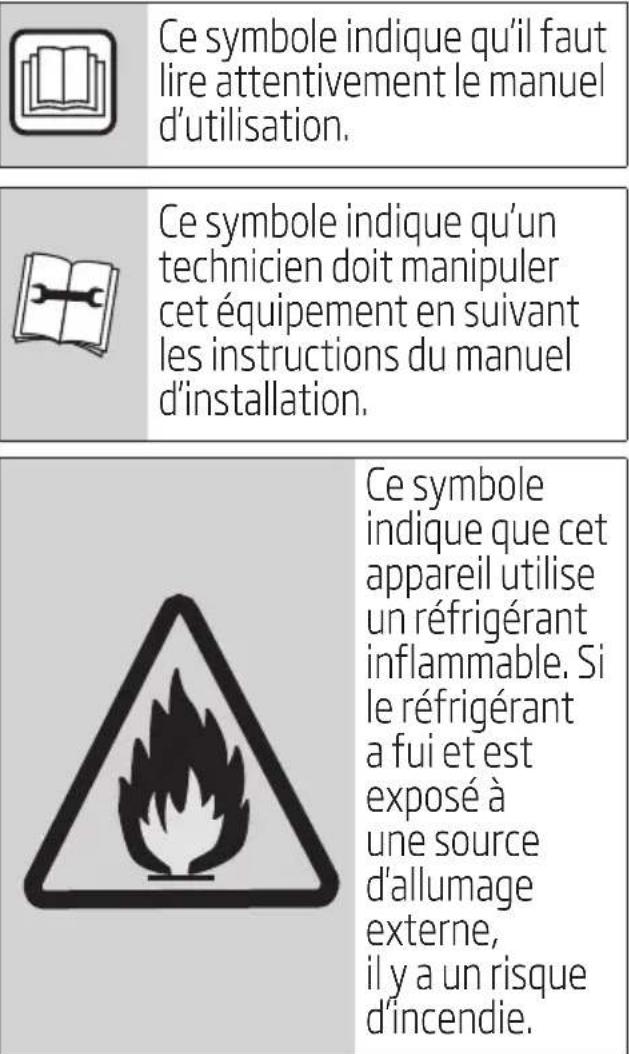
Meanings of the symbols
Following symbols are used in the various section of this manual:

Important information or useful hints about usage.

Warning for hazardous situations with regard to life and property.
Warning to actions that must never perform.
Warning for electric shock.
Warning for hot surfaces.
Do not cover it.

This symbol shows that the operation manual should be read carefully.
This symbol shows that a service personnel should be handling this equipment with reference to the installation manual.

This symbol shows that this appliance used a flammable refrigerant. If the refrigerant is leaked and exposed to an external ignition source, there is a risk of fire.

This product has been produced in environmentally friendly, modern facilities
Contents
1 Safety precautions 4
2 Warnings (for using R290 refrigerant only) 10
3 Preparation 22
4 Installation 24
4.1 Choosing.the.right location....24
4.2 Recommend installation 24
4.3 Tools needed....25
4.4 Accessories 25
4.5 Window installation kit....26
5 30operation
5.1 Operation instructions....33
5.2 Other features 35
6 3 Maintenance
6.1 Clean the air filter 38
7 4 Faults diagnosis
8 Design and compliance notes 41
9 Sociable remark 42
10 Installation instructions 43
10.1 F-Gas instruction....43
11 Specification
1 Safety precautions
Warning
To prevent death or injury to the user or other people and property damage, the following instructions must be followed. Incorrect operation due to ignoring of instructions may cause death, harm or damage.
Installation must be performed according to the installation instructions. Improper installation can cause water leakage, electrical shock, or fire.
Use only the included accessories and parts, and specified tools for the installation. Using non-standard parts can cause water leakage, electrical shock, fire, and injury or property damage.
Make sure that the outlet you are using is grounded and has the appropriate voltage. The power cord is equipped with a three-prong grounding plug to protect against shock. Voltage information can be found on the nameplate of the unit.
Your unit must be used in a properly grounded wall receptacle. If the wall receptacle you intend to use is not adequately grounded or protected by a time delay fuse or circuit breaker (the fuse or circuit breaker needed is determined by the maximum current of the unit. The maximum current is indicated on the nameplate located on unit), have a qualified electrician install the proper receptacle.
Install the unit on a flat, sturdy surface. Failure to do so could result in damage or excessive noise and vibration.
The unit must be kept free from obstruction to ensure proper function and to mitigate safety hazards.
1 Safety precautions
Do not modify the length of the power cord or use an extension cord to power the unit.
Do not share a single outlet with other electrical appliances. Improper power supply can cause fire or electrical shock.
- Do not install your air conditioner in a wet room such as a bathroom or laundry room. Too much exposure to water can cause electrical components to short circuit.
Do not install the unit in a location that may be exposed to combustible gas, as this could cause fire.
The unit has wheels to facilitate moving. Make sure not to use the wheels on thick carpet or to roll over objects, as these could cause tipping.
Do not operate a unit that it has been dropped or damaged.
The appliance with electric heater shall have at least 1 meter space to the combustible materials.
Do not touch the unit with wet or damp hands or when barefoot.
If the air conditioner is knocked over during use, turn off the unit and unplug it from the main power supply immediately. Visually inspect the unit to ensure there is no damage. If you suspect the unit has been damaged, contact a technician or customer service for assistance.
In a thunderstorm, the power must be cut off to avoid damage to the machine due to lightning.
Your air conditioner should be used in such a way that it is protected from moisture. e.g. condensation, splashed water, etc. Do not place
1 Safety precautions
or store your air conditioner where it can fall or be pulled into water or any other liquid. Unplug immediately if it occurs.
All wiring must be performed strictly in accordance with the wiring diagram located inside of the unit.
The unit's circuit board (PCB) is designed with a fuse to provide overcurrent protection. The specifications of the fuse are printed on the circuit board, such as: T 3.15A/250V, etc.
This appliance can be used by children aged from 8 years and above if they have been given supervision or instruction concerning use of the appliance in a safe way and understand the hazards involved. Cleaning and user maintenance shall not be made by children unless they are aged from 8 years and above and supervised. Keep the appliance and its cord out of reach of children aged less than 8 years. (be applicable for the European Countries).
This appliance is not intended for use by persons (including childern) with reduced physical, sensory or mental capabilities or lack of experience and knowledge, unless they have been given supervision or instruction concerning use of the appliance by a person responsible for their safety. (be applicable for other countries except the European Countries)
Children should be supervised to ensure that they do not play with the appliance. Children must be supervised around the unit at all times.
If the supply cord is damaged, it must be replaced by the manufacturer, its service agent or similarly qualified persons in order to avoid a hazard.
1 Safety precautions
Prior to cleaning or other maintenance, the appliance must be disconnected from the supply mains.
Do not remove any fixed covers. Never use this appliance if it is not working properly, or if it has been dropped or damaged.
Do not run cord under carpeting. Do not cover cord with throw rugs, runners, or similar coverings. Do not route cord under furniture or appliances. Arrange cord away from traffic area and where it will not be tripped over.
Do not operate unit with a damaged cord, plug, power fuse or circuit breaker. Discard unit or return to an authorized service facility for examination and/or repair.
To reduce the risk of fire or electric shock, do not use this appliance with any solid-state speed control device.
The appliance shall be installed in accordance with national wiring regulations.
Contact the authorised service technician for repair or maintenance of this unit.
Contact the authorised installer for installation of this unit.
Do not cover or obstruct the inlet or outlet grilles.
Do not use this product for functions other than those described in this instruction manual.
Before cleaning, turn off the power and unplug the unit.
- Disconnect the power if strange sounds, smell, or smoke comes from it.
1 Safety precautions
Do not press the buttons on the control panel with anything other than your fingers.
Do not remove any fixed covers. Never use this appliance if it is not working properly, or if it has been dropped or damaged.
Do not operate or stop the unit by inserting or pulling out the power cord plug.
Do not use hazardous chemicals to clean or come into contact with the unit. Do not use the unit in the presence of inflammable substances or vapour such as alcohol, insecticides, petrol, etc.
Always transport your air conditioner in a vertical position and stand on a stable, level surface during use.
Always contact a qualified person to carry out repairs. If the damaged power supply cord must be replaced with a new power supply cord obtained from the product manufacturer and not repaired.
Hold the plug by the head of the power plug when taking it out.
Turn off the product when not in use.
Warning Do not use manuals to accelerate the defrosting process or to clean, other than those recommended by the manufacturer. The appliance shall be stored in a room without Continuously operation ignition sources (for example: open flames, an operation gas appliance or an operating electric heater.) Do not pierce or burn. Be aware that refrigerants may not contain an odour.
The appliance shall state the insulation of a residual current device (RCD) having rated residual operating current not exceeding 30mA.
1 Safety precautions
This appliance is intended to be used in household and similar applications such as
- Staff kitchen areas in shops, offices and other working environments;
- farm houses;
- by clients in hotels, motels and other residential type environments;
- bed and breakfast type environments;
2 Warnings (for using R290 refrigerant only)
Do not use means to accelerate the defrosting process or to clean, other than those recommended by the manufacturer.
The appliance shall be stored in a room without continuously operating ignition sources (for example: open flames, an operating gas appliance or an operating electric heater).
Do not pierce or burn.
Be aware that the refrigerants may not contain an odour.
Appliance BA 09 C / BA 10 AC, should be installed, operated and stored in a room with a floor area larger than 10 m².
Appliance BA 12 C / BA 12 H, should be installed, operated and stored in a room with a floor area larger than 12 m^2 .
Compliance with national gas regulations shall be observed.
Keep ventilation openings clear of obstruction.
The appliance shall be stored so as to prevent mechanical damage from occurring.
A warning that the appliance shall be stored in a well-ventilated area where the room size corresponds to the room area as specified for operation.
Any person who is involved with working on or breaking into a refrigerant circuit should hold a current valid certificate from an industry-accredited assessment authority, which authorises their competence to handle refrigerants safely in accordance with an industry recognised assessment specification.
2 Warnings (for using R290 refrigerant only)
Servicing shall only be performed as recommended by the equipment manufacturer. Maintenance and repair requiring the assistance of other skilled personnel shall be carried out under the supervision of the person competent in the use of flammable refrigerants.
-
Transport of equipment containing flammable refrigerants. See transport regulations.
-
Marking of equipment using signs. See local regulations.
-
Disposal of equipment using flammable refrigerants. See national regulations.
-
Storage of equipment/appliances The storage of equipment should be in accordance with the manufacturer's instructions.
-
Storage of packed (unsold) equipment Storage package protection should be constructed such that mechanical damage to the equipment inside the package will not cause a leak of the refrigerant charge. The maximum number of pieces of equipment permitted to be stored together will be determined by local regulations.
-
Information on servicing 1) Checks to the area
Prior to beginning work on systems containing flammable refrigerants, safety checks are necessary to ensure that the risk of ignition is minimised. For repair to the refrigerating system, the
2 Warnings (for using R290 refrigerant only)
following precautions shall be complied with prior to conducting work on the system.
2) Work procedure
Work shall be undertaken under a controlled procedure so as to minimise the risk of a flammable gas or vapour being present while the work is being performed.
3) General work area
All maintenance staff and others working in the local area shall be instructed on the nature of work being carried out. Work in confined spaces shall be avoided. The area around the workspace shall be sectioned off. Ensure that the conditions within the area have been made safe by control of flammable material.
4) Checking for presence of refrigerant
The area shall be checked with an appropriate refrigerant detector prior to and during work, to ensure the technician is aware of potentially flammable atmospheres. Ensure that the leak detection equipment being used is suitable for use with flammable refrigerants, i.e. non-sparking, adequately sealed or intrinsically safe.
5) Presence of fire extinguisher
If any hot work is to be conducted on the refrigeration equipment or any associated parts, appropriate fire extinguishing equipment shall be available to hand. Have a dry powder or CO_2 fire extinguisher adjacent to the charging area.
2 Warnings (for using R290 refrigerant only)
6) No ignition sources
No person carrying out work in relation to a refrigeration system which involves exposing any pipe work that contains or has contained flammable refrigerant shall use any sources of ignition in such a manner that it may lead to the risk of fire or explosion. All possible ignition sources, including cigarette smoking, should be kept sufficiently far away from the site of installation, repairing, removing and disposal, during which flammable refrigerant can possibly be released to the surrounding space. Prior to work taking place, the area around the equipment is to be surveyed to make sure that there are no flammable hazards or ignition risks. No Smoking signs shall be displayed.
7) Ventilated area
Ensure that the area is in the open or that it is adequately ventilated before breaking into the system or conducting any hot work. A degree of ventilation shall continue during the period that the work is carried out. The ventilation should safely disperse any released refrigerant and preferably expel it externally into the atmosphere.
8) Checks to the refrigeration equipment
Where electrical components are being changed, they shall be fit for the purpose and to the correct specification. At all times the manufacturer's maintenance and service guidelines shall be followed. If in doubt consult the manufacturer's technical department for assistance. The following checks shall be applied to installations using flammable refrigerants:
2 Warnings (for using R290 refrigerant only)
The charge size is in accordance with the room size within which the refrigerant containing parts are installed;
The ventilation machinery and outlets are operating adequately and are not obstructed;
If an indirect refrigerating circuit is being used, the secondary circuit shall be checked for the presence of refrigerant; Marking to the equipment continues to be visible and legible. Markings and signs that are illegible shall be corrected;
Refrigeration pipe or components are installed in a position where they are unlikely to be exposed to any substance which may corrode refrigerant containing components, unless the components are constructed of materials which are inherently resistant to being corroded or are suitably protected against being so corroded.
9) Checks to electrical devices
Repair and maintenance to electrical components shall include initial safety checks and component inspection procedures. If a fault exists that could compromise safety, then no electrical supply shall be connected to the circuit until it is satisfactorily dealt with. If the fault cannot be corrected immediately but it is necessary to continue operation, an adequate temporary solution shall be used. This shall be reported to the owner of the equipment so all parties are advised.
Initial safety checks shall include:
That capacitors are discharged: this shall be done in a safe manner to avoid possibility of sparking;
2 Warnings (for using R290 refrigerant only)
That there no live electrical components and wiring are exposed while charging, recovering or purging the system;
That there is continuity of earth bonding.
7. Repairs to sealed components
1) During repairs to sealed components, all electrical supplies shall be disconnected from the equipment being worked upon prior to any removal of sealed covers, etc. If it is absolutely necessary to have an electrical supply to equipment during servicing, then a permanently operating form of leak detection shall be located at the most critical point to warn of a potentially hazardous situation.
2) Particular attention shall be paid to the following to ensure that by working on electrical components, the casing is not altered in such a way that the level of protection is affected. This shall include damage to cables, excessive number of connections, terminals not made to original specification, damage to seals, incorrect fitting of glands, etc.
Ensure that apparatus is mounted securely.
Ensure that seals or sealing materials have not degraded such that they no longer serve the purpose of preventing the ingress of flammable atmospheres. Replacement parts shall be in accordance with the manufacturer's specifications.

Note:
The use of silicon sealant may inhibit the effectiveness of some types of leak detection equipment. Intrinsically safe components do not have to be isolated prior to working on them.
2 Warnings (for using R290 refrigerant only)
8. Repair to intrinsically safe components
Do not apply any permanent inductive or capacitance loads to the circuit without ensuring that this will not exceed the permissible voltage and current permitted for the equipment in use. Intrinsically safe components are the only types that can be worked on while live in the presence of a flammable atmosphere. The test apparatus shall be at the correct rating. Replace components only with parts specified by the manufacturer. Other parts may result in the ignition of refrigerant in the atmosphere from a leak.
9. Cabling
Check that cabling will not be subject to wear, corrosion, excessive pressure, vibration, sharp edges or any other adverse environmental effects. The check shall also take into account the effects of aging or continual vibration from sources such as compressors or fans.
10. Detection of flammable refrigerants
Under no circumstances shall potential sources of ignition be used in the searching for or detection of refrigerant leaks. A halide torch (or any other detector using a naked flame) shall not be used.
11. Leak detection methods
The following leak detection methods are deemed acceptable for systems containing flammable refrigerants. Electronic leak detectors shall be used to detect flammable refrigerants, but the sensitivity may not be adequate, or may need re-calibration. (Detection equipment shall be calibrated in a refrigerant-free area.) Ensure that the detector is not a potential source of ignition
2 Warnings (for using R290 refrigerant only)
and is suitable for the refrigerant used. Leak detection equipment shall be set at a percentage of the LFL of the refrigerant and shall be calibrated to the refrigerant employed and the appropriate percentage of gas (25 % maximum) is confirmed. Leak detection fluids are suitable for use with most refrigerants but the use of detergents containing chlorine shall be avoided as the chlorine may react with the refrigerant and corrode the copper pipe-work. If a leak is suspected, all naked flames shall be removed/ extinguished. If a leakage of refrigerant is found which requires brazing, all of the refrigerant shall be recovered from the system, or isolated (by means of shut off valves) in a part of the system remote from the leak. Oxygen free nitrogen (OFN) shall then be purged through the system both before and during the brazing process.
12. Removal and evacuation
When breaking into the refrigerant circuit to make repairs or for any other purpose conventional procedures shall be used. However, it is important that best practice is followed since flammability is a consideration. The following procedure shall be adhered to:
Remove refrigerant;
• Purge the circuit with inert gas;
Evacuate;
•Purge again with inert gas;
●pen the circuit by cutting or brazing.
The refrigerant charge shall be recovered into the correct recovery cylinders. The system shall be flushed with OFN to render the
2 Warnings (for using R290 refrigerant only)
unit safe. This process may need to be repeated several times.
Compressed air or oxygen shall not be used for this task.
Flushing shall be achieved by breaking the vacuum in the system with OFN and continuing to fill until the working pressure is achieved, then venting to atmosphere, and finally pulling down to a vacuum. This process shall be repeated until no refrigerant is within the system. When the final OFN charge is used, the system shall be vented down to atmospheric pressure to enable work to take place. This operation is absolutely vital if brazing operations on the pipe-work are to take place. Ensure that the outlet for the vacuum pump is not close to any ignition sources and there is ventilation available.
13. Charging procedures
In addition to conventional charging procedures, the following requirements shall be followed. Ensure that contamination of different refrigerants does not occur when using charging equipment. Hoses or lines shall be as short as possible to minimise the amount of refrigerant contained in them.
Cylinders shall be kept upright.
Ensure that the refrigeration system is earthed prior to charging the system with refrigerant.
Label the system when charging is complete (if not already).
Extreme care shall be taken not to overfill the refrigeration system. Prior to recharging the system it shall be pressure tested with OFN. The system shall be leak tested on completion of charging but prior to commissioning. A follow up leak test shall be carried out prior to leaving the site.
2 Warnings (for using R290 refrigerant only)
14. Decommissioning
Before carrying out this procedure, it is essential that the technician is completely familiar with the equipment and all its detail. It is recommended good practice that all refrigerants are recovered safely. Prior to the task being carried out, an oil and refrigerant sample shall be taken in case analysis is required prior to re-use of reclaimed refrigerant. It is essential that electrical power is available before the task is commenced.
a. Become familiar with the equipment and its operation.
b. Isolate system electrically.
c. Before attempting the procedure ensure that:
Mechanical handling equipment is available, if required, for handling refrigerant cylinders;
All personal protective equipment is available and being used correctly; The recovery process is supervised at all times by a competent person;
Recovery equipment and cylinders conform to the appropriate standards.
d. Pump down refrigerant system, if possible.
e. If a vacuum is not possible, make a manifold so that refrigerant can be removed from various parts of the system.
f. Make sure that cylinder is situated on the scales before recovery takes place.
g. Start the recovery machine and operate in accordance with manufacturer's instructions.
2 Warnings (for using R290 refrigerant only)
h. Do not overfill cylinders. (No more than 80 % volume liquid charge).
i. Do not exceed the maximum working pressure of the cylinder, even temporarily.
j. When the cylinders have been filled correctly and the process completed, make sure that the cylinders and the equipment are removed from site promptly and all isolation valves on the equipment are closed off.
k. Recovered refrigerant shall not be charged into another refrigeration system unless it has been cleaned and checked.
- Labelling
Equipment shall be labelled stating that it has been decommissioned and emptied of refrigerant. The label shall be dated and signed. Ensure that there are labels on the equipment stating the equipment contains flammable refrigerant.
- Recovery
When removing refrigerant from a system, either for servicing or decommissioning, it is recommended good practice that all refrigerants are removed safely.
When transferring refrigerant into cylinders, ensure that only appropriate refrigerant recovery cylinders are employed.
Ensure that the correct number of cylinders for holding the total system charge is available. All cylinders to be used are designated for the recovered refrigerant and labelled for that refrigerant (i.e. special cylinders for the recovery of refrigerant). Cylinders shall be complete
2 Warnings (for using R290 refrigerant only)
with pressure relief valve and associated shut-off valves in good working order.
Empty recovery cylinders are evacuated and, if possible, cooled before recovery occurs.
The recovery equipment shall be in good working order with a set of instructions concerning the equipment that is at hand and shall be suitable for the recovery of flammable refrigerants. In addition, a set of calibrated weighing scales shall be available and in good working order. Hoses shall be complete with leak-free disconnect couplings and in good condition. Before using the recovery machine, check that it is in satisfactory working order, has been properly maintained and that any associated electrical components are sealed to prevent ignition in the event of a refrigerant release. Consult manufacturer if in doubt.
The recovered refrigerant shall be returned to the refrigerant supplier in the correct recovery cylinder, and the relevant Waste Transfer Note arranged. Do not mix refrigerants in recovery units and especially not in cylinders. If compressors or compressor oils are to be removed, ensure that they have been evacuated to an acceptable level to make certain that flammable refrigerant does not remain within the lubricant. The evacuation process shall be carried out prior to returning the compressor to the suppliers. Only electric heating to the compressor body shall be employed to accelerate this process. When oil is drained from a system, it shall be carried out safely.
3 Preparation
3 Preparation
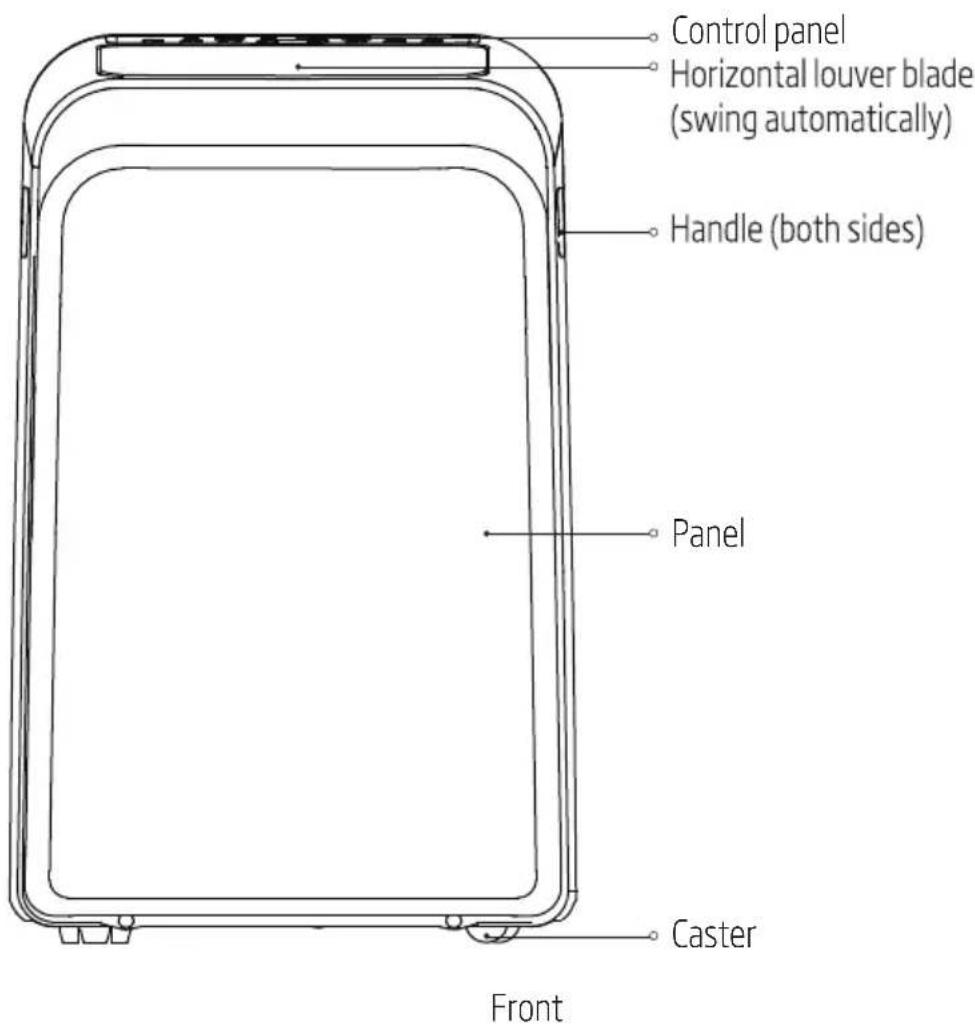
- Upper air filter (behind the grille)
- Upper air intake
- Drain outlet
- Air outlet
- lower air filter
-
Lower air intake
-
Drain outlet (only for pump heating mode)
- Power cord buckle
- Power cord outlet
- Power plug socket
- Bottom tray drain outlet
Rear
4 Installation
4.1 Choosing the right location
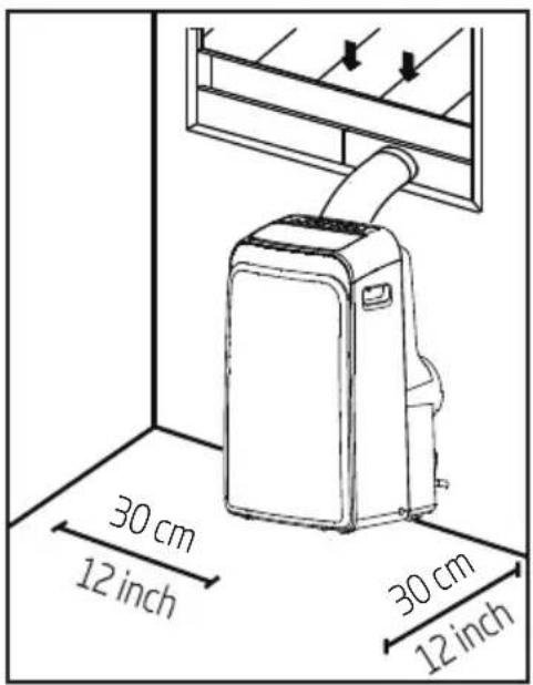
Your installation location should meet the following requirements:
- Make sure that you install your unit on an even surface to minimize noise and vibration.
- The unit must be installed near a grounded plug, and the collection tray drain (found on the back of the unit) must be accessible.
- The unit should be located at least 30 cm (12") from the nearest wall to ensure proper air conditioning.
- Do not cover the Intakes, outlets or remote signal receptor of the unit, as this could cause damage to the unit.
4.2 Recommend installation
4 Installation

Note:
All the illustrations in the manual are for explanation purpose only. Your machine may be slightly different.
The unit can be controlled by the unit control panel alone or with the remote controller. This manual does not include Remote controller operations, see the << Remote Controll Illustration >> packed with the unit for details.
When there are wide differences between "Instruction manual" and "Remote control Illustration" on function description, the description on "Instruction manual" shall prevail.
4.3 Tools needed
- Medium Philips screwdriver; -Tape measure or ruler; -Knife or scissors; -Saw (optional, to shorten window adaptor for narrow windows)
4.4 Accessories
Check your window size and choose the fit window slider.
| Parts | Description | Quantity |
 | Unit adaptor | 1 pc |
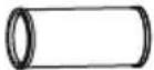 | Exhaust Hose 1 pc | |
 | Window Slider Adaptor | 1 pc |
| [WDHS] | Wall Exhaust Adaptor A(only for wall installation) | 1 pc |
 | Wall Exhaust Adaptor B (with cap)(only for wall installation) | 1 pc |
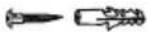 | Screw and anchor(only for wall installation) | 4 set |
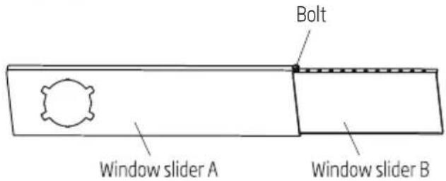
 | Window Slider A | 1 pc |
 | Window Slider B | 1 pc |
 | Power Cord Buckle 1 pc |
4 Installation
| Parts | Description | Quantity |
 | Bolt 1 pc | |
 | Security Bracket and Screw | 1 set |
 | Drain Hose | 1 pc |
 | Drain Hose Adaptor (only for heat pump mode) | 1 pc |
 | Foam Seal A (Adhesive) | 2 pc |
 | Foam Seal B (Adhesive) | 2 pc |
 | Foam Seal C (Non-adhesive) | 1 pc |
 | Remote Controller and Battery 1 set |
4.5 Window installation kit
Step one: Preparing the exhaust hose assembly
press the exhaust hose into the window slider adaptor and unit adaptor, clamp automatically by elastic buckles of the adaptors.
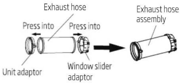
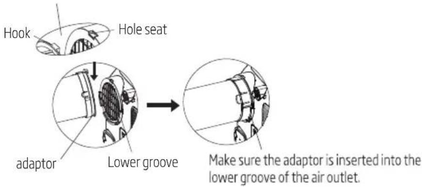
Step two: Install the exhaust hose assembly to the unit
Insert unit adaptor of the exhaust hose assembly into the lower groove of the air outlet of the unit while the hook of the adaptor is aligned with the hole seat of the air outlet and slide down the exhaust hose assembly along the arrow direction for installation.
4 Installation
Make sure the hook of the adaptor is aligned with the hole seat of the air outlet.
Step three: Preparing the adjustable window slider
Depending on the size of your window, adjust the size of the window slider.

Note: Once the exhaust hose assembly and adjustable window slider are prepared, choose from one of the following installation methods.
Type 1: Hung window or sliding window installation (optional)
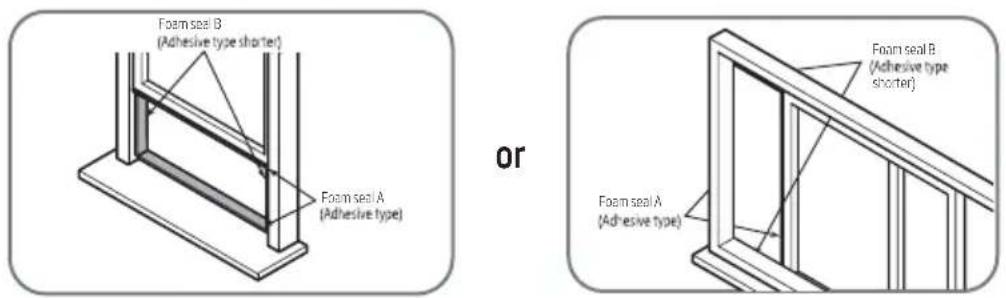
4 Installation
- Cut the adhesive foam seal A and B strips to the proper lengths, and attach them to the window sash and frame as shown.
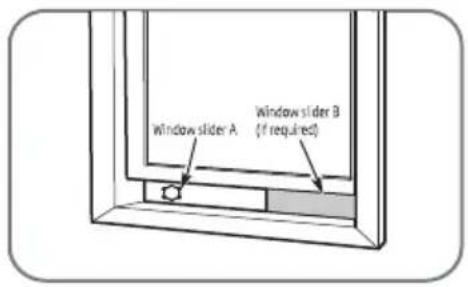
or
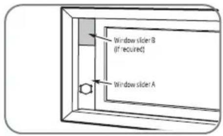
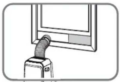
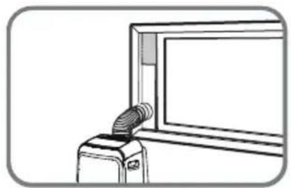
- Insert the window slider assembly into the window opening.
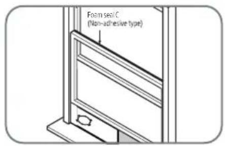
or
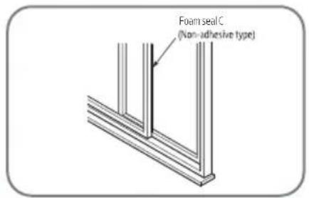
- Cut the non-adhesive foam seal C strip to match the width of the window. Insert the seal between the glass and the window frame to prevent air and insects from getting into the room.
or
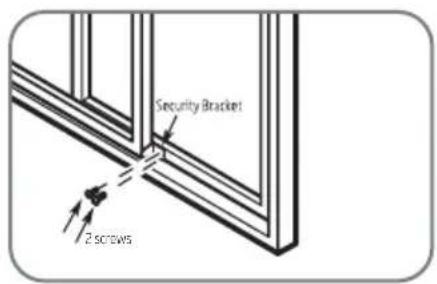
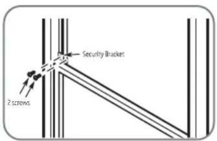
- If desired, install the security bracket with 2 screws as shown.
natural_image
Line drawing of a vacuum cleaner emitting a hose, mounted on a stand (no text or symbols)or
natural_image
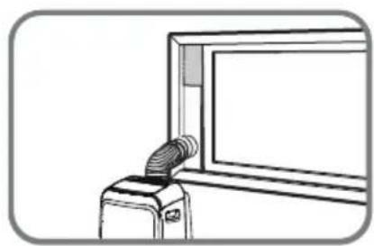
Line drawing of a device with a coiled cable inserted into a window (no text or symbols)- Insert the window slider adaptor into the hole of the window slider.
4 Installation
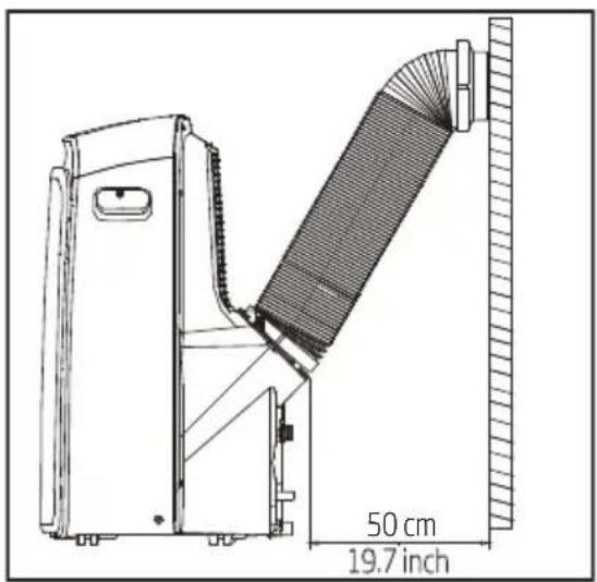
Type 2: Wall installation (optional)
- Cut a 125mm (4.9inch) hole into the wall for the wall exhaust adaptor B. 2. Secure the wall exhaust adaptor B to the wall using the four anchors and screws provided in the kit. 3. Connect the exhaust hose Assembly(with wall exhaust adaptor A) to the Wall exhaust adaptor B.
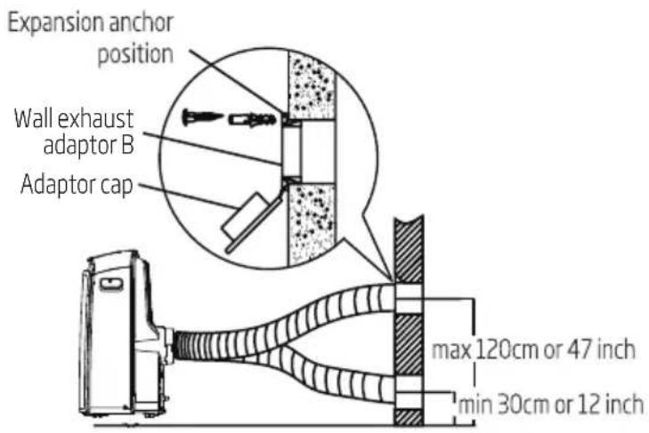

Note: Cover the hole using the adaptor cap when not in use.

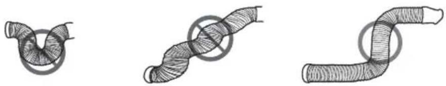
Note: To ensure proper function, do not overextend or bend the hose. Make sure that there is no obstacle around the air outlet of the exhaust hose (in the range of 500mm) in order to the exhaust system works properly. All the illustrations in this manual are for explanation purpose only. Your air conditioner may be slightly different. The actual shape shall prevail.
natural_image
Three hand-drawn illustrations of coiled pipes with no text or symbols5 Operation

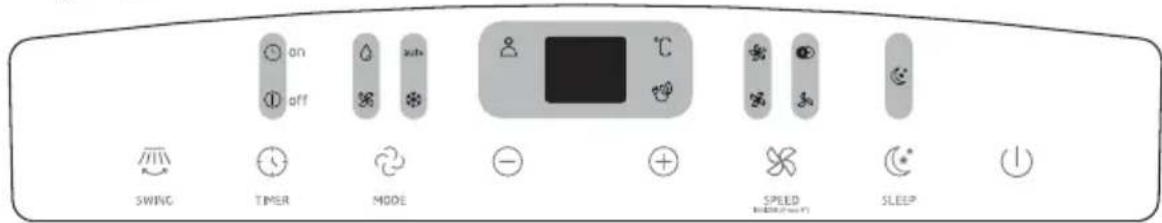
Note: The control panel will look like following:
For heat pump models
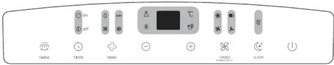
For cooling only models
| Heat mode light | High fan speed light | Zone follow light | |||
| Cool mode light | Med fan speed light | Sleep light | |||
| Fan mode light | Low fan speed light | °C | Degrees celsius | ||
| Dry mode light | auto | Auto mode light | LED display | ||
| Ionizer |
SWING button
Used to initiate the Auto swing feature. When the operation is On, press the SWING button can stop the louver at the desired angle.
5 Operation
TIMER button
Used to initiate the Auto on start time and Auto off stop time program, in conjunction with the + & - buttons. The timer on/off indicator light illuminates under the timer on/off settings.
MODE button
Selects the appropriate operating mode. Each time you press the button, a mode is selected in a sequence that goes from Auto), Cool, Dry, Fan and Heat (cooling only models without). The mode indicator light illuminates under the different mode settings.
Up (+) and Down (-) buttons
Used to adjust (increasing/decreasing) temperature settings in 1°C increments in a range of 17°C to 30°C or the Timer setting in a range of 0-24hrs.

Note: The control is capable of displaying temperature in degrees Celsius. To convert from one to the other, press and hold the Up and Down buttons at the same time for 3 seconds.
FAN
Control the fan speed. Press to select the fan speed in four steps-Low, Med, High and Auto. The fan speed indicator light illuminates under different fan settings. When select Auto fan speed, all the fan indicator lights turn dark.
SLEEP button
Used to initiate the Sleep operation.
Power button
Power switch on/off.
LED display
Shows the set temperature in °C and the Auto-timer settings. While on Dry and Fan modes, it shows the room temperature.
Shows Error codes and protection code:
E1-Room temperature sensor error.
E2-Evaporator temperature sensor error.
E3-Condenser temperature sensor error (on some models).
E4-Display panel communication error.
P1-Bottom tray is full--Connect the drain hose and drain the collected water away. If protection repeats, call for service.
5 Operation
IONIZER feature
Press SPEED button for 3 seconds to initiate IONIZER feature and the IONIZER light illuminates, the LED display shows 'ON' for 3 seconds. The ion generator is energized and will help to purify the air inside. Press SPEED button for 3 seconds again to stop the IONIZER feature and the IONIZER light turn dark, the LED display shows 'OF' for 3 seconds.
Note:
- When the function is turned on, it will continuous working until you turn off the function or product.
5 Operation

Note: When one of the above malfunctions occurs, turn off the unit, and check for any obstructions. Restart the unit, if the malfunction is still present, turn off the unit and unplug the power cord. Contact the manufacturer or its service agents or a similar qualified person for service.
Exhaust hose installation
The exhaust hose and adaptor must be installed or removed in accordance with the usage mode. For Cool, Heat (heat pump type) or Auto mode must be installed exhaust hose.
For fan, dehumidIfy or heat (electrical heat type) mode must be removed exhaust hose.
5.1 Operation instructions
Cool operation
- Press the "MODE" button until the "Cool" indicator light comes on.
- Press the Adjust buttons "+" or "-" to select your desired room temperature. The temperature can be set within a range of 17°C-30°C.
- Press the "FAN SPEED" button to choose the fan speed.
Heat operation (cooling only models without this function)
- Press the "MODE" button until the "Heat" indicator light comes on.
- Press the Adjust buttons "+" or "-" to select your desired room temperature. The temperature can be set within a range of 17°C-30°C.
- Press the "FAN SPEED" button to choose the fan speed. For some models, the fan speed can not be adjusted under Heat mode.
Dry operation
- Press the "MODE" button until the "Dry" indicator light comes on.
- Under this mode, you cannot select a fan speed or adjust the temperature. The fan motor operates at Low speed.
- Keep windows and doors closed for the best dehumidifying effect.
- Do not put the duct to window.
Auto operation
- When you set the air conditioner in Auto mode, it will automatically select cooling, heating (cooling only models without), or fan only operation depending on what temperature you have selected and the room temperature.
- The air conditioner will control room temperature automatically round the temperature point set by you.
- Under Auto mode, you can not select the fan speed.
5 Operation

Note: Under Auto mode, both the Auto mode and the actual operation mode indicator lights illuminate for some models.
Fan operation
- Press the "MODE" button until the "Fan" indicator light comes on.
- Press the "FAN SPEED" button to choose the fan speed. The temperature can not be adjusted.
- Do not put the duct to window.
Timer operation
- When the unit is on, press the TIMER button will initiate the Auto-off stop program, the Timer off indicator light illuminates. Press the up or down button to select the desired time. Press the Timer button again within 5 seconds, the Auto-on start program is initiated. And the Timer on indicator light illuminates. Press the up or down button to select the desired Auto-on start time.
- When the unit is off, press the Timer button to initiate the Auto-on start program, press it again within 5 seconds will initiate the Auto-off stop program.
- Press or hold the Up or Down button to change the Auto time by 0.5 hour increments, up to 10 hours, then at 1 hour increments up to 24 hours. The control will count down the time remaining until start.
- The system will automatically revert back to display the previous temperature setting if there is no operation in a 5 seconds period.
- Turning the unit On or Off at any time or adjusting the timer setting to 0.0 will cancel the Auto Start/Stop timer program.
Sleep (Eco) operation
-Press this button, the selected temperature will increase (cooling) or decrease(heating) by 1°C 30 minutes. The temperature will then increase (cooling) or decrease (heating) by another 1°C after an additional 30 minutes. This new temperature will be maintained for 7 hours before it returns to the originally selected temperature. This ends the Sleep mode and the unit will continue to operate as originally programmed.

Note: This feature is unavailable under Fan or Dry mode.
5 Operation
5.2 Other features
Zone follow

Note: This feature can be activated from the remote control only. The remote control serves as a remote thermostat allowing for the precise temperature control at its location. To activate the Zone Follow feature, point the remote control towards the unit and press the Zone Follow. The remote control will send this signal to the air conditioner until press the Zone Follow again. If the unit does not receive the Zone Follow/Temp Sensing signal during any 7 minutes interval, the unit will exit the Zone Follow/Temp Sensing mode.

Note: This feature is unavailable under Fan or Dry mode.
Auto-Restart
If the unit breaks off unexpectedly due to the power cut, it will restart with the previous function setting automatically when the power resumes.
Air flow direction adjustment
The louver can be adjusted automatically. Adjust the air flow direction automatically:
- When the power is on, the louver opens fully.
- Press the SWING button on the panel or remote controller to initiate the Auto swing feature. The louver will! swing up and down automatically.
- Please do not adjust the louver manually.
Wait 3 minutes before resuming operation
After the unit has stopped, it can not be restarted operation in the first 3 minutes. This is to protect the unit. Operation will automatically start after 3 minutes.
Power management feature (on some models)
When the ambient temperature is lower than the setting temperature for a period of time, the unit will be automatically operate power management feature. The compressor and fan motor stop. When the ambient temperature is higher than the setting temperature, the unit will be automatically quit the power management feature. The compressor and (or) fan motor run.

Note: For unit with power management light, the light will illuminate under this feature.
5 Operation
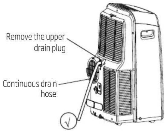
Water drainage
- During dehumidifying modes, remove the upper drain plug from the back of the unit, install the drain connector (5/8" universal female mender) with 3/4" hose (locally purchased). For the models without drain connector, just attach the drain hose to the hole. Place the open end of the hose directly over the drain area in your basement floor.
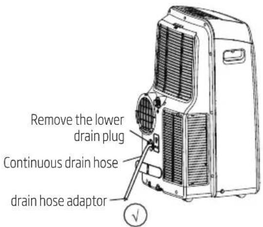
- During heating pump mode, remove the lower drain plus from the back of the unit, install the drain connector (5/8" universal female mender) with 3/4" hose (locally purchased). For the models without drain connector, just attach the drain hose to the hole. Place the open end of the Hose adaptor directly over the drain area in your basement floor.

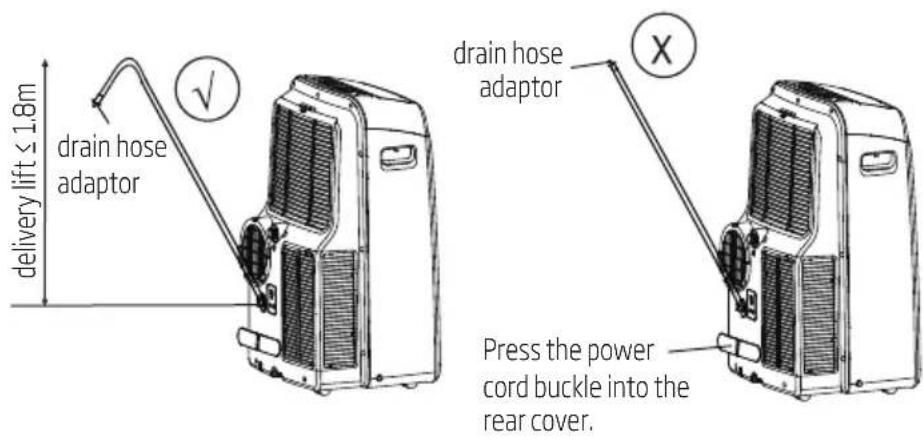
Note: Make sure the hose is secure so there are no leaks. Direct the hose toward the drain, making sure that there are no kinks that will stop the warter flowing. Place the end of the hose into the drain and make sure the end of the hose is down to let the water flow smoothly. (See figs with √. Do never let it up. (See figs with ✗When the continuous drain hose is not used, ensure that the corresponding drain plug and knob are installed firmly to prevent leakage.
5 Operation
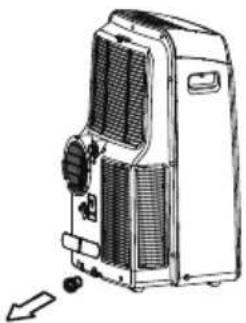
- When the water level of the bottom tray reaches a predetermined level, the unit beeps 8 times, the digital display area shows "P1". At this time the air conditioning/dehumidification process will immediately stop. However, the fan motor will continue to operate(this is normal). Carefully move the unit to a drain location, remove the bottom drain plug and let the water drain away. Reinstall the bottom drain plug and restart the machine until the "P1" symbol disappears. If the error repeats, call for service.

Note: Be sure to reinstall the bottom drain plug firmly to prevent leakage before using the unit.
natural_image
Line drawing of a portable air conditioner unit with cooling fins and buttons (no text or symbols)6 Maintenance

Warning:
- Always unplug the unit before cleaning or servicing.
- Do not use flammable liquids or chemicals to clean the unit.
- Do not wash the unit under running water. Doing so causes electrical danger.
- Do not operate the machine if the power supply was damaged during cleaning. A damaged power cord must be replaced with a new cord from the manufacturer.
6.1 Clean the air filter
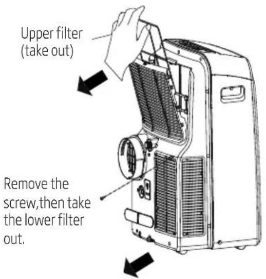
Remove the air filter

Warning:
Do not operate the unit without filter because dirt and lint will clog it and reduce performance.
6 Maintenance
Maintenance tips
- Be sure to clean the air filter every 2 weeks for optimal performance.
- The water collection tray should be drained immediately after P1 error occurs, and before storage to prevent mold.
- In households with animals, you will have to periodically wipe down the grill to prevent blocked airflow due to animal hair.
Clean the unit
Clean the unit using a damp, lint-free cloth and mild detergent. Dry the unit with a dry, lint-free cloth.
Store the unit when not in use
- Drain the unit's water collection tray according to the instructions in the following section.
- Run the appliance on Fan mode for 12 hours in a warm room to dry it and prevent mold.
- Turn off the appliance and unplug it.
- Clean the air filter according to the instructions in the previous section. Reinstall the clean, dry filter before storing.
- Remove the batteries from the remote control.
Be sure to store the unit in a cool, dark place. Exposure to direct sunshine or extreme heat can shorten the lifespan of the unit.

Note: The cabinet and front may be dusted with an oil-free cloth or washed with a cloth dampened in a solution of warm water and mild liquid dishwashing detergent. Rinse thoroughly and wipe dry. Never use harsh cleansers, wax or polish on the cabinet front. Be sure to wring excess water from the cloth before wiping around the controls. Excess water in or around the controls may cause damage to the unit.
7 Faults diagnosis
Please check the machine according to the following form before asking for maintenance:
| Problem Possible cause Troubleshooting | ||
| Unit does not turn on when pressing On/Off button | P1 Error code | The water collection tray is full. Turn off the unit, drain the water from the water collection tray and restart the unit. |
| In cool mode: room temperature is lower than the set temperature | Reset the temperature | |
| Unit does not cool well | The air filter is blocked with dust or animal hair | Turn off the unit and clean the filter according to instructions |
| Exhaust hose is not connected or is blocked | Turn off the unit, disconnect the hose, check for blockage and reconnect the hose | |
| The unit is low on refrigerant | Call a service technician to inspect the unit and top off refrigerant | |
| Temperature setting is too high | Decrease the set temperature | |
| The windows and doors in the room are open | Make sure all windows and doors are closed | |
| The room area is too large Double-check the cooling area | - check the cooling area | |
| There are heat sources inside the room | Remove the heat sources if possible | |
| The unit is noisy and vibrates too much | The ground is not level | Place the unit on a flat, level surface |
| The air filter is blocked with dust or animal hair | Turn off the unit and clean the filter according to instructions | |
| The unit makes a gurgling sound | This sound is caused by the flow of refrigerant in-side the unit | This is normal |
8 Design and compliance notes
Design notice
The design and specifications are subject to change without prior notice for product improvement. Consult with the sales agency or manufacturer for details. Any updates to the manual will be uploaded to the service website, please check for the latest version.
Energy rating information
The Energy Rating for this unit is based on an installation using an un-extended exhaust duct without window slider adaptor or wall exhaust adaptor A (as shown in the Installation section of this manual).
Unit temperature range
| Mode Temperature range | |
| Cool 17-35°C | |
| Dry 13-35°C | |
| Heat (pump heat mode) 5-30°C | |
| Heat (electrical heat mode) ≤ 30°C |

Note: To be in compliance EN 61000-3-11, the product BA 312 H shall be connected only to a supply of the system impedance: | Zsys I = 0.348 ohms or less, the product BA 312 C shall be connected only to a supply of the system impedance: | Zsys I = 0.362 ohms or less. Before connect the product to public power network, please consult your local power supply authority to ensure the power network meet above requirement.
9 Sociable remark
When using this unit in the European countries, the following information must be followed:
Disposal: Do not dispose this product as unsorted municipal waste. Collection of such waste separately for special treatment is necessary.
It is prohibited to dispose of this appliance in domestic household waste.
For disposal, there are several possibilities:
A) The municipality has established collection systems, where electronic waste can be disposed of at least free of charge to the user.
B) When buying a new product, the retailer will take back the old product at least free of charge.
C) The manufacture will take back the old appliance for disposal at least free of charge to the user.
D) As old products contain valuable resources, they can be sold to scrap metal dealers.
Wild disposal of waste in forests and landscapes endangers your health when hazardous substances leak into the ground-water and find their way into the food chain.
natural_image
Symbol of a trash bin crossed with a diagonal line, representing waste sorting or anti-smoking (no text present)
This symbol indicates that this product shall not be disposed with other household wastes at the end of its service life. Used device must be returned to official collection point for recycling of electrical and electronic devices. To find these collection systems please contact to your local authorities or retailer where the product was purchased. Each household performs important role in recovering and recycling of old appliance. Appropriate disposal of used appliance helps prevent potential negative consequences for the environment and human health.
10 Installation instructions
10.1 F-Gas instruction
This product contains fluorinated greenhouse gases covered by the Kyoto protocol.
The fluorinated greenhouse gases are contained in hermetically sealed equipment.
Installs, services, maintains, repairs, checks for leaks or decommissions equipment and product recycling should be carried out by natural persons that hold relevant certificates.
If the system has a leakage detection system installed, leakage checks should be performed at least every 12 months, make sure system operate properly.
If product must be performed leakage checks, it should specify Inspection cycle, establish and save records of leakage checks.

Note: For hermetically sealed equipment, portable air conditioner, window air conditioner and dehumidifier, if CO_2 equivalent of fluorinated greenhouse gases is less than 10 tonnes, it should not perform leakage checks.
11 Specification
| Beko model name BA 310 AC BA 312 H BA 312 C | ||||
| Refrigerant | R290 R290 R290 | |||
| Total refrigerant amount (g) | 200 230 | 210 | ||
| Climate class | T1 T1 T1 | |||
| Heating type | - Heat pump - | |||
| Cooling capacity (Btu/h) | 10000 12000 11680 | |||
| Cooling capacity (W) | 2931 3517 3423 | |||
| Heating capacity (Btu/h) | - 10000 - | |||
| Heating capacity (W) | - 2931 - | |||
| Energy efficiency cooling (W/W) | 3.1 2.71 | 2.61 | ||
| Energy efficiency heating (W/W) | - 2.91 - | |||
| Energy level-cooling | A+ A | A | ||
| Energy level-heating | - | A+ | - | |
| Cooling power input (W) | 945 | 1298 | 1314 | |
| Heating power input (W) | - 1007 - | |||
| Voltage/frequency (V/Hz) | 220V-240V 50Hz, 1Ph | 220V-240V 50Hz, 1Ph | 220V-240V 50Hz, 1Ph | |
| Packed unit (WxHxD) mm | 515x443x880 | 515x443x880 | 515x443x880 | |
| Unit weight - packed (kg) | 38 | 40 36.2 | ||
-
Specification are standard values calculate based on rated operation conditions. They will vary in difference work condition.
-
Our company has quick technical improvements. There will be no prior notice for any change of technical data. Please read nameplate on the air-conditioner.
-
Rated value is tested under 35/24(In.)35/24(Out).
Manufactured by Arcelik A.S. Karaagac Cd. No:2-6 34445 Sutluce, Beyoglu, Istanbul, Turkey.
Attention! Surfaces chaudes!
Ne pas couvrir.

Touche SWING (Oscillation)
natural_image
Line drawing of a portable air conditioner unit with cooling fins and ventilation slots (no text or symbols)6 Entretien
Avertissement :
natural_image
Symbol of a trash bin crossed with two diagonal lines, representing no waste or discharge (no text or labels)
natural_image
Three hand-drawn illustrations of coiled pipes with shaded surfaces, no text or symbols present5 Betrieb

natural_image
Line drawing of a portable air conditioner unit with cooling fins and buttons (no text or symbols)natural_image
Symbol of a trash bin crossed with diagonal lines, no text or numbers presentnatural_image
Line drawing of a vacuum cleaner emitting a hose, mounted on a device (no text or symbols)0
natural_image
Line drawing of a device with a coiled cable inserted into a window (no text or symbols)natural_image
Three hand-drawn illustrations of coiled or twisted pipe fittings, no text or symbols present5 Funzionamento

natural_image
Line drawing of a portable air conditioner unit with cooling fan and buttons (no text or symbols)6 Manutenzione
Avvertenza:
natural_image
Symbol of a trash bin with crossed lines indicating no waste or discharge, and a black rectangular block below (no text or labels)natural_image
Hand-drawn sketch of a coiled tube or pipe with a circular loop around it (no text or symbols)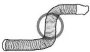
natural_image
Diagram of a curved pipe or tube with internal hatching, no text or symbols present5 Functionare

natural_image
Line drawing of a portable air conditioner unit with cooling fins and ventilation slots (no text or symbols)6 Intretinere
Atentionare:
natural_image
Symbol of a trash bin crossed with no visible text or labelsnatural_image
Abstract geometric design with blue triangular shapes on white background (no text or symbols)Air conditioner remote control
User Manual
EN FR DE|IT RO
02M-8500063200-4920-01
Please read this user manual first!
Dear Customer,
Thank you for preferring a Beko product. We hope that you get the best results from your product which has been manufactured with high quality and state-of-the-art technology. Therefore, please read this entire user manual and all other accompanying documents carefully before using the product and keep it as a reference for future use. If you handover the product to someone else, give the user manual as well. Follow all warnings and information in the user manual.
Meanings of the symbols
Following symbols are used in the various section of this manual:

Important information or useful hints about usage.

Warning for hazardous situations with regard to life and property.

Warning to actions that must never perform.
Warning for electric shock.
Warning for hot surfaces.
Do not cover it.

This symbol shows that the operation manual should be read carefully.
This symbol shows that a service personnel should be handling this equipment with reference to the installation manual.
This symbol shows that this appliance used a flammable refrigerant. If the refrigerant is leaked and exposed to an external ignition source, there is a risk of fire.

This product has been produced in environmentally friendly, modern facilities
CONTENTS
1 Remote control specifications 4
2 Function buttons 5
3 Handling the remote control 7
3.1 Inserting and replacing batteries ....7
4 Remote LED screen indicators 9
5 How to use the basic functions 10
5.1 Auto operation.... 10
5.2 Cool operation 11
5.3 Dry operation (dehumidifying).... 12
5.4 Fan operation....13
5.5 Heat operation....14
5.6 Setting the timer function 15
6 How to use the advanced functions 20
1 Remote control specifications
| Model | RG57H2(B)/BG(C)EF |
| Rated voltage | 3.0V (Dry batteries R03/LR03×2) |
| Signal receiving range | 8m |
| Environment | -5°C~60°C |
RG57H2(B)/BG(C)EF
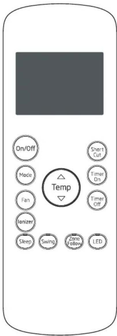
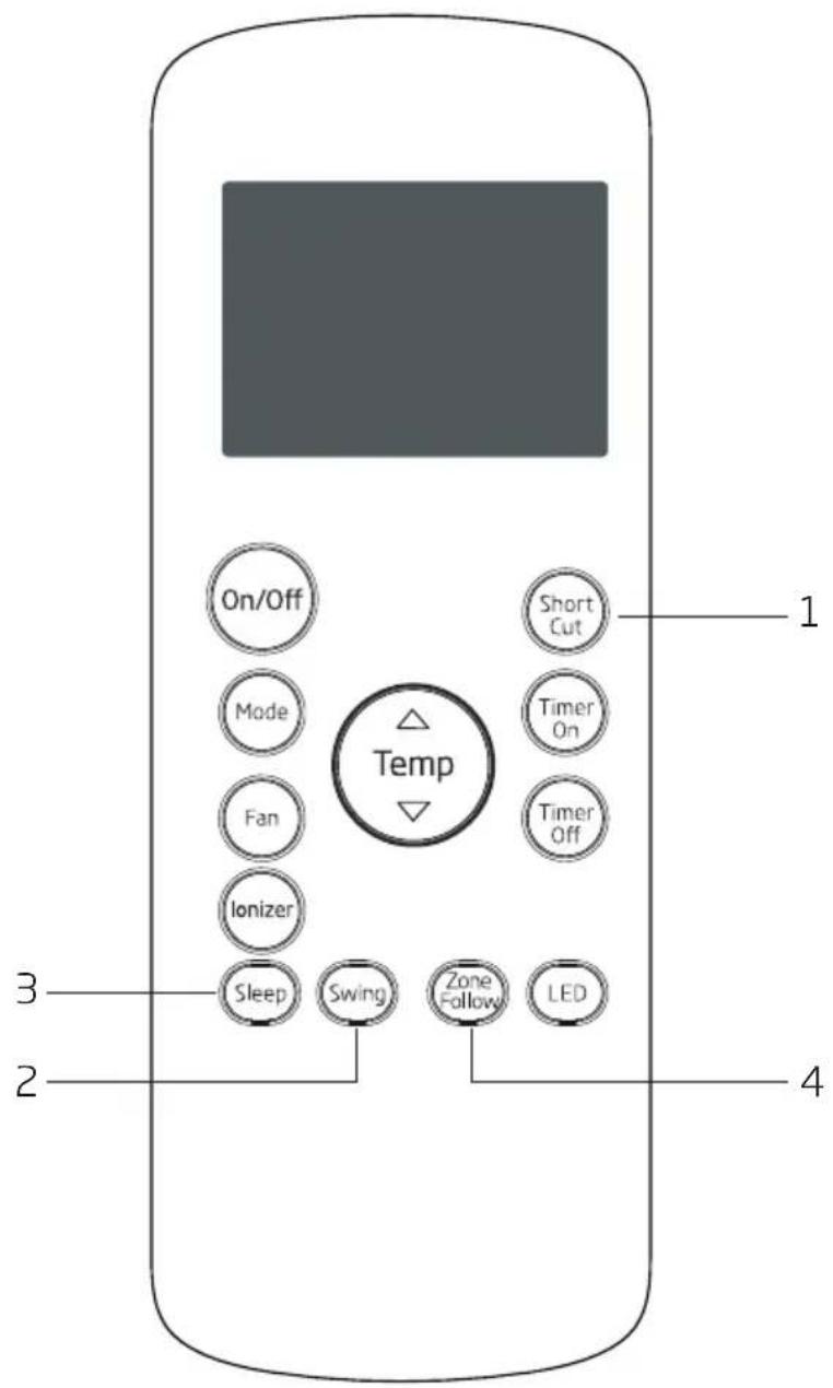
2 Function buttons
Before you begin using your new air conditioner, make sure to familiarize yourself with its remote control. The following is a brief introduction to the remote control itself. For instructions on how to operate your air conditioner, refer to the How to use the basic functions section of this manual.
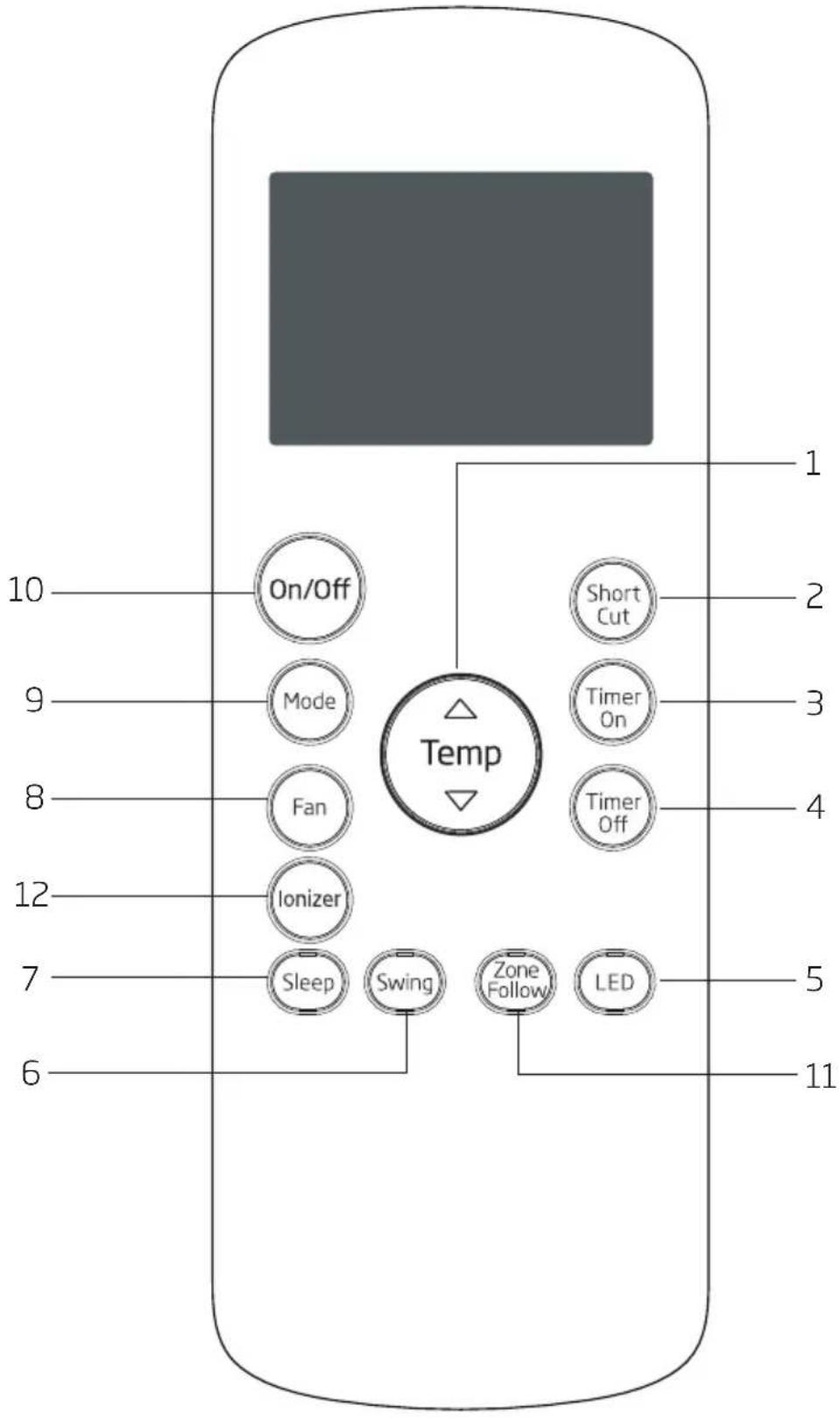
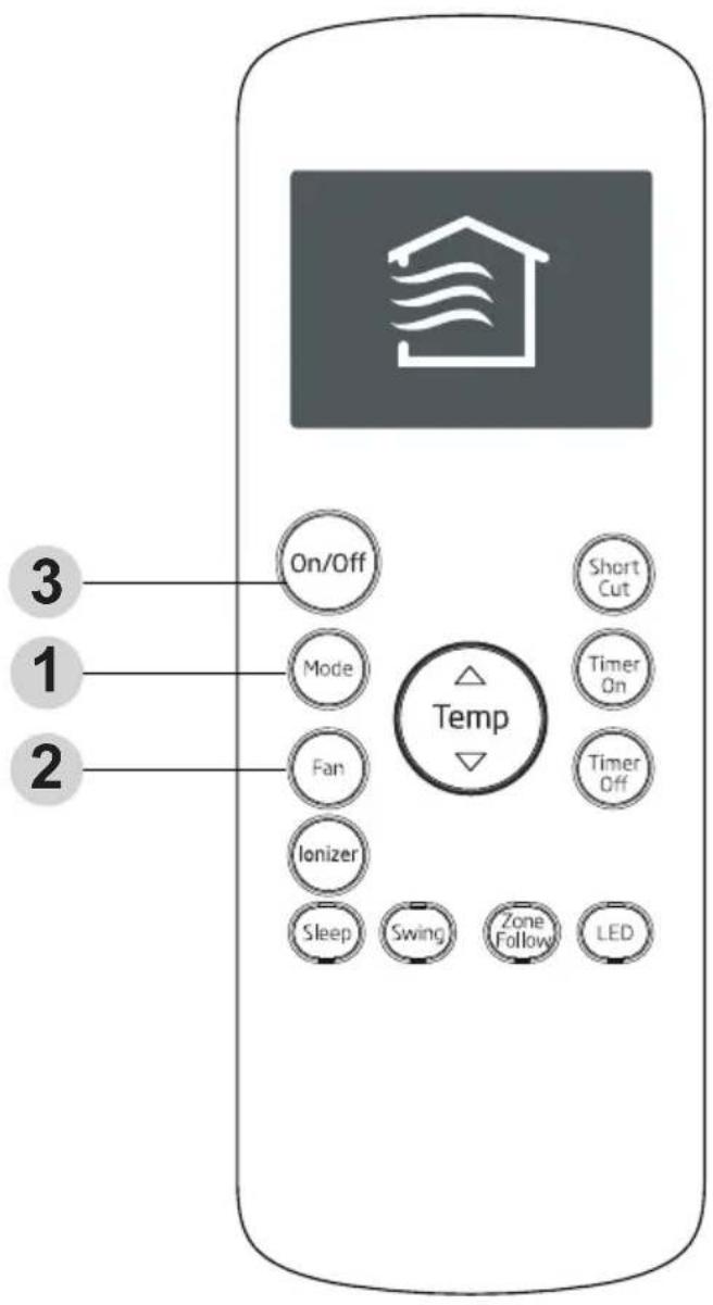
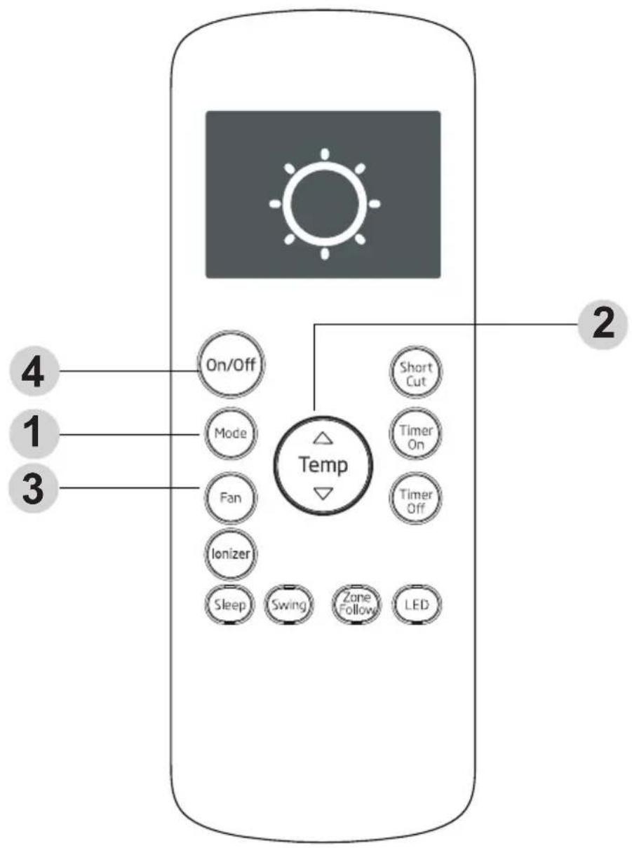
2 Function buttons
1. Temp
Increases temperate in 1°C increments. Max. temperature is 30°C.
Temp
Decreases temperate in 1°C increments. Min. temperature is 17°C.
2. Short Cut
Sets and activates your favorite pre-settings.
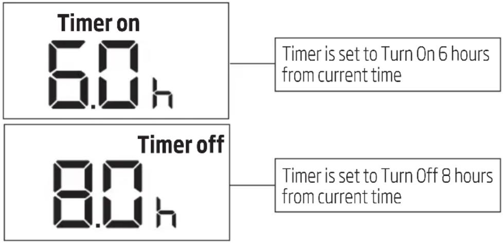
3. Timer On
Sets timer to turn unit on (see How to use the basic functions for instructions)
4. Timer Off
Sets timer to turn unit off (see How to use the basic functions for instructions)
5. LED
Turns indoor unit s LED display on and off. If you are sensitive to light when you go to sleep, you can press the LED button to turn off the LED display on the unit. Press the button again to turn it back on.
6. Swing
Starts and stops louver movement.
7. Sleep
Saves energy during sleeping hours.
8. Fan speed
Selects fan speeds in the following order: Auto-Low Med → High
9. Mode
Scrolls through operation modes as follows: Auto Cool Dry Heat Fan→

Note: Please do not select Heat mode if the machine you purchased is cooling only type. Heat mode is not supported by the cooling only appliance.
10. On/Off
Turns the unit on or off.

Note: Swing feature is optional. RG57H1(B)/BG(C)E-M without med fan speed.
11. Zone Follow
Temperature sensing and room temperature display button.
12. Ionizer
Press this button, the lonizer is energized and will help to remove pollen and impurities from the air.
3 Handling the remote control
Not sure what a function does?
Refer to the How to use the basic functions and How to use the advanced functions sections of this manual for a detailed description of how to use your air conditioner.

Special note
- Button designs on your unit may differ slightly from the example shown.
- If the unit does not have a particular function, pressing that function's button on the remote control will have no effect.
- When there are wide differences between Remote control Illustration and USER'S MANUAL on function description, the description of "USER'S MANUAL" shall prevail.
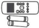
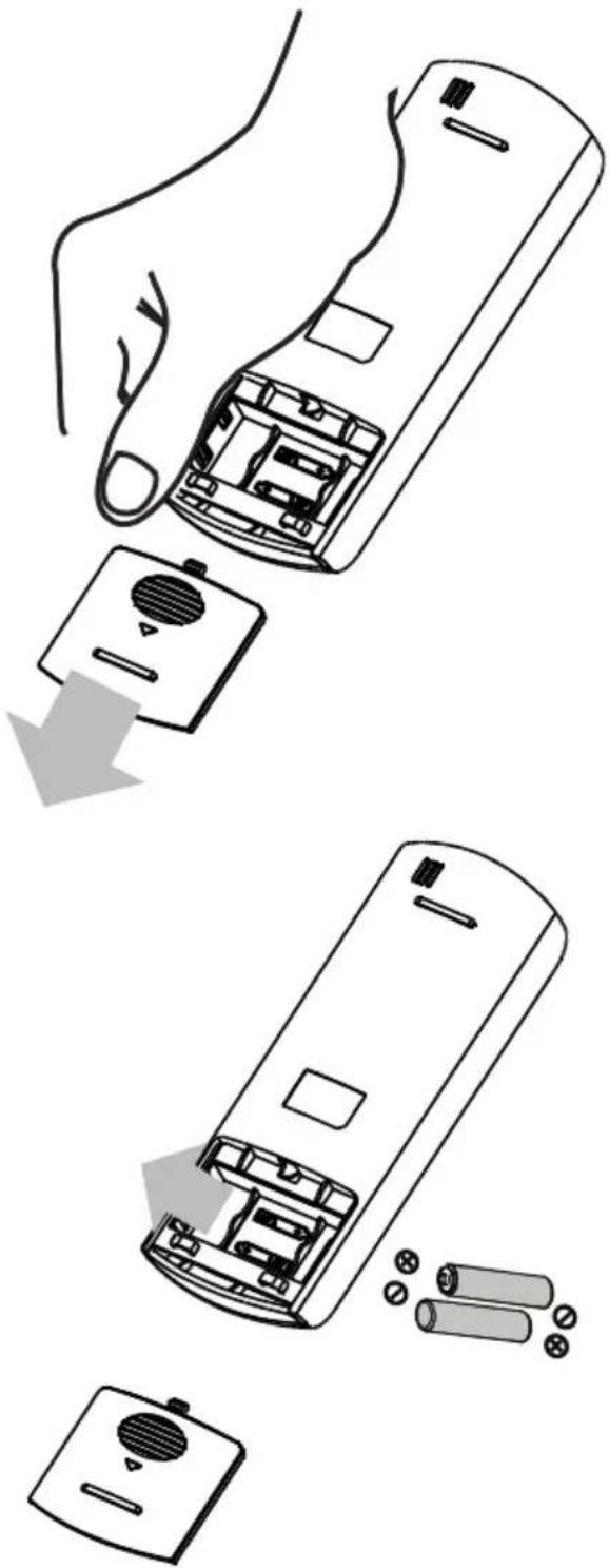
3.1 Inserting and replacing batteries
Your air conditioning unit comes with two AAA batteries. Put the batteries in the remote control before use.
- Slide the back cover from the remote Control downward, exposing the battery compartment.
- Insert the batteries, paying attention to match up the (+) and (-) ends of the batteries with the symbols inside the battery compartment.
- Slide the battery cover back into place.

Battery notes
For optimum product performance:
- Do not mix old and new batteries, or batteries of different types.
- Do not leave batteries in the remote control if you don't plan on using the device for more than 2 months.

Battery disposal
Do not dispose of batteries as unsorted municipal waste. Refer to local laws for proper disposal of batteries.
Tips for using remote control
- The remote control must be used within 8 meters of the unit.
- The unit will beep when remote signal is received.
- Curtains, other materials and direct sunlight can interfere with the infrared signal receiver.
- Remove batteries if the remote will not be used more than 2 months.
3 Handling the remote control
natural_image
Illustration of a hand holding a remote control with battery and battery pack components, showing internal circuitry and battery arrangement (no text or symbols)4 Remote LED screen indicators
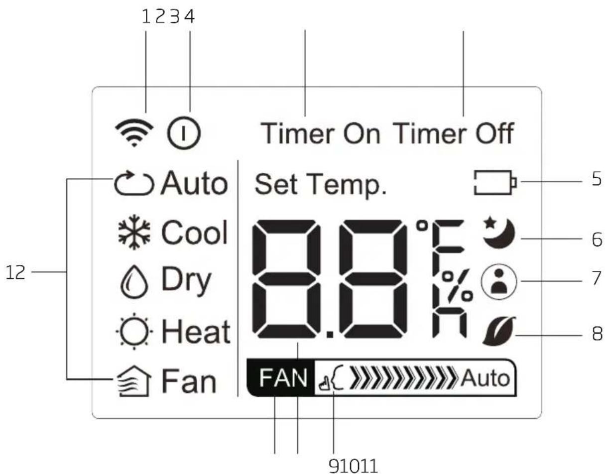
- Transmission indicator
Lights up when remote sends signal to unit
- On/Off display
Appears when the unit is turned on, and disappears when it is turned off
- Timer On display
Displays when Timer On is set
- Timer Off display
Displays when Timer Off is set
- Battery display
Low battery detection
- Sleep display
Displays when Sleep function is activated
- Zone Follow display
Indicates that the Zone Follow function is on
-
Not available for this unit
-
Silent display
Not available for this unit
- Temperature/Timer display
Displays the set temperature by default, or timer setting
when using Timer On/Off functions
• Temperature range: 17-30°C
- Timer setting range: 0-24 hours
This display is blank when operating in Fan mode.
- Fan speed display
Displays selected Fan Speed: >>>>>> High, >>>>>> Med, or >>ow
This display is blank when set to Auto speed.
- Mode display
Displays the current mode, including:
- Auto
• Cool
• Dry
- Heat
- Fan
5 How to use the basic functions
Setting temperature
The operating temperature range for units is 17-30°C. You can increase or decrease the set tmeperature in 1°C increments.
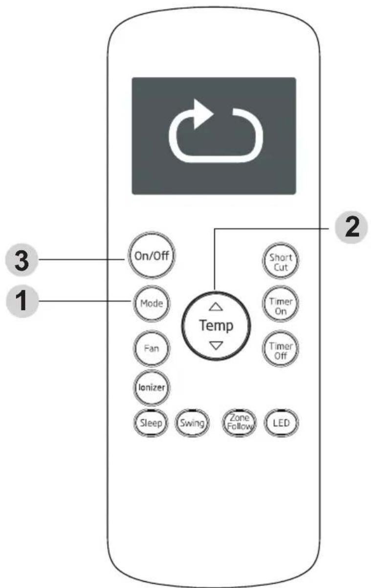
5.1 Auto operation
In Auto mode, the unit will automatically select the Cool, Fan, Heat or Dry mode based on the set temperature.
- Press the Mode button to select Auto mode.
- Set your desired temperature using the Temp or Temp button.
- Press the On/Off button to start the unit.

Note: Fan Speed can't be set in Auto mode.
5 How to use the basic functions
5.2 Cool operation
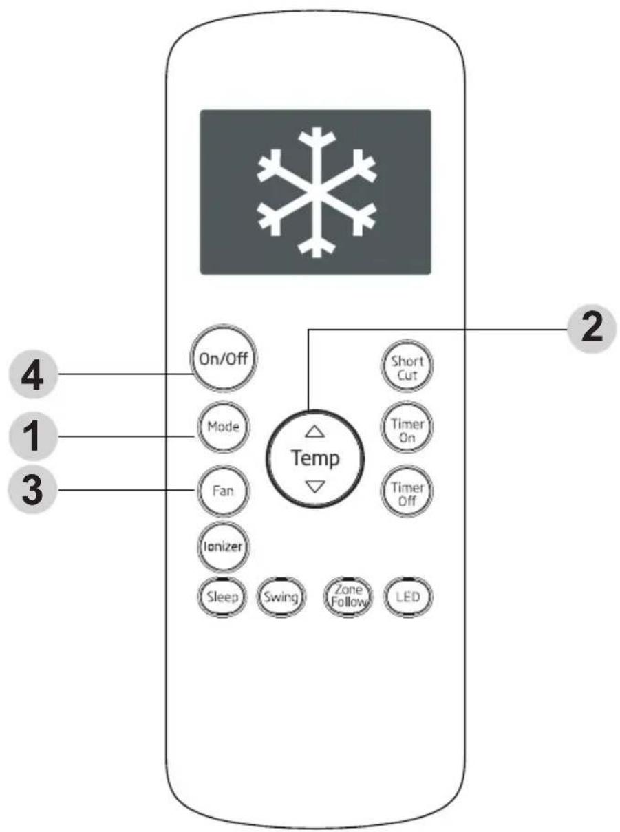
- Press the Mode button to select Cool mode.
- Set your desired temperature using the Temp or Temp button.
- Press the Fan button to select the Fan Speed: Auto, Low, Med, or High.
- Press the On/Off button to start the unit.
5 How to use the basic functions
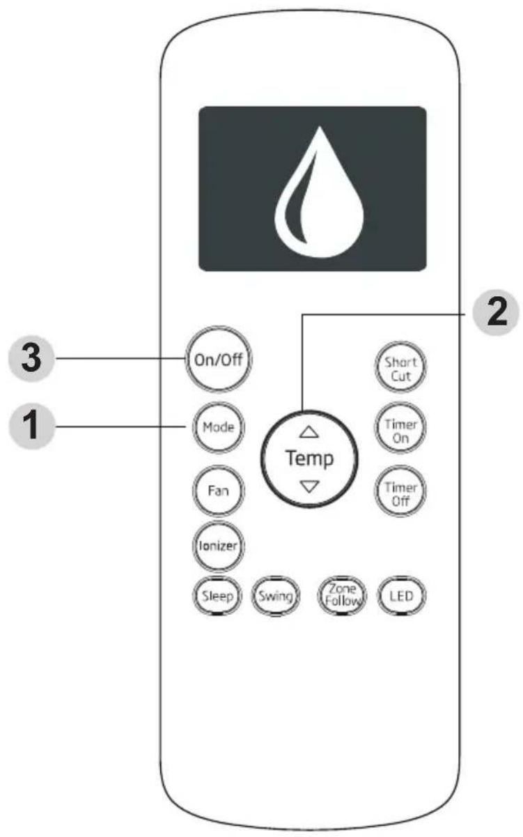
5.3 Dry operation (dehumidifying)
- Press the Mode button to select Dry mode.
- Set your desired temperature using the Temp or Temp button.
- Press the On/Off button to start the unit.

Note: Fan Speed can't be changed in Dry mode.
5 How to use the basic functions
5.4 Fan operation
- Press the Mode button to select Fan mode.
- Press Fan button to select the Fan Speed: Auto, Low, Med or High.
- Press the On/Off button to start the unit.

Note: You can t set temperature in Fan mode. As a result, your remote control's LCD screen will not display temperature.
5 How to use the basic functions
5.5 Heat operation
- Press the Mode button to select Heat mode.
- Set your desired temperature using the Temp or Temp button.
- Press the Fan button to select the Fan Speed: Auto, Low, Med, or High.
- Press the On/Off button to start the unit.

Note: As outdoor temperature drops, the performance of your unit s Heat function may be affected. In such instances, we recommend using this air conditioner in conjunction with other heating appliance.
5 How to use the basic functions
5.6 Setting the timer function
Your air conditioning unit has two timer-related functions:
Timer On- sets the amount of timer after which the unit will automatically turn on.
Timer Off- sets the amount of time after which the unit will automatically turn off.
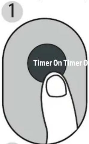
Timer On function
The Timer On function allows you to set a period of time after which the unit will automatically turn on, such as when you come home from work.
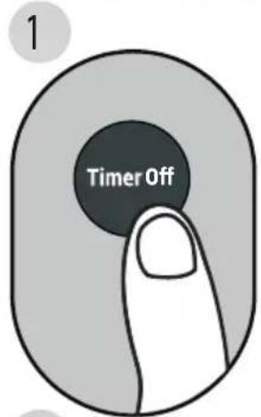
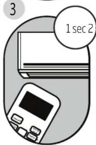
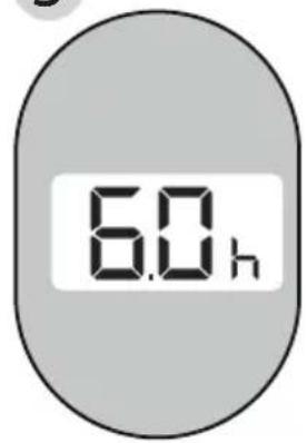
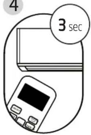
- Press the Timer On button. By default, the last time period that you set and an "h" (indicating hours) will appear on the display.

Note: This number indicates the amount of time after the current time that you want the unit to turn on.
For example, if you set Timer On for 2 hours, "2.0 h" will appear on the screen, and the unit will turn on after 2 hours.
- Press the Timer On button repeatedly to set the time when you want the unit to turn on.
- Wait 2 seconds, then the Timer On function will be activated. The digital display on your remote control will then return to the temperature display.
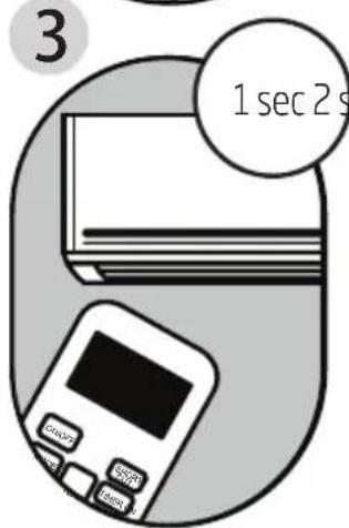
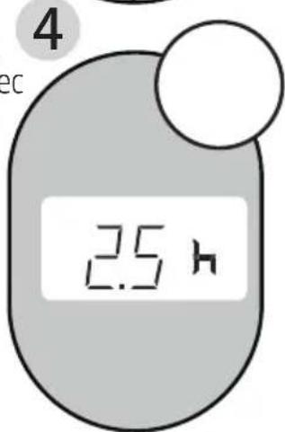
Example: Setting unit to turn on after 2.5 hours.
5 How to use the basic functions
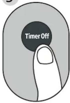
Timer Off function
The Timer Off function allows you to set a period of time after which the unit will automatically turn off, such as when you wake up.
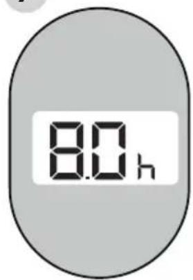
- Press the Timer Off button. By default, the last time period that you set and an "h" (indicating hours) will appear on the display.

Note: This number indicates the amount of time after the current time that you want the unit to turn off.
For example, if you set Timer Off for 2 hours, "2.0 h" will appear on the screen, and the unit will turn off after 2 hours.
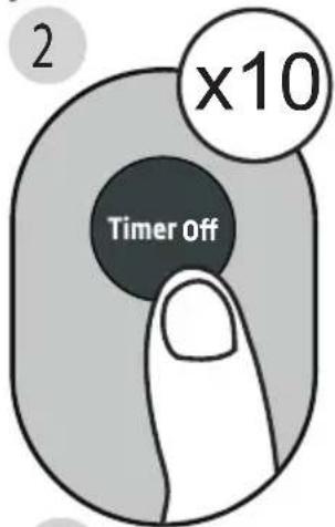
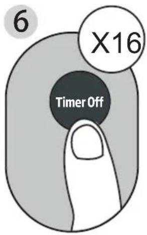
- Press the Timer Off button repeatedly to set the time when you want the unit to turn off.
- Wait 2 seconds, then the Timer Off function will be activated. The digital display on your remote control will then return to the temperature display.
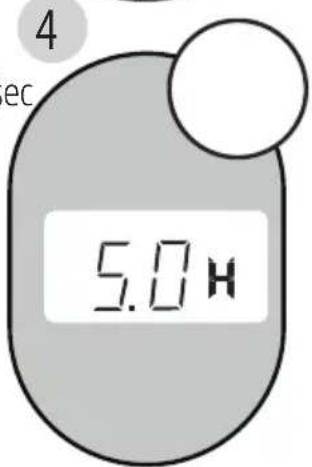
Example: Sectiong unit to turn off after 5

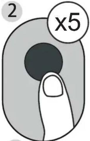
Note: When setting the Timer On or Timer Off functions, up to 10 hours, the time will increase in 30 minute increments with each press. After 10 hours and up to 24, it will increase in 1 hour increments. The timer will revert to zero after 24 You can turn off either function by setting its timer to "0.0h".
5 How to use the basic functions

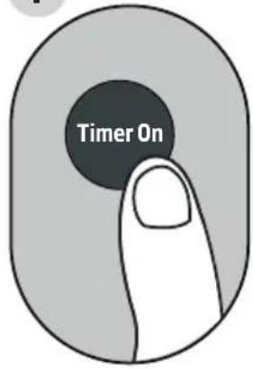
Continue to press
Timer On or Timer
Off until desired time
is reached.
5 How to use the basic functions
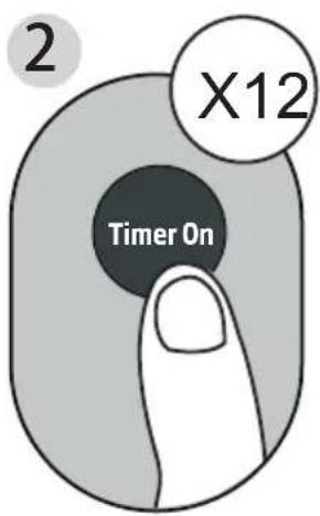
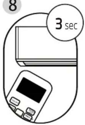
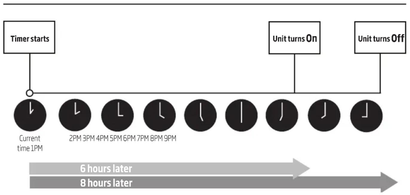
Setting both Timer On and Timer Off at the same time
Keep in mind that the time periods you set for both functions refer to hours after the current time. For example, say that the current time is 1:00 PM, and you want the unit to turn on automatically at 7:00 PM. You want it to operate for 2 hours, then automatically turn off at 9:00 PM.
Do the following:
1
3
4
5
7
8
5 How to use the basic functions
Example: Setting the unit to turn on after 6 hours, operate for 2 hours, then turn off (see the figure below)
Your remote display
flowchart
graph LR
    A["Timer starts"] --> B["Current time 1PM"]
    B --> C["2PM 3PM 4PM 5PM 6PM 7PM 8PM 9PM"]
    C --> D["Unit turns On"]
    D --> E["Unit turns Off"]
    style A fill:#f9f,stroke:#333
    style B fill:#ccf,stroke:#333
    style C fill:#cfc,stroke:#333
    style D fill:#fcc,stroke:#333
    style E fill:#cff,stroke:#333
    note right of B: 6 hours later
    note right of E: 8 hours later
6 How to use the advanced functions
1. Short cut function
• Used to restore the current settings or resume previous settings.
- Push this button when remote controller is on, the system will automatically revert back to the previous settings including operating mode, setting temperature, fan speed level and sleep feature (if activated).
- If pushing more than 2 seconds, the system will automatically restore the current operation settings including operating mode, setting temperature, fan speed level and sleep feature (if activated).
2. Swing function
Used to stop or start louver movement and set the desired up/down air flow direction. The louver changes 6 degrees in angle for each press (some models without). If keep pushing more than 2 seconds, the louver auto swing feature is activated.
6 How to use the advanced functions
3. Sleep function
The Sleep function is used to decrease energy use while you sleep (and don't need the same temperature settings to stay comfortable). This function can only be activated via remote control.

Note: The sleep function is not available in Fan or Dry mode.
4. Zone Follow function
The Zone Follow function enables the remote control to measure the temperature at its current location. When using Auto, Cool, or Heat functions, measuring ambient temperature from the remote control (instead of from the indoor unit itself) will enable the air conditioner to optimize the temperature around you and ensure maximum comfort.
- Press Zone Follow button to activate function. The remote control will send temperature signal to the indoor unit every three minutes.
- Press Zone Follow button again to turn off this function.
 | Note:- Buttons design is based on typical model and might be slightly different from the actual one you purchased, the actual shape shall prevail.- All the functions described are accomplished by the unit, if the unit has no this feature, there is no corresponding operation happened when press the relative button on the remote controller.- When there are wide differences between Remote controller Illustration and USERS MANUAL on function description, the description on USERS MANUAL shall prevail.- This equipment has been tested and found to comply with the limits for a Class B digital device, pursuant to part 15 of the FCC Rules. These limits are designed to provide reasonable protection against harmful interference in a residential installation. This equipment generates, uses and can radiate radio frequency energy and, if not installed and used in accordance with the instructions, may cause harmful interference to radio communications. However, there is no guarantee that interference will not occur in a particular installation. If this equipment does cause harmful interference to radio or television reception, which can be determined by turning the equipment off and on, the user is encouraged to try to correct the interference by one or more of the following measures:Reorient or relocate the receiving antenna.Increase the separation between the equipment and receiver.Connect the equipment into an outlet on a circuit different from that to which the receiver is connected.Consult the dealer or an experienced radio/TV technician for help. Changes or modifications not approved by the party responsible for compliance could void suers authority to operate the equipment. |
Attention! Surfaces chaudes!
Ne pas couvrir.
RG57H2(B)/BG(C)EF
natural_image
Illustration of a hand holding a remote control with battery and battery pack components, showing internal circuitry and battery arrangement (no text or symbols)• le mode Heat (Chauffage)
2. Mode Swing (oscillation)
RG57H2(B)/BG(C)EF
2 Funktionstasten
natural_image
Illustration of a hand holding a remote control with battery and battery pack components, showing internal circuitry and battery arrangement (no text or symbols)RG57H2(B)/BG(C)EF
2 Tasti funzione
natural_image
Illustration of a hand holding a remote control with battery and battery pack components, showing internal circuitry and battery arrangement (no text or symbols)RG57H2(B)/BG(C)EF