
VXT7-B2 - Wall mount SANUS - Free user manual and instructions
Find the device manual for free VXT7-B2 SANUS in PDF.

User questions about VXT7-B2 SANUS
0 question about this device. Answer the ones you know or ask your own.
Ask a new question about this device
Download the instructions for your Wall mount in PDF format for free! Find your manual VXT7-B2 - SANUS and take your electronic device back in hand. On this page are published all the documents necessary for the use of your device. VXT7-B2 by SANUS.
USER MANUAL VXT7-B2 SANUS
natural_image
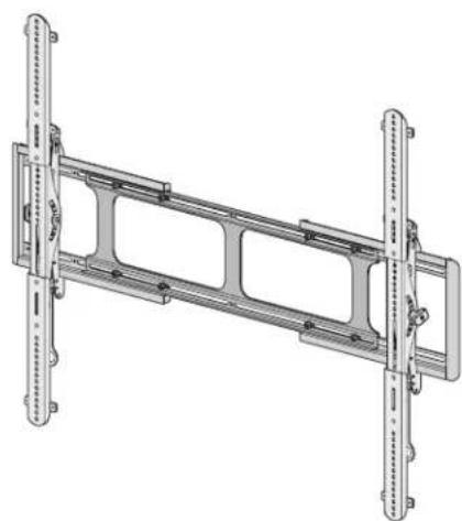
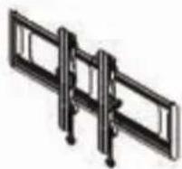
Technical line drawing of a mechanical frame assembly with vertical supports and mounting holes (no text or symbols)VXT7-B2
INSTRUCTION MANUAL
GET IT RIGHT
THE FIRST TIME
Follow this step-by-step instruction manual to speed up your installation.
WE'RE HERE TO HELP
Want to watch a video that shows how easy this DIY project will be?
Watch it now at: SANUS.com/2817
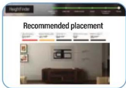
Get it right the first time. HeightFinder™ shows you where to drill.

Check it out at: SANUS.com/2567

natural_image
Group of employees in an office setting, one wearing a headset, seated at desks (no visible text or symbols)Our install experts are standing by to help.
Call us at: US:+1(800)359-5520 EMEA:+31(0)495 580 852 UK:+44(0)800 056 2853
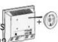
Before you begin
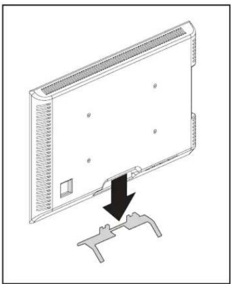
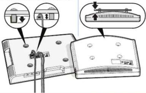
Remove the stand from your TV — if attached.
Install any accessories
you may have purchased — if they require the TV to be removed from the wall for assembly. The TV is removable for future accessory purchases.
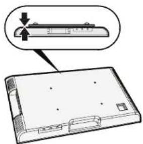
Protect the face of your TV when laying it down for installation.
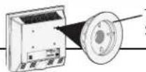
natural_image
Diagram of a flat-screen TV rear panel with a black arrow pointing to a connector bracket (no text or symbols present)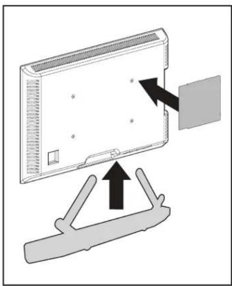
natural_image
Diagram showing a device with an arrow pointing to a component, mounted on a stand (no text or symbols present)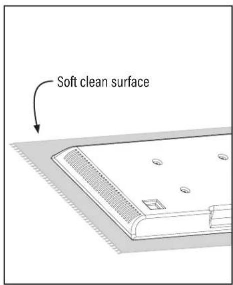
IMPORTANT SAFETY INSTRUCTIONS - PLEASE READ MANUAL PRIOR TO USE - SAVE THESE INSTRUCTIONS
Please read through these instructions completely to be sure you're comfortable with this easy install process.
Check your TV owner's manual to see if there are any special requirements for mounting your TV.
If you do not understand these instructions or have doubts about the safety of the installation, assembly or use of this product,
contact Customer Service: +1 (800) 359-5520 (EMEA: +31 (0) 495 580 852; UK: +44 (0) 800 056 2853)

CAUTION: Avoid potential personal injuries and property damage!
- This product is designed ONLY to be installed into wood studs, solid concrete or concrete block.
— DO NOT INSTALL INTO DRYWALL ALONE — DRYWALL ALONE WILL NOT HOLD THE WEIGHT OF YOUR TV.
● This product is designed for INDOOR USE ONLY. - The wall must be capable of supporting five times the weight of the TV and mount combined.
- Do not use this product for any purpose not explicitly specified by manufacturer.
● Manufacturer is not responsible for damage or injury caused by incorrect assembly or use.
TV Weight Limit
(including accessories)
DO NOT EXCEED
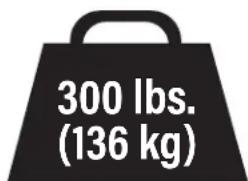
If your TV (including accessories) exceeds this weight, this mount is NOT compatible.
Visit SANUS.com or call customer service to find a compatible mount.
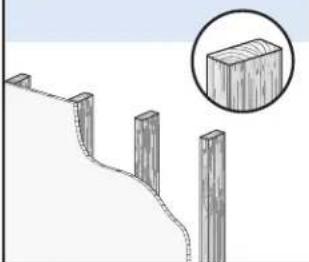
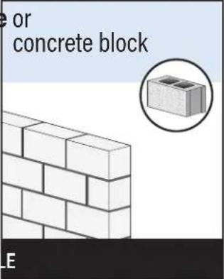
Wall Construction
ONLY install on these acceptable wall types.

Unsure
Call Customer Service

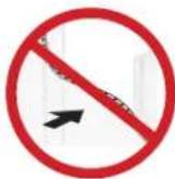
CAUTION:
DO NOT install in drywall alone
Drywall alone will NOT hold the weight of your TV.
wood studs Solid concrete
natural_image
Diagram of a wooden fence structure with a magnified inset showing a rectangular block (no text or symbols)ACCEPTABLE ACCEPT
Tools Needed
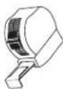
Measure
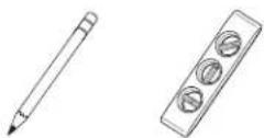
Pencil Level Tape

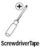
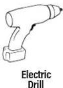
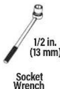
Wood Stud Install
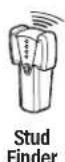
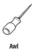

Drill Bit
Concrete Install
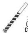
Drill Bit
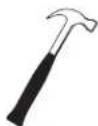
Hammer
Attach TV Bracket to TVSTEP 1

WARNING: This product contains small items that could be a choking hazard if swallowed. Before starting assembly, verify all parts are included and undamaged. If any parts are ng or damaged, do not return the damaged item to your dealer; contact Customer Service. Never use damaged parts!

NOTE: Not all hardware included will be used.
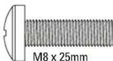
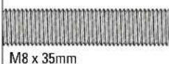
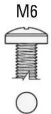
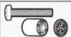
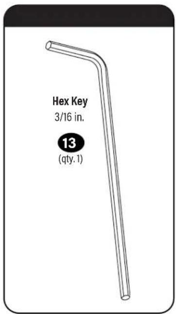
STEP 1 Parts and Hardware

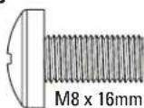
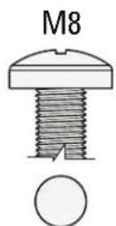
TV Screws (qty. 4 each)
[Only one size fits your TV]
M6
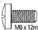
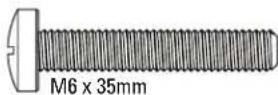
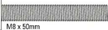
M8
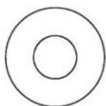
Washer
(qty, 4 each)

M6/M8
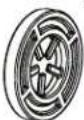
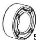
Spacers
[If necessary] (qty. 4 each)

M6/M8
2.5mm
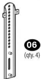
TV Brackets
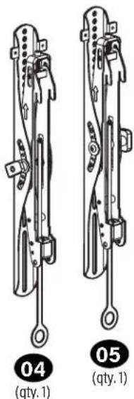
TV Bracket Extension

Washer


(qty. 8)

Nut

(qty, 8)
Only one screw size fits your TV.
If your TV included inset spacers or wall mount adapters see Troubleshooting on PAGE 22:
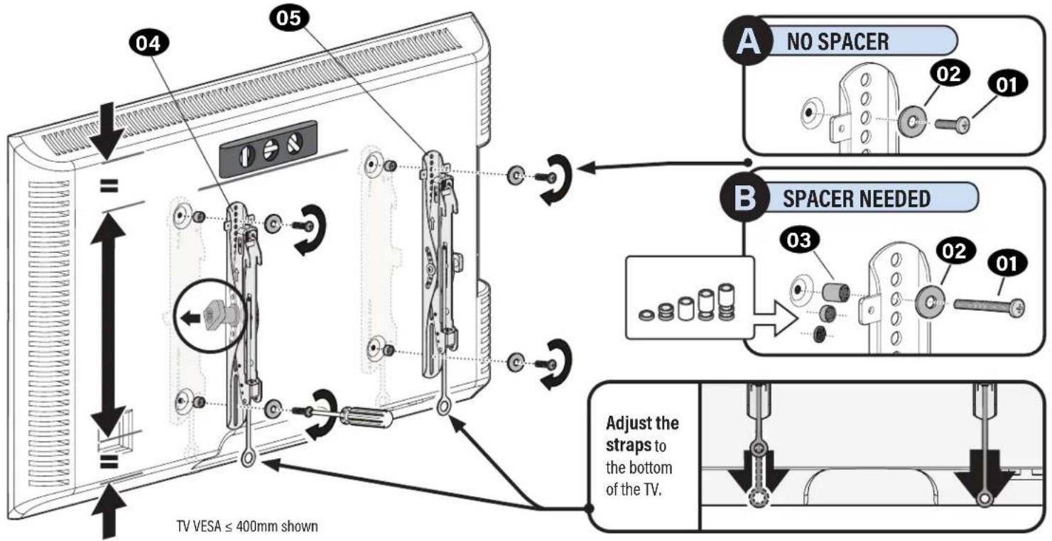
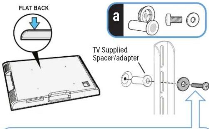
1.2 Select TV Screw Length and Spacers1.1 Select TV Screw Diameter

NO SPACER SPACER
- Flat Back TV
[TV brackets lay flat on your TV]
Use short TV screws 01 Spacers 03 not needed.

natural_image
Diagram of a device with a magnified view showing a small component (no text or symbols present)BD
- Flat Back TV with Extra Space Needed [for deep inset holes or cable interference]
- Rounded or Irregular Back TV [TV brackets NOT resting flat on your TV]
Use long TV screws 01 and spacers 03 to create extra space between the TV and TV bracket.
Inset Holes Cables Rounded Back
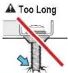
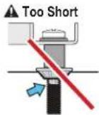
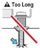
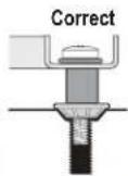
CAUTION: Verify adequate thread engagement with your screw 01, washer 02, spacer 03 combination AND TV bracket 04 / 05 / 06. — Too short will not hold your TV. — Too long will damage your TV.
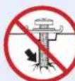
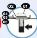
Too Short Too Long Correct
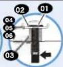
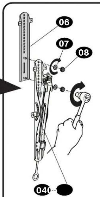
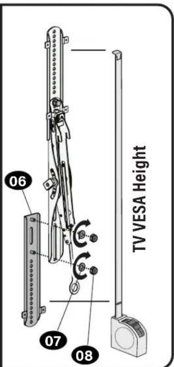
1.3 Determine Your TV Bracket Configuration
Measure the HEIGHT of your TV mounting hole pattern.
For Height 400mm or less
Skip to STEP 1.4 on PAGE 9
≤ 400mm (15 3/4 in.)
For height greater than 400mm
Assemble TV bracket extensions 06 to fit over your TV VESA height.
natural_image
Technical diagram of a device with labeled components and connection lines (no readable text or symbols)400mm (15 34 in.)
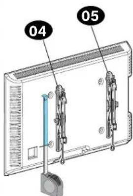
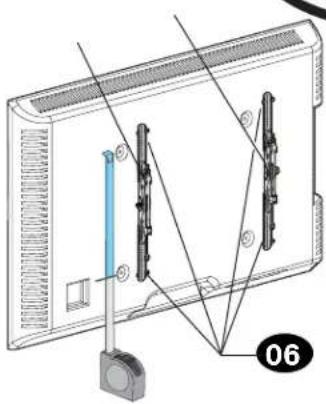
1.4 Attach TV Brackets to Your TV
Center the TV brackets 04 and 05 on your TV hole pattern, and install using your screw/washer/spacer.
STEP 2
Attach Wall Plate to Wall

WARNING:
This product contains small items that could be a choking hazard if swallowed. Before starting assembly, verify all parts are included and undamaged. If any
parts are missing or damaged, do not return the damaged item to your dealer; contact Customer Service.
Never use damaged parts!

NOTE:
Not all hardware included will be used.
Parts and Hardware for STEP 2 Tool for Adjustments
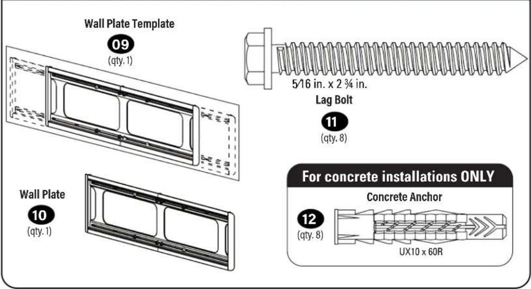
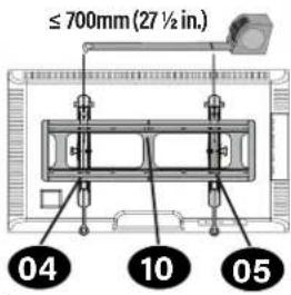
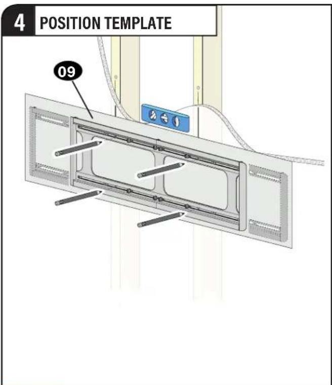
Determine Your Wall Plate Configuration
Measure the distance between your TV brackets 04 / 05.
For TV brackets 700mm or less \*
Skip to STEP: 2A (wood Stud) on PAGE 12 or 2B (concrete) on PAGE 15
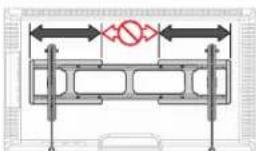
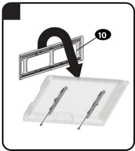
For TV brackets greater than 700mm
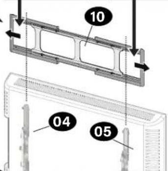
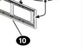
Extend the wall plate to fit the TV brackets.
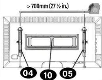
Extend your wall plate 10 beyond your TV brackets 04 / 05, but not past your TV edges.
WARNING: Avoid potential personal injuries! These areas could be pinch points when sliding back together.
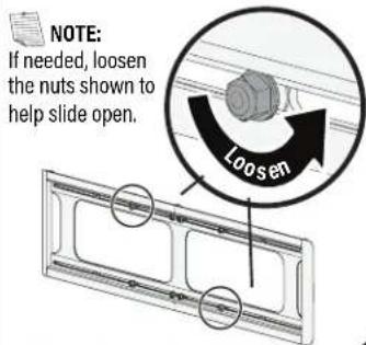
NOTE: For Wood Stud Installations ONLY: You can extend the wall plate to allow your TV to shift side-to-side. Be sure to not extend the wall plate past your TV edge.

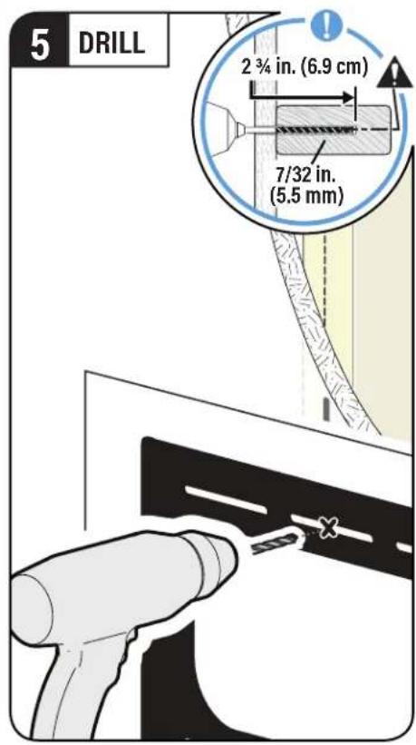
STEP 2A
Wood Stud Installation
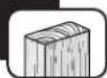
CAUTION: Avoid potential personal injury or property damage!
- Drywall covering the wall must not exceed 5/8 in. (1.5 cm)
● Minimum wood stud size: common 2 x 4 in. (5.1 x 10.2 cm) nominal 1½ x 3½ in. (3.8 x 8.9 cm)
● Minimum horizontal space between fasteners:16 in. (40.6 cm)
• Stud centers must be verified
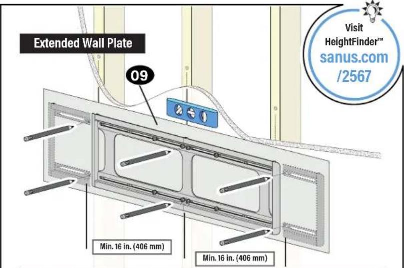

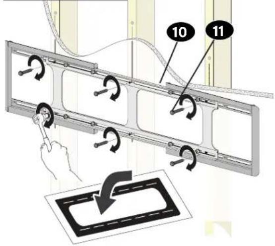
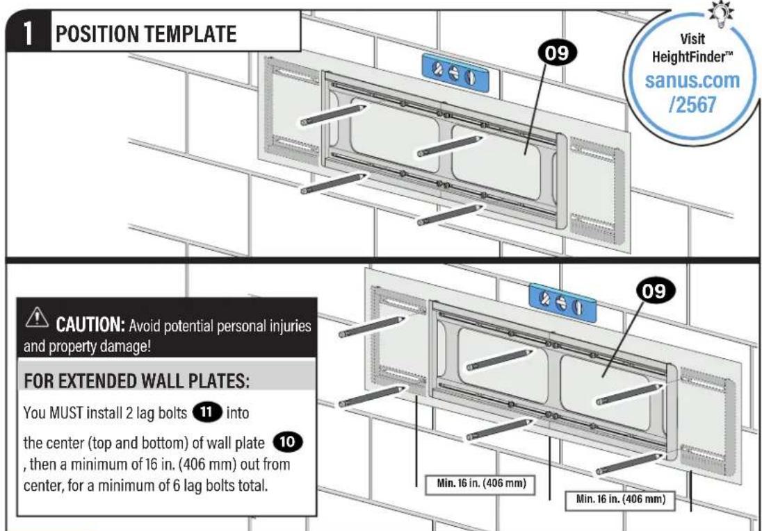
CAUTION: Avoid potential personal injuries and property damage!
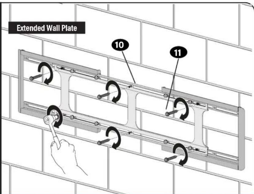
FOR EXTENDED WALL PLATES:
You MUST install 2 lag bolts 11 into the center (top and bottom)
of wall plate 10, then a minimum of 16 in. (406 mm) out from center, for a minimum of 6 lag bolts total.

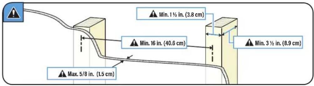
TIP:
To calculate your precise wall plate 10 location, check out our HeightFinder at sanus.com [www.sanus.com/2567].
STEP 2A
(continued)
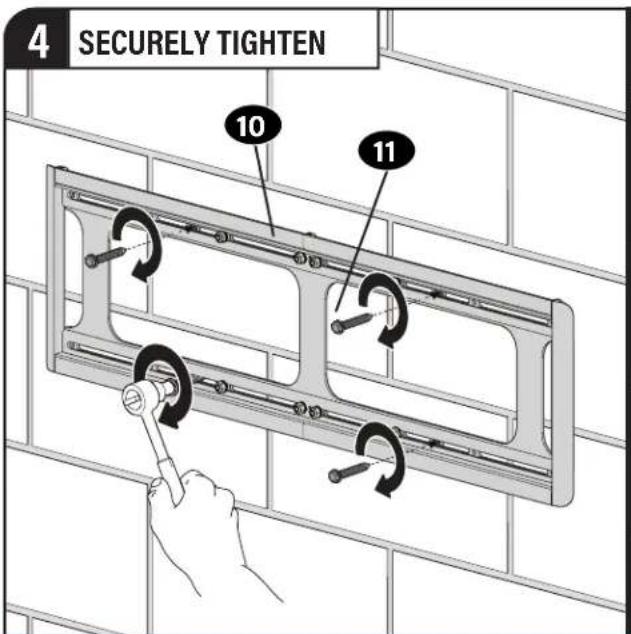
6 SECURELY TIGHTEN
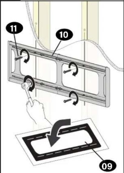
Extended Wall Plate
AUTION: Avoid potential personal injury or property damage!
All lag bolts 11 MUST BE firmly tightened to prevent unwanted movement of the wall plate 10. Ensure the wall plate is securely fastened to the wall before continuing on to the next step.
STEP 2B
Solid Concrete or Concrete Block Installation
AUTION:
Avoid potential personal injury or property damage!
- Mount the wall plate 10 directly onto the concrete surface (no surface covering)
● Minimum solid concrete thickness: 8 in. (20.3 cm)
● Minimum concrete block size: 8 x 8 x 16 in. (20.3 x 20.3 x 40.6 cm)
● Minimum horizontal space between fasteners: 16 in. (40.6 cm) - For concrete applications, TV brackets 04 and 05 must remain centered in wall plate 10. Keep this in mind when selecting the wall plate location

TIP:
To calculate your precise wall plate 10 location, check out our HeightFinder at sanus.com [www.sanus.com/2567].
STEP 2B
(continued)

UTION: Avoid potential personal injury or property damage!
All lag bolts 11 MUST BE firmly tightened to prevent unwanted movement of the wall plate 10. Ensure the wall plate is securely fastened to the wall before continuing on to the next step.
Go to STEP 3 on PAGE 19
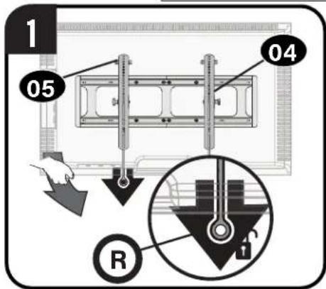
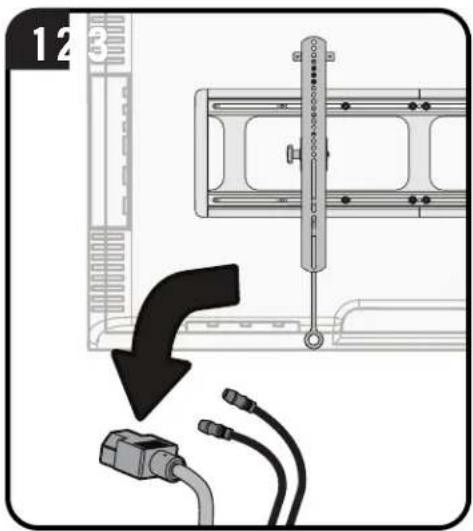
STEP 3
Attach TV to Wall Plate
1 HANG

HEAVY! You may need assistance with this step.
natural_image
Diagram of a mechanical device with directional arrows indicating movement (no text or symbols)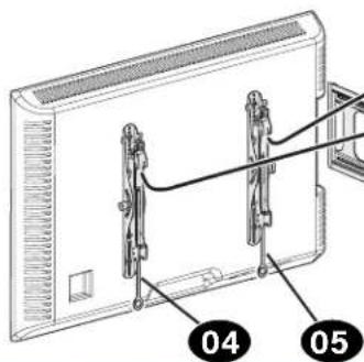
AUTION: Avoid potential personal injury or property damage!
For CONCRETE APPLICATIONS:
TV brackets 04 and 05 MUST remain centered in wall plate 10.
For extended wall plates:
TV brackets 04 and 05 must only hang on the OUTER sections of wall plate 10
natural_image
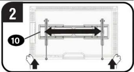
Pure mechanical component diagram without any text, numbers, or symbols2 ATTACH
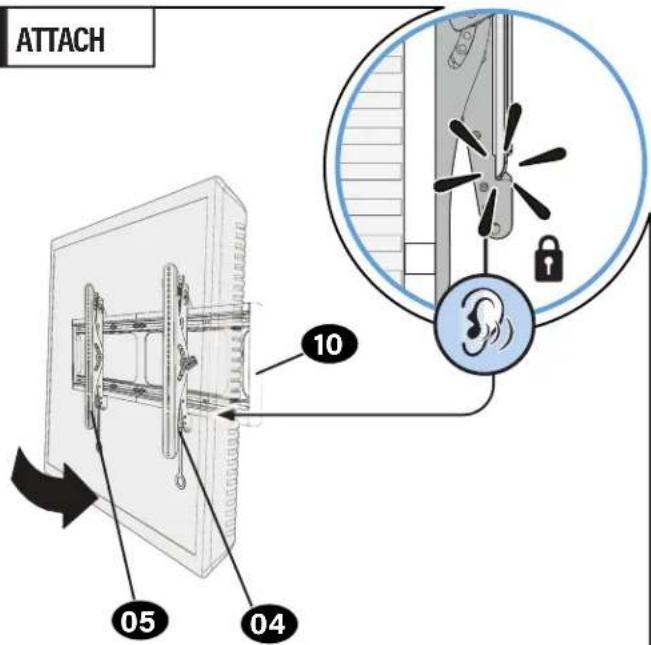
AUTION: Avoid potential personal injury or property damage!
Always make sure TV brackets 04 and 05 are in the locked position so the TV is securely fastened to the wall plate 10.
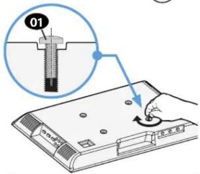
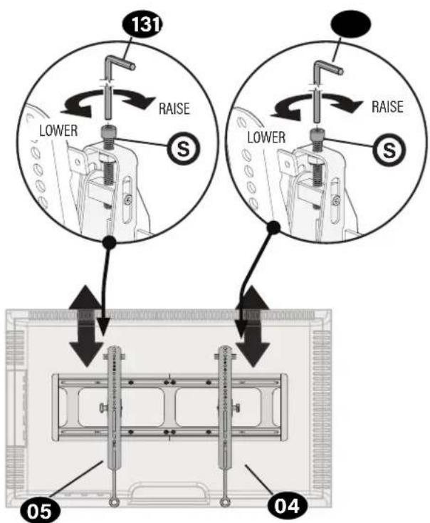
Adjustments
LEVELHEIGHT
To level your TV, turn the level adjustment screw
S on the top of either TV bracket 04 and 05 to
raise or lower that respective side of the TV.
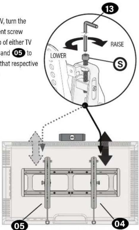
Adjust the height by turning the level adjustment screw S on the top of both TV brackets 04 and 05
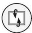
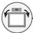
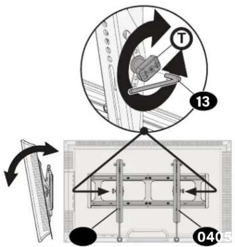
TILT TV LATERAL SHIFT
Your TV should adjust easily when moved, then stay in place.
Adjust the tilt tension knob T if your TV naturally tilts up or down.
NOTE: If you do not intend to adjust the tilt for different viewing locations, you can tighten the tilt tension knobs T to prevent unwanted movement.

CAUTION: Avoid potential personal injury or property damage! For
CONCRETE APPLICATIONS:
TV brackets 04 and 05 MUST remain centered in wall plate 10.
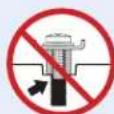
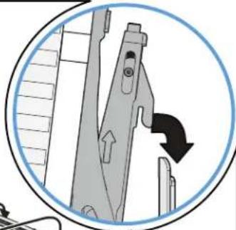
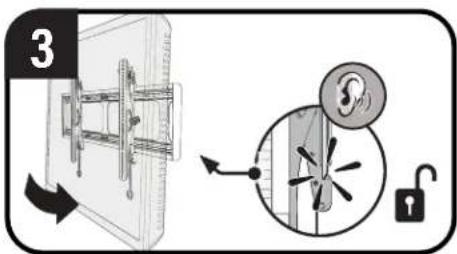
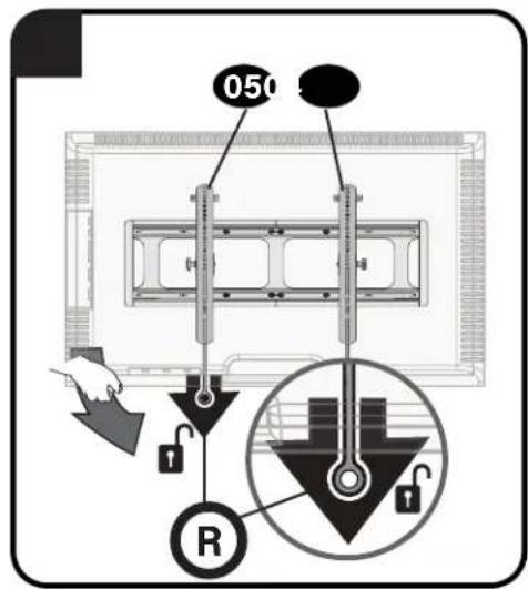
To unlock your TV: Pull down AND HOLD both release tabs ☑ while gently pulling the bottom of the TV away from the wall.
CAUTION: Avoid potential personal injury or property damage!
To prevent breaking the locking latch: always pull and hold release tabs R down while pulling the TV away from the wall.
Lift your TV up then carefully reposition on the wall plate. The wall plate 10 has stops to limit lateral movement.
Press the bottom of your TV into the wall plate 10 until you hear the lock click, securing the TV in place.
REMOVING THE TV
CAUTION: Avoid potential personal injury or property damage!
To prevent breaking the locking latch: always pull and hold release tabs R down while pulling the TV away from the wall.
NOTE: To rehang the TV, follow the procedures in STEP 3 on PAGE 18.

Troubleshooting
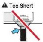
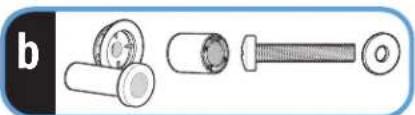
TV supplied spacers
TV Supplied Spacers
a: Use your TV supplied spacer/adapter for flat back TVs (AND you want your TV closer to the wall).
CAUTION: Avoid potential injury or property damage! Use the correct screw length for adequate thread engagement.
- Too short will not hold the TV.
- Too long will damage the TV.
If you are uncertain about your hardware selection, contact Customer Service.
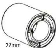
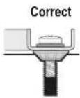
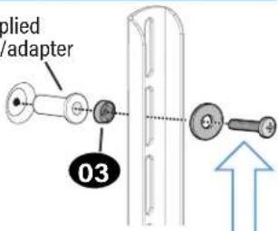
b: Use your TV supplied spacer/adapter and spacer 03 for:
- Round (irregular) back TVs
- Extra space needed for cables
ROUND BACK CABLES

natural_image
Illustration of three mechanical components: a cylindrical roller, a cylindrical bushing, and a flat bolt (no text or symbols)TV Supplied
Spacer/adapter
CAUTION: Avoid potential injury or property damage! Use the correct screw length for adequate thread engagement.
- Too short will not hold the TV.
- Too long will damage the TV.
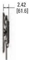
Dimensions
in. [mm]
TV INTERFACE
![43.31 [1100.0] 7.87 [200.0] 31.50 [800.0] 16.73 [425.0]](/content/2026/04/694712/images/2c1d23362d30a19de1abd858816f18bf817fa212f0f83a2e520439f6a5b71326.jpg)
WALL PLATE
![24.00 [609.6] 23.62 17.72 [600.0] [450.0] 16.00 [406.4] 8.86 8.00 [225.0] [203.2] 12.00 12.00 11.81 [304.8] [300.0] Ø0.33 [8.4] 6.98 [177.4]](/content/2026/04/694712/images/25f38116f8ca69e590089badbbe3aee66b5eba94406ae9887a354d999f532b84.jpg)
WALL PLATE OPENING
![10.93 [277.7] 6.22 [157.9] 12.20 [310.0] 5.50 [139.7]](/content/2026/04/694712/images/95ba24bab7d4dbc60bbb1c270f927ffa82fa3219bf7b2399fbb95afd5922c9aa.jpg)
FRONT VIEW
FOR SMALL PARTS PANEL
![MAX WALL PLATE 52.93 [1344.5] 33.43 [849.1] MIN WALL PLATE 32.49 [825.3] 17.53 [445.3]](/content/2026/04/694712/images/56e46b4cda716fbf9d661314e1eeab67fa859c24a930db0fc7852c0ffb8e11e1.jpg)
SIDE VIEW - HEIGHT ADJUSTMENT
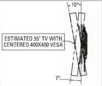
3-D
TILT RANGE
SIDE VIEW - DEPTH
ESPAÑOL
A brand of □ legrand
Thank you for choosing SANUS! Please take a moment to let us know how we did:
Legrand AV Inc.
6436 City West Parkway
Eden Prairie, MN 55344 USA
US: +1 (800) 359-5520
Legrand AV Netherlands B.V.
Franklinstraat 14
6003 DK Weert Netherlands
UK: +44 (0) 800 056 2853
EMEA: +31 (0) 495 580 852
Authorized Representative for the UK
Starline Holding Technology Ltd.
Unit C Island Road
Reading RG2 ORP UK
Legrand AV Inc. and its affiliated corporations and subsidiaries (collectively, "Legrand"), intend to make this manual accurate and complete. However, Legrand AV makes no claim that the information contained herein covers all details, conditions, or variations. Nor does it provide for every possible contingency in connection with the installation or use of this product. The information contained in this document is subject to change without notice or obligation of any kind. Legrand AV makes no representation of warranty, expressed or implied, regarding the information contained herein. Legrand AV assumes no responsibility for accuracy, completeness or sufficiency of the information contained in this document.
©2021 Legrand AV Inc. All rights reserved. SANUS is a brand of Legrand. SANUS and the SANUS logo are registered trademarks of Legrand. All other brand names or marks are used for identification purposes and are trademarks of their respective owners.
Legrand AV Inc. · 6436 City West Parkway · Eden Prairie, MN 55344 USA
6901-602861 00