
2216-20 - Multimeter MILWAUKEE - Free user manual and instructions
Find the device manual for free 2216-20 MILWAUKEE in PDF.

| Product type | Digital multimeter |
| Brand | Milwaukee |
| Model | 2216-20 |
| Category | Multimeter |
| Maximum voltage between terminals and earth | 600 V CAT III |
| Protection rating | IP64 (dust and splash resistant) |
| Drop resistance | 1 meter |
| Power supply | 2 AA batteries (ANSI 15A, IEC LR6) |
| Battery life | Approximately 26 hours with backlight, 240 hours without |
| Protective fuse | 600 V AC/DC, 10 A, fast-acting |
| Display | LCD with LED backlight |
| Measurement functions | AC/DC voltage, AC/DC current, resistance, continuity, capacitance, frequency |
| AC voltage accuracy | ±(1.0% + 3 dgt) (45-500 Hz), ±(2.0% + 3 dgt) (500-1000 Hz) |
| DC voltage accuracy | ±(0.5% + 2 dgt) |
| Resistance accuracy | ±(1.0% + 5 dgt) (up to 6 MΩ), ±(2.0% + 5 dgt) (40 MΩ) |
| Capacitance accuracy | ±(1.9% + 2 dgt) |
| Other functions | Hold, Min/Max, manual/auto ranging, bar graph indicator |
| Backlight | Yes, shuts off after 10 minutes of inactivity |
| Sleep mode | Auto power off after approximately 20 minutes |
| Safety standards | IEC/UL/CSA 61010-1, FCC Part 15B, ICES-003B |
| Warranty | 5 years for the tool |
| Cleaning | Damp cloth with mild soap; avoid solvents |
| Maintenance | Inspect periodically; return to Milwaukee service center for repair |
Frequently Asked Questions - 2216-20 MILWAUKEE
User questions about 2216-20 MILWAUKEE
0 question about this device. Answer the ones you know or ask your own.
Ask a new question about this device
Download the instructions for your Multimeter in PDF format for free! Find your manual 2216-20 - MILWAUKEE and take your electronic device back in hand. On this page are published all the documents necessary for the use of your device. 2216-20 by MILWAUKEE.
USER MANUAL 2216-20 MILWAUKEE
WARNING To reduce the risk of injury, user must read and understand operator's manual.
IMPORTANT SAFETY INSTRUCTIONS
WARNING READ ALL SAFETY WARNINGS AND INSTRUCTIONS.
Failure to follow the warnings and instructions may result in electric shock, fire and/or serious injury, as well as instrument damage and/or damage to the equipment being tested.
Save these instructions - This operator's manual contains important safety and operating instructions for the MILWAUKEE Digital Multimeter. Before using, read this operator's manual and all labels on the Digital Multimeter.
DANGER
Never make measurement on a circuit in which voltage over 600 volts AC/DC rms exists. Use only leads rated CAT III 600V or better.
Do not apply more than the rated voltage, as marked on the Digital Multimeter, between terminals or between any terminal and earth ground. Do not attempt a current measurement when the open voltage is above the fuse protection rating. Suspected open circuit voltage can be checked with voltage function.
Do not attempt to make measurement in the presence of flammable gases. Otherwise, the use of the instrument may cause sparking, which can lead to an explosion.
Never attempt to use the instrument if its surface or your hand is wet.
Do not exceed the maximum allowable input of any measuring range.
Only test on unenergized circuits unless absolutely necessary.
Check meter functionality on a known circuit first. Never assume meter is working. Assume circuits are live until they can be proven de-energized.
Never open the battery cover during a measurement.
Do not ground yourself while measuring. Avoid body contact with earthed or grounded surfaces such as pipes, radiators, ranges and refrigerators.
This instrument is to be used only in its intended applications or conditions. Otherwise, the instrument's safety functions may not work, resulting in serious personal injury and instrument damage.
To reduce the risk of injury from shock and arc blasts, always wear personal protective equipment where live conductors are exposed.
WARNING
Never attempt to make measurement if any abnormal conditions, such as broken case and exposed metal parts are found on the instrument. Comply with local and national safety requirements when working in hazardous locations. Keep fingers behind the guards and away from test lead tips during measurements.
Do not rotate the rotary dial while the test leads are being connected.
Never attempt a voltage measurement with the test lead inserted into the A input terminal.
Verify proper operation on a known source before use or taking action as a result of the indication of the instrument.
Do not install substitute parts, replace fuse or make any modification to the instrument. For repair or re-calibration, return the tool to a factory Service/Sales Support Branch or authorized service station.
Do not try to replace the batteries if the surface of the instrument is wet.
Disconnect all the cords and cables from the object under test and power off the instrument before opening the battery cover for battery replacement.
This tool is designed to be powered by 2-AA batteries properly inserted into the MILWAUKEE Digital Multimeter. Do not attempt to use with any other voltage or power supply.
Install battery according to polarity (+ and -) diagrams.
Do not leave batteries within the reach of children. Do not mix new and used batteries. Do not mix brands (or types within brands) of batteries. Properly dispose of used batteries.
Do not incinerate or dismantle batteries.
Under abusive conditions, liquid may be ejected from the battery, avoid contact. If contact accidentally occurs, flush with water. If liquid contacts eyes, additionally seek medical help. Liquid ejected from the battery may cause irritation or burns.
CAUTION
Set the Rotary Dial to an appropriate position before starting measurement.
Disconnect test leads from test points before changing Rotary Dial functions.
Never connect to a source of voltage with the dial function in OFF/Ω/μW/TA-16 Firmly insert the test leads.
Do not expose the instrument to the direct sun, high temperature and humidity or dew fall.
Altitude 2000m or less. Appropriate operating temperature is within 14°F and 122°F (-10°C and 50°C).
Keep away from excess dust and water.
Be sure to power off the instrument after use. When the instrument will not be in use for a long period, place it in storage after removing the batteries.
Use a damp cloth or neutral detergent for cleaning the instrument. Do not use abrasives or solvents.
FUNCTIONS
| Dial Position Range Resolution Accuracy | ||||
 Voltage AC Voltage AC | 6mV-600mV/6V/60V/600V | 0.1mV/0.001V/0.01V/0.1V | ±(1.0% + 3 dgt) (45~500Hz) ±(2.0% + 3 dgt) (500~1000Hz) | |
 Voltage DC Voltage DC | 600mV/6V/60/600V | 0.1mV/0.001V/0.01V/0.1V | ±(0.5% + 2 dgt) | |
| [Z2WS] HZertz | 2Hz-99.99Hz/999.9Hz/9.999kHz/50kHz | 0.01Hz/0.1Hz/0.001kHz/0.01kHz | ±(0.1% + 2 dgt) Sensitivity: 10Vp-p | |
 Resistance Resistance | 600Ω/6kΩ/60kΩ/600kΩ/6MΩ | 0.1/0.001k/0.01k/0.1k/0.001MΩ | ±(1.0% + 5 dgt) ±(1.0% + 5 dgt) | |
| 40MΩ | 0.01MΩ | ±(2.0% + 5 dgt) | ||
 Continuity Continuity | Cont Buzzer0-600.0Ω | 0.1 Ω | Beeper sounds at 30 Ω and below | |
 Capacitance Capacitance | 100μF / 1000μF | 0.1μF / 1μF | ±(1.9% + 2 dgt) | |
 Current AC Current AC | 0.04A - 6A / 10A | 0.001A/0.01A | ±(1.5% + 3 dgt) (45~500Hz) | |
 Current DC Current DC | 6A/10A | 0.001A/0.01A | ±(1.0% + 3 dgt) | |
Federal Communications Commission Pursuant to part 15.21 of the FCC Rules, you are cautioned that changes or modifications not expressly approved by the party responsible for compliance could void your authority to operate the product. This equipment has been tested and found to comply with the limits for a Class B digital device, pursuant to Part 15 of the FCC Rules. These limits are designed to provide reasonable protection against harmful interference in a residential installation. This equipment generates, uses and can radiate radio frequency energy and, if not installed and used in accordance with the instructions, may cause harmful interference to radio communications. However, there is no guarantee that interference will not occur in a particular installation. If this equipment does cause harmful interference to radio or television reception, which can be determined by turning the equipment off and on, the user is encouraged to try to correct the interference by one or more of the following measures:
- Reorient or relocate the receiving antenna.
- Increase the separation between the equipment and receiver.
- Connect the equipment into an outlet on a circuit different from that to which the receiver is connected.
- Consult the dealer or an experienced radio/TV technician for help.
This device complies with part 15 of the FCC Rules and ISED-Canada's license exempt RSS standards.
Operation is subject to the following two conditions: 1) This device may not cause harmful interference, and 2) This device must accept any interference received, including interference that may cause undesired operation.
*This is a True-RMS instrument. All AC voltage and AC current readings are True-RMS values.
*Input impedance: Voltage DC: 10MΩ; Voltage AC: 10MΩ // less than 100pF
*Overload protection:
Voltage DC, Voltage AC, and Hertz: AC/DC 720V for 10 second
Current DC & Current AC: AC/DC 20A for 10 sec.
Resistance, Continuity, and Capacitance: AC/DC 600V for 10 second
*Maximum measurement time: 1 minute at 10A, rest time 20 minutes minimum
*Minimum frequency measurement is 2Hz
*Minimum AC Current measurement is 0.040A
* For AC Voltage, and AC Current:
Additional Accuracy by Crest Factor (C.F.): Add 6.0% for C.F. 1.0 \~ 2.0
Add 7.0% for C.F. 2.0 \~ 2.5
Add 9.0% for C.F. 2.5 \~ 3.0
Max. Crest Factor: 1.6 for 6600 \~ 5000 digits
2.0 for 5000 \~ 3000 digits
3.0 for 3000 \~ 0 digits
* Measurement accuracy of square wave and truncated waveforms at 1kHz is unspecified.

Operator's Manual

ole insulation

of electric shock

Earth (Ground)

Danger, Warning, or Caution-Consult the operator's manual for additional safety information.

Battery compartment
Cat III
Classification of transient overvoltages, based on nominal line voltage to earth.

Fuse

Do not dispose of this product as unsorted municipal waste.

bean Confirmity Mark

UL Listing for Canada and U.S.
GENERAL SPECIFICATIONS
Cat. No....2216-20
Accuracy is specified for 1 year after calibration, at operating temperatures of 14^ F to 122^ F ( -10^ C to 50^ C), with relative humidity less than 85%, indoor use.
Maximum voltage between any
terminal and earth ground....600V Cat III
Temperature
Operating....14°F to 122°F (-10°C to 50°C)
For Current Measurements ..... 14°F to 104°F
(-10°C to 40°C)
Storage....-40°F to 140°F (-40°C to 60°C)
Operating Altitude 6562 ft (2000 m)
IP Rating
(Ingress Dust & Water Protection)....IP64
Drop Rating 39.4 in (1 m)
Battery 2 AA, ANSI 15A, IEC LR6
Battery Life.....Approx. 26 hours with all lights on, 240 hours without backlight
Fuse 600V AC/DC, 10A fast-acting
Safety Compliances .....IEC/UL/CSA 61010-1,
IEC 61010-2-033 (Meter),
IEC 61010-031+A1 (Probes), EN 61326-1,
FCC Part 15B, ICES-003B (EMC)
Certifications...... cULus, CE
Humidity ......Maximum relative humidity 80%
for temperatures up to 88°F (31°C)
decreasing linearly to 50% relative
humidity at 104 °F (40°C)
Pollution Degree 2
For Indoor Use
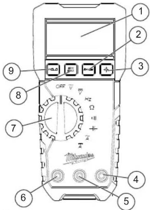
-
Display
-
Range button
-
Backlight button
-
VΩ terminal input
-
COM terminal input
-
A (Amps) terminal input
-
Rotary dial
-
Min/Max button
-
Hold button
-
Accessory bay (on back, not shown)
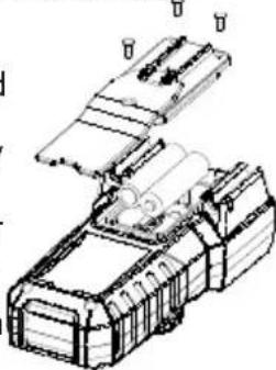
ASSEMBLY
AWARNING To avoid an electrical hazard, turn the rotary dial to OFF and disconnect the test leads before replacing batteries.
Loading/Changing the Batteries
Replace batteries when the low battery indicator □ is displayed.
-
Turn rotary dial to OFF and disconnect the test leads.
-
Unscrew and remove battery door.
-
Insert two (2) AA batteries, according to the polarity marked in the battery compartment
-
Close the battery door an tighten screw securely.
natural_image
Technical line drawing of a mechanical assembly with no visible text or symbolsOPERATION
AWARNING Only use MILWAUKEE test leads with the MILWAUKEE Digital Multimeter. Inspect test leads for continuity before each use. Do not use if the readings are high or noisy.
Before Use
Confirm the rotary dial is set to the correct position, the instrument is set to the correct measurement mode, and the hold function is disabled. Otherwise, desired measurement cannot be made.

LCD Backlight
Press the backlight button *to turn the LCD back-light on and off. The backlight will turn off after about 10 minutes of inactivity and can be turned back on by pressing the backlight button *again.
Making a Measurement

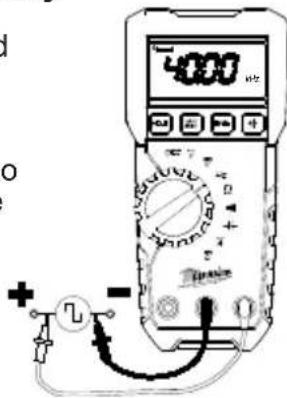
AC Voltage
⚠️DANGER To avoid electrical shock: Never make measurement on a circuit in which voltage over 600 volts AC exists. Do not use with the battery cover removed. Keep fingers behind the guards and away from test lead tips during measurements.
- Set the dial to position.
- Connect the red test lead to the VΩ terminal and the black test lead to the COM terminal.
- Connect the test leads to the circuit under test. The reading is displayed.
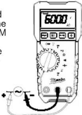
⚠️ CAUTION Readings may fluctuate or be influenced in noisy environment.

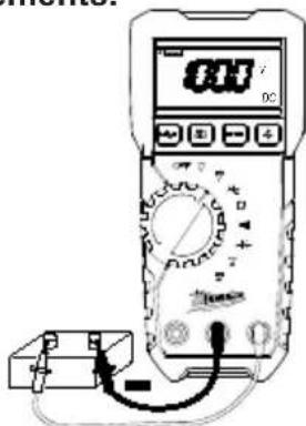
DC Voltage
⚠️DANGER To avoid electrical shock: Never make measurement on a circuit in which voltage over 600 volts DC exists. Do not use with the battery cover removed. Keep fingers behind the guards and away from test lead tips during measurements.
- Set the dial to position.
- Connect the red test lead to the VΩ terminal and the black test lead to the COM terminal.
- Connect the red test lead to the positive (+) side and black test leads to the negative (-) side of the circuit under test. The reading is displayed. A reversed connection is indicated as a negative value.
Hz
Frequency
- Set the dial to Hz position.
- Connect the red test lead to the VΩ terminal and the black test lead to the COM terminal.
- Connect the test leads to the circuit under test. The reading is displayed.
Resistance/Continuity/Capacitance Measurements
ADANGER To reduce the risk of electric shock for Resistance, Continuity, and Capacitance measurements, never use the Digital Multimeter on an energized circuit. Make sure a capacitor is fully discharged before touching or attempting to make a measurement. Do not use with the battery cover removed.

Resistance
- Set the dial to Ω position.
- Connect the red test lead to the VΩ terminal and the black test lead to the COM terminal.
Confirm "OL" is indicated on the display, and then touch the tips of the test leads together to short circuit them to confirm the zero indication and to ensure the meter is working normally. - Connect the test leads to both ends of the resistor under test.
- The reading is displayed.
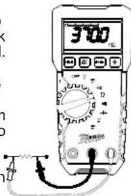
⚠️CAUTION After shorting the test leads, the displayed value may not be zero due to the resistance of test leads themselves.
1111
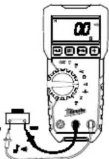
Continuity
- Set the dial to position.
- Connect the red test lead to the VΩ terminal and the black test lead to the COM terminal.
Confirm "OL" is indicated on the display, and then touch the tips of the test leads together to short circuit them to confirm the zero indication (may not be zero due to the resistance of the test leads themselves) with a buzzer sound to ensure the meter is working normally. - Connect the test leads to the both ends of the conductor under test. If the resistance under test is 30 Ω or less, the buzzer will sound.
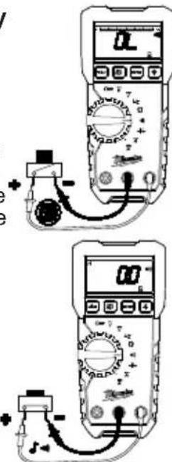

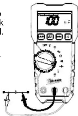
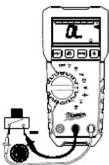
Capacitance
- Set the dial to position.
- Connect the red test lead to the VΩ terminal and the black test lead to the COM terminal.
- Discharge capacitor.
- Connect the test leads to the both ends of the capacitor under test.
- The reading is displayed.

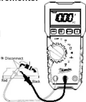
AC Current
⚠️DANGER To avoid electrical shock: Never make measurement on a circuit in which voltage over 600 volts AC exists. Do not use with the battery cover removed. Keep fingers behind the guards and away from test lead tips during measurements.
- Set the dial to position.
- Connect the red test lead to the A terminal and the black test lead to the COM terminal.
- Turn circuit power off, disconnect the circuit, connect the test leads in series with the circuit under test, and then turn circuit power on. The reading is displayed.

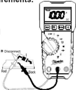
DC Current
⚠️DANGER To avoid electrical shock: Never make measurement on a circuit in which voltage over 600 volts DC exists. Do not use with the battery cover removed. Keep fingers behind the guards and away from test lead tips during measurements.
- Set the dial to position.
- Connect the red test lead to the A terminal and the black test lead to the COM terminal.
- Turn circuit power off, disconnect the circuit, connect the test leads in series with the circuit under test, and then turn circuit power on. The reading is displayed.
Using Bar Graph Display
The bar graph is like the needle on an analog meter, it updates much faster than the digital display. The number of segments indicates the measured value and is relative to the full-scale value of the selected range.
HOLD Button
Hold Function - Freezes the value on the display. Press the HOLD button to freeze the reading. The reading will be held regardless of subsequent variation in input. HOLD is displayed with the reading. To exit Hold mode, press the HOLD button again or change the dial.
SMART HOLD: The meter will beep continuously and the display will flash if the measured signal is 50 counts larger than the display reading. (However, it can not detect across the AC and DC Voltage/Current).
⚠️CAUTION The hold readings of maximum/minimum are released when the digital multimeter enters sleep mode.
MIN/MAX Button
The MIN/MAX recording mode captures the minimum and maximum input values. When a new high or low is detected, the digital multimeter beeps.
Put the digital multimeter in the desired measurement function and range, then press MIN/MAX button to enter MIN/MAX mode, and present readings and MAX and MIN are displayed.
Press MIN/MAX to step through the minimum (MIN displayed), maximum (MAX displayed), and present readings (both MAX and MIN are displayed).
To pause MIN/MAX recording without erasing stored values, press HOLD button and HOLD is displayed. To resume MIN/MAX recording, press HOLD button again.
To exit and erase stored readings, press MIN/MAX-button for two seconds or change the dial.
Range Button
The digital multimeter has both manual and autorange modes. In the autorange mode, the digital multimeter selects the range with the best resolution, and in the manual range mode, you override autorange and select the range yourself. When you turn the digital multimeter on, it defaults to autorange and AUTO is displayed. To enter the manual range mode, press RANGE button, AUTO disappears. In the manual range mode, press RANGE button to increment the range. After the highest range, the meter wraps to the lowest range. To exit manual range, press RANGE button for two seconds or change the dial. The meter returns to autorange and AUTO is displayed.
Sleep Mode
The digital multimeter is automatically powered off about 20 minutes after the last rotary dial or button operation. To reset, rotate the rotary dial to OFF. If the display is still blank when a new dial setting is selected, replace the batteries.
The digital multimeter does use battery power in sleep mode. Be sure to switch the tool to OFF to conserve battery power.
Over-flow indication
Any time the input exceeds the measuring range "OL" or "-OL" is displayed.
Accessory Bay
To install an accessory, slide it into the accessory bay on the back of the digital multimeter. Follow the instructions supplied with the accessory.
MAINTENANCE
WARNING
To reduce the risk of injury, always remove the batteries from the tool before performing any maintenance. Never disassemble the tool. Contact a MILWAUKEE service facility for ALL repairs.
Maintaining Tool
Keep your tool in good repair by adopting a regular maintenance program. After one year, it is recommended to return the tool to a MILWAUKEE service facility for calibration.
If the tool does not start or operate at full power with fully charged batteries, clean the contacts on the battery door. If the tool still does not work properly, return the tool to a MILWAUKEE service facility for repair.
WARNING
To reduce the risk of personal injury and damage, never immerse your tool in liquid or allow a liquid to flow inside them.
Cleaning
Clean dust and debris from any vents. Keep tool clean, dry and free of oil or grease. Use only mild soap and a damp cloth to clean, since certain cleaning agents and solvents are harmful to plastics and other insulated parts. Some of these include gasoline, turpentine, lacquer thinner, paint thinner, chlorinated cleaning solvents, ammonia and household detergents containing ammonia. Never use flammable or combustible solvents around tools.
Repairs
For repairs, return the tool, battery pack and charger to the nearest authorized service center.
ACCESSORIES
WARNING
Use only recommended accessories. Others may be hazardous.
For a complete listing of accessories, go online to www.milwaukeetool.com or contact a distributor.
SERVICE - UNITED STATES
1-800-SAWDUST (1.800.729.3878)
Monday-Friday, 7:00 AM - 6:30 PM CST
or visit www.milwaukeetool.com
Contact Corporate After Sales Service Technical Support with technical, service/repair, or warranty questions.
Email: metproductsupport@milwaukeeetool.com
Become a Heavy Duty Club Member at www.milwaukeeetool.com to receive important notifications regarding your tool purchases.
SERVICE - CANADA
Milwaukee Tool (Canada) Ltd
1.877.948.2360
Monday-Friday, 7:00 AM - 4:30 PM CST
or visit www.milwaukeetool.ca
LIMITED WARRANTY USA & CANADA
MILWAUKEE Test & Measurement Product (including bare tool, M12™ battery pack(s) and battery charger) is warranted to the original purchaser from an authorized MILWAUKEE distributor only to be free from defects in material and workmanship. Subject to certain exceptions, MILWAUKEE will repair or replace any part on this product which, after examination, is determined by MILWAUKEE to be defective in material or workmanship for a period of five (5) years* after the date of purchase. Return of the Test & Measurement tool to the nearest Milwaukee Electric Tool Corporation - factory Service Center, freight prepaid and insured is required. A copy of the proof of purchase should be included with the return product. This warranty does not apply to damage that MILWAUKEE determines to be from repairs made or attempted by anyone other than MILWAUKEE authorized personnel, misuse, alterations, abuse, normal wear and tear, lack of maintenance, or accidents.
* See separate & distinct CORDLESS BATTERY PACK LIMITED WARRANTY statement for the warranty period of the LITHIUM-ION battery pack that ships with Test & Measurement Product. *Alkaline battery that ships with Test & Measurement Product is separately warranted by the alkaline battery manufacturer.
*The warranty period for a Voltage Detector with Work Light – 2201-20, Voltage Detector with LED – 2202-20 or M12™ 2-Beam Plumb Laser – 2230-20 is one (1) year from the date of purchase.
Warranty Registration is not necessary to obtain the applicable warranty on MILWAUKEE product. The manufacturing date of the product will be used to determine the warranty period if no proof of purchase is provided at the time warranty service is requested.
ACCEPTANCE OF THE EXCLUSIVE REPAIR AND REPLACEMENT REMEDIES DESCRIBED HEREIN IS A CONDITION OF THE CONTRACT FOR THE PURCHASE OF EVERY MILWAUKEE PRODUCT. IF YOU DO NOT AGREE TO THIS CONDITION, YOU SHOULD NOT PURCHASE THE PRODUCT. IN NO EVENT SHALL MILWAUKEE BE LIABLE FOR ANY INCIDENTAL, SPECIAL, CONSEQUENTIAL, OR PUNITIVE DAMAGES, OR FOR ANY COSTS, ATTORNEY FEES, EXPENSES, LOSSES OR DELAYS ALLEGED TO BE AS A CONSEQUENCE OF ANY DAMAGE TO, FAILURE OF, OR DEFECT IN ANY PRODUCT INCLUDING, BUT NOT LIMITED TO, ANY CLAIMS FOR LOSS OF PROFITS. SOME STATES DO NOT ALLOW THE EXCLUSION OR LIMITATION OF INCIDENTAL OR CONSEQUENTIAL DAMAGES, SO THE ABOVE LIMITATION OR EXCLUSION MAY NOT APPLY TO YOU. THIS WARRANTY IS EXCLUSIVE AND IN LIEU OF ALL OTHER EXPRESS WARRANTIES, WRITTEN OR ORAL. TO THE EXTENT PERMITTED BY LAW, MILWAUKEE DISCLAIMS ANY IMPLIED WARRANTIES, INCLUDING WITHOUT LIMITATION ANY IMPLIED WARRANTY OF MERCHANTABILITY OR FITNESS FOR A PARTICULAR USE OR PURPOSE; TO THE EXTENT SUCH DISCLAIMER IS NOT PERMITTED BY LAW, SUCH IMPLIED WARRANTIES ARE LIMITED TO THE DURATION OF THE APPLICABLE EXPRESS WARRANTY AS DESCRIBED ABOVE. SOME STATES DO NOT ALLOW LIMITATIONS ON HOW LONG AN IMPLIED WARRANTY LASTS, SO THE ABOVE LIMITATION MAY NOT APPLY TO YOU, THIS WARRANTY GIVES YOU SPECIFIC LEGAL RIGHTS, AND YOU MAY ALSO HAVE OTHER RIGHTS WHICH VARY FROM STATE TO STATE.
This warranty applies to product sold in the U.S.A. and Canada only.
RÈGLES IMPORTANTES DE SÉCURITE
AVERTISSEMENT
LIRE TOUS LES AVER- TISSEMENTS ET
TOUTES LES INSTRUCTIONS.
Pour courant .....-10°C to 40°C (14°F to 104°F)
Attestations......cULus, CE
natural_image
Technical line drawing of a mechanical assembly with no visible text or symbolsUTILISATION
Hz Fréquence

Capacité
Milwaukee Tool (Canada) Ltd 1.877.948.2360
Monday-Friday, 7:00 AM - 4:30 PM CST
www.milwaukeetool.ca
GARANTIE LIMITÉE - AUX ÉTATS-UNIS ET AU CANADA
Federal Communications Commission
natural_image
Technical line drawing of a mechanical assembly with labeled components (no readable text or symbols)FUNCIONAMIENTO
ADVERTENCIA

Capacitancia

Corr. alt.

Corr. cont.
Lunes a Viernes (9am a 6pm)
13135 West Lisbon Road
Brookfield, WI 53005 USA
58142216d3 07802100101Q-02(A)
02/25
Printed in
- IMPORTANT SAFETY INSTRUCTIONS
- WARNING READ ALL SAFETY WARNINGS AND INSTRUCTIONS.
- DANGER
- WARNING
- CAUTION
- GENERAL SPECIFICATIONS
- ASSEMBLY
- AWARNING To avoid an electrical hazard, turn the rotary dial to OFF and disconnect the test leads before replacing batteries.
- OPERATION
- Before Use
- LCD Backlight
- Making a Measurement
- AC Voltage
- DC Voltage
- Hz
- Frequency
- Resistance/Continuity/Capacitance Measurements
- Resistance
- 1111
- Continuity
- Capacitance
- AC Current
- ⚠️DANGER To avoid electrical shock: Never make measurement on a circuit in which voltage over 600 volts AC exists. Do not use with the battery cover removed. Keep fingers behind the guards and away from test lead tips during measurements.
- DC Current
- ⚠️DANGER To avoid electrical shock: Never make measurement on a circuit in which voltage over 600 volts DC exists. Do not use with the battery cover removed. Keep fingers behind the guards and away from test lead tips during measurements.
- Using Bar Graph Display
- HOLD Button
- ⚠️CAUTION The hold readings of maximum/minimum are released when the digital multimeter enters sleep mode.
- MIN/MAX Button
- Range Button
- Sleep Mode
- Over-flow indication
- Accessory Bay
- MAINTENANCE
- Maintaining Tool
- Cleaning
- Repairs
- ACCESSORIES
- SERVICE - UNITED STATES
- 1-800-SAWDUST (1.800.729.3878)
- SERVICE - CANADA
- Milwaukee Tool (Canada) Ltd
- LIMITED WARRANTY USA & CANADA
- RÈGLES IMPORTANTES DE SÉCURITE
- AVERTISSEMENT
- TOUTES LES INSTRUCTIONS.
- UTILISATION
- Hz Fréquence
- Capacité
- Milwaukee Tool (Canada) Ltd 1.877.948.2360
- GARANTIE LIMITÉE - AUX ÉTATS-UNIS ET AU CANADA
- Federal Communications Commission
- FUNCIONAMIENTO
- ADVERTENCIA
- Capacitancia
- Corr. alt.
- Corr. cont.
Brand : MILWAUKEE
Model : 2216-20
Category : Multimeter