
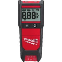
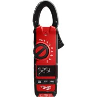
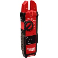
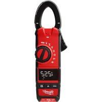
M12 223920NST - Multimeter MILWAUKEE - Free user manual and instructions
Find the device manual for free M12 223920NST MILWAUKEE in PDF.

| Product Type | Digital Clamp Multimeter |
| Brand | Milwaukee |
| Model | M12 223920NST |
| Power Supply | M12 Lithium-ion Battery |
| AC Current Range | 60/600 A (2238-20) or 60/600/1000 A (2239-20) |
| DC Current Range | 60/600 A (2238-20) or 60/600/1000 A (2239-20) |
| AC Voltage Range | 600 V / 1000 V |
| DC Voltage Range | 600 V / 1000 V |
| Resistance | 600 Ω to 600 kΩ |
| Capacitance | 400 μF / 4000 μF |
| Temperature (2238-20) | -40°C to 538°C (-40°F to 1000°F) |
| Frequency (2239-20) | Up to 60 kHz |
| Special Functions | Non-contact voltage detection, inrush current, MIN/MAX, HOLD, ZERO |
| Display | Digital LCD |
| Safety | CAT III 1000V, CAT IV 600V, double insulation |
| Jaw Opening | 33 mm (1.3 inch) |
| Operating Temperature | -10°C to 50°C (14°F to 122°F) |
| Operating Humidity | 0% to 85% RH |
| Maximum Altitude | 2,000 meters |
| Cleaning | Damp cloth and mild soap |
| Warranty | 5 years (tool), 2 years (battery) |
Frequently Asked Questions - M12 223920NST MILWAUKEE
User questions about M12 223920NST MILWAUKEE
0 question about this device. Answer the ones you know or ask your own.
Ask a new question about this device
Download the instructions for your Multimeter in PDF format for free! Find your manual M12 223920NST - MILWAUKEE and take your electronic device back in hand. On this page are published all the documents necessary for the use of your device. M12 223920NST by MILWAUKEE.
USER MANUAL M12 223920NST MILWAUKEE
IMPORTANT SAFETY INSTRUCTIONS

WARNING READ ALL SAFETY WARNINGS AND INSTRUCTIONS.
Failure to follow the warnings and instructions may result in electric shock, fire and/or serious injury, as well as instrument damage and/or damage to the equipment being tested.
Save these Instructions - This operator's manual contains important safety and operating instructions for the MILWAUKEE Clamp Meters. Before using, read this operator's manual, your battery pack and charger operator's manual, and all labels on the battery pack, charger and Clamp Meters.

DANGER
Never make measurement on a circuit in which voltage over 1000V exists. Use only leads rated 1000V or better.
Do not attempt to make measurement in the presence of flammable gasses. Otherwise, the use of the instrument may cause sparking, which can lead to an explosion.
Transformer jaw tips are designed not to short the circuit under test. If equipment under test has exposed conductive parts, however, extra precaution should be taken to minimize the possibility of shorting.
Never attempt to use the instrument if its surface or your hand is wet.
Do not exceed the maximum allowable input of any measuring range.
Only test on unenergized circuits unless absolutely necessary.
Check tool functionality on a known circuit first. Never assume tool is working. Assume circuits are live until they can be proven de-energized.
Do not ground yourself while measuring. Avoid body contact with earthed or grounded surfaces such as pipes, radiators, ranges and refrigerators.
Never remove the battery pack during a measurement.
This instrument is to be used only in its intended applications or conditions. Otherwise, the instrument's safety functions may not work, resulting in serious personal injury and instrument damage.
To reduce the risk of injury from shock and arc blasts, always wear personal protective equipment where live conductors are exposed.

WARNING
Never attempt to make measurement if any abnormal conditions, such as broken case and exposed metal parts are found on the instrument.
Do not rotate the Rotary Dial while the test leads are being connected.
Verify proper operation on a known source before use or taking action as a result of the indication of the instrument.
Do not install substitute parts or make any modification to the instrument. For repair or recalibration, return the tool to a factory Service/Sales Support Branch or authorized service station.
Do not try to replace the battery pack if the surface of the instrument is wet.
Disconnect all the cords and cables from the object under test and power off the instrument before removing or inserting the battery pack.
Recharge only with the charger specified by the manufacturer. A charger that is suitable for one type of battery pack may create a risk of fire when used with another battery pack.
Use the meter only with specifically designated battery packs. Use of any other battery packs may create a risk of injury and fire.
When battery pack is not in use, keep it away from other metal objects like paper clips, coins, keys, nails, screws, or other small metal objects that can make a connection from one terminal to another. Shorting the battery terminals together may cause burns or a fire.
Under abusive conditions, liquid may be ejected from the battery, avoid contact. If contact accidentally occurs, flush with water. If liquid contacts eyes, additionally seek medical help. Liquid ejected from the battery may cause irritation or burns.

CAUTION
Set the Rotary Dial to an appropriate position before starting measurement. Firmly insert the test leads.
Disconnect the test leads from the instrument for current measurement.
Do not expose the instrument to the direct sun, high temperature and humidity or dew fall. Altitude 2000m or less. Appropriate operating temperature is within -10°C and 50°C.
This instrument isn't dust & water proofed. Keep away from dust and water.
Be sure to power off the instrument after use. When the instrument will not be in use for a long period, place it in storage after removing the battery pack.
Use a damp cloth or neutral detergent for cleaning the instrument. Do not use abrasives or solvents.
Functions
| Dial Position Range Resolution Accuracy | ||||
| Current AC | 2238-20: 60/600 A 0.01/0.1 A | ±1.9%rdg ±5dgts, 50Hz/60Hz±3.0%rdg ±5dgts, 45Hz to 500Hz* Add 2% at CF>2 | ||
| 2239-20: 60/600/1000 A 0.01/0.1/1 A | ||||
| Current DC | 2239-20: 60/600/1000 A 0.01/0.1/1 A ±2%rdg±5dgt | |||
| Voltage AC | 600 V 0.1 V | ±1.2%rdg ±5dgts, 50Hz/60Hz±1.8%rdg ±5dgts, 45Hz to 500Hz | ||
| 1000 V 1 V | ||||
| Voltage DC | 600 V 0.1 V | ±1%rdg±2dgt | ||
| 1000 V 1 V | ||||
| Ω | Resistance | 600 Ω/6000 Ω/60 kΩ/600 kΩ | 0.1 Ω/1 Ω/10 Ω/0.1 kΩ | ±1%rdg±2dgt |
| Continuity | 600.0Ω | 0.1 Ω | Buzzer sounds at 30Ω or less | |
| Capacitance | 400μF/4000μF | 0.1μF/1μF | ±2.5%±20dgtup to 60μF | |
| uA DC | 2238-20: 600.0 uA | 0.1uA | ±1.5%rdg±5dgt | |
| Ω | Temperature | 2238-20: -40°C - 538°C | 0.1°C | ±1%±10dgt |
| 2238-20: -40°F - 1000°F | 0.1°F | ±1%±18dgt | ||
| Hz | Hertz | 2239-20:ACA: 600 Hz, 6 kHz | 0.1 Hz, 1Hz | ±1%rdg±1dgtSensitivity: Amps 5A RMS;Volts - 30V RMSMinimum Herts measurement is 10Hz |
| 2239-20:ACV: 600 Hz, 6 kHz, 60 kHz | 0.1 Hz, 1 Hz, 10 Hz | |||
• These instruments are True-RMS sensing. All voltage and current readings are True-RMS values.
• Input impedance:
Voltage DC: 1MΩ
Voltage AC: 1MΩ
• Overload protection:
Voltage AC / Voltage DC range: 1200V AC RMS
- Clamp current range:
720A AC RMS / DC 10sec (Cat. No. 2238-20 only)
1200A AC RMS / DC 10sec (Cat. No. 2239-20 only)
- Inrush (Cat. No. 2239-20 only): integration time less than or equal to 100ms
General Specifications
Accuracy is specified for 1 year after calibration, at operating temperatures of 18^ C to 28^ C ( 64^ F to 82^ F), with relative humidity at 0 % to 85 %.
Maximum voltage between any terminal and earth ground .... 1000 V
Jaw Opening (maximum conductor size) .... approx. 1.3" (33 mm)
Temperature
Operating: -10°C to 50°C (14°F to 122°F) Storage: -40°C to 60°C (-40°F to 140°F)
Temperature Coefficient .... 0.1 x (specified accuracy)/°C (<18°C or >28°C)
Operating Altitude.... 2,000 meters
Drop Test .... 1 meter
Safety Compliances .... EN61010-1, UL 61010-1, EN61010-031 (Probes), IEC 61010-2-32 (Clamp Assemblies), IEC/EN 61010-1 2nd Edition for measurement Category III, 1000 V, Category IV, 600 V, Pollution Degree 2, EMC EN61326-1
Certifi cations .... cULus, CE
Voltage: 12 DC Li-Ion, MILWAUKEE Battery Pack Cat. Nos. 48-11-2401, 48-11-2402
Battery run time: Greater than 12 hrs with all functions
Symbology


To reduce the risk of injury, user must read operator's manual.
Double insulation
Risk of electric shock
Indicates that this instrument can clamp on bare conductors when measuring a voltage corresponding to the applicable measurement category, which is marked next to this symbol.
Earth
Danger, Warning, or Caution - Consult the operators manual for additional safety information.
Volts Direct Current
European Conformity Mark
Underwriters Laboratories, Inc., United States and Canada
Classifi cation of transient overvoltages, based on nominal line voltage to earth.
Do not dispose of this product as unsorted municipal waste.
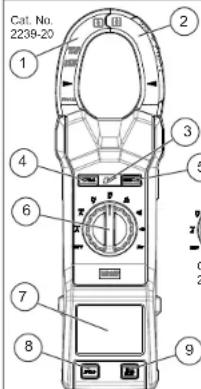
FUNCTIONAL DESCRIPTION
-
Current sensing jaws
-
NCVD sensing area
-
NCVD indicator
-
°F/°C button (2238-20)
Zero button (2239-20)
-
Inrush button (2239-20)
-
Rotary Dial
- Display
- Hold button
- Min/Max button
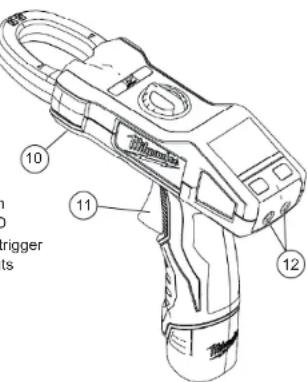
- Worklight LED
- Jaw opening trigger
- Terminal inputs
[Non-Text]
![MILWAUKEE M12 223920NST - [Non-Text] - 1](/content/2026/03/572036/images/7b9a542825f4d8b7132058eee3ad77b67557cb5f5c129258f4a0b0de8e3c3c26.jpg)
WARNING Recharge only with the char- specified for the battery. For specific char- nstructions, read the operator's manual lied with your charger and battery.
Inserting/Removing the Battery
To remove the battery, use a fl at screwdriver to pry open the lock latch. Push in the release buttons and pull the battery pack away from the tool. To insert the battery
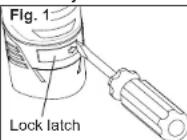
slide the pack into the body of the tool. Make sure it latches securely into place. Press in the lock latch to lock the battery in place.
OPERATION

WARNING Always turn the Rotary to OFF before Inserting or removing es. Only use accessories specifically amended for this tool. Others may be rdous.

WARNING
Only use MILWAUKEE test leads with the MILWAUKEE Clamp Meters.
Inspect test leads before each use. Use clamp meter to run a continuity test.
Before Use
Confirm the Rotary Dial is set to the correct position, the instrument is set to the correct measurement mode, and the Data hold function is disabled. Otherwise, desired measurement cannot be made.
Making a Measurement

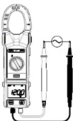
AC Current

DANGER To avoid electrical shock: or make measurement on a circuit in h voltage over 1000V exists. Clamp tips designed not to short the circuit under if equipment under test has exposed reactive parts, however, extra precaution could be taken to minimize the possibility sorting.
Disconnect the test leads from the instrument for current measurement.
- Set the Rotary Dial to position. AC mark is displayed.
- Press the jaw opening trigger to open the jaws and clamp them onto the conductor under test. The reading is displayed.
NOTE: Do not clamp over 2 or more wires at the same time. Irregular results will occur.

CAUTION Maximum conductor size
Is about 1.3" diameter. During measurement, keep the jaws fully closed to ensure accurate measurements.

DC Current (Cat. No. 2239-20 only)

DANGER To avoid electrical shock:
Never make measurement on a circuit in which voltage over 1000V exists.
- Set the Rotary Dial to position. DC mark is displayed.
- With the jaws closed and without clamping them around a conductor, press the ZERO key to zero adjust the display.
- Press the jaw opening trigger to open the jaws and clamp them around the conductor under test. NOTE: Do not clamp over 2 or more wires at the same time. Irregular results will occur.
- The reading is displayed.
- Press the ZERO key again to release the ZERO function.

CAUTION When current flows from
the display side to the underside of the meter, the polarity is positive; flow from underside to display side, the polarity is negative.

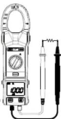
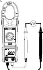
AC Voltage
DANGER To avoid electrical shock: Never make measurement on a circuit in which voltage over 1000V exists. Keep fi ngers away from jaws during measurements.
- Set the Rotary Dial to position.
- Connect the red test lead to the VΩ terminal and the black test lead to the COM terminal.
- Connect the test leads to the circuit under test. The reading is displayed.

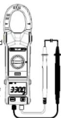
DC Voltage
DANGER To avoid electrical shock: Never make measurement on a circuit in which voltage over 1000V exists. Keep fi ngers away from jaws during measurements.
- Set the Rotary Dial to position.
- Connect the red test lead to the VΩ terminal and the black test lead to the COM terminal.
- Connect the red test lead to the positive (+) side and black test leads to the nega-
tive (-) side of the circuit under test. The reading is displayed. A reversed connection is indicated as a negative value.
Resistance/Continuity/Capacitance Measurements
DANGER To reduce the risk of electric shock for Resistance, Continuity, and Capacitance measurements, never use the meter on an energized circuit. Make sure a capacitor is fully discharged before touching or attempting to make a measurement.

Resistance
-
Set the Rotary Dial to position.
-
Connect the red test lead to the VΩ terminal and the black test lead to the COM terminal.
Confir m "OL" is indicated on the display, and then short-circuit the tips of test leads to make the indication zero.
- Connect the test leads to the both ends of the resistor under test.
- The reading is displayed.

CAUTION After shorting the test leads, isplayed value may not be zero due to the tance of test leads themselves.

Continuity
- Set the Rotary Dial to position.
- Connect the red test lead to the VΩ terminal and the black test lead to the COM terminal.
Confir m "OL" is indicated on the display, and then short-circuit the tips of test leads to make the indication zero. A buzzer will sound. - Connect the test leads to the both ends of the conductor under test. If the resistance t or less, the buzzer will sound

Capacitance
- Set the Rotary Dial to position.
- Connect the red test lead to the VΩ terminal and the black test lead to the COM terminal.
- Discharge capacitor.
- Connect the test leads to the both ends of the capacitor under test.
- The reading is displayed.
under test is 30 Ω

DC Current (Cat. No. 2238-20 only)

DANGER To avoid electrical shock: or make measurement on a circuit in voltage over 1000V exists.
- Set the Rotary Dial to position. DC mark is displayed.
- Connect the red test lead to the VΩ terminal and the black test lead to the COM terminal. Contact the red test lead to the flame sensor probe and the black test lead to the control module.
- Turn on the heating unit. The reading is displayed.
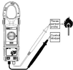

WARNING Never connect the erature Probe to an energized circuit.

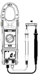
Temperature (Cat. No. 2238-20 only)
- Set the Rotary Dial to position.
- Connect the K-type Temperature Probe to the input terminal. The positive (+) side of Probe should be connected to VΩ.
- Place the probe sensor in the desired location.
- The reading is displayed.
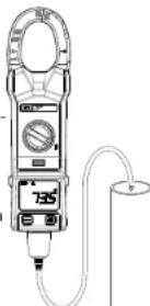

CAUTION When the Rotary Dial is set, a L should be displayed. If anything else is played, something may be wrong with the r. Stop using the meter immediately.

Frequency (Cat. No. 2239-20 only)
- Set the Dial to Hz position.
- Voltage: Connect the red test lead to the VΩ terminal and the black test lead to the COM terminal. Connect the test leads to the circuit under test. The reading is displayed.
Current: Press the jaw opening trigger to open the jaws and clamp them onto the conductor under test. The reading is displayed.
NOTE: Do not clamp over 2 or more wires at the same time. Irregular results will occur.
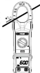

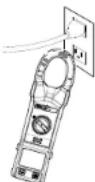
Non-Contact Voltage Detection (NCVD)

DANGER The LED may not be
displayed due to installation condition of electrical circuit or equipment. Never touch the circuit under test to avoid possible danger even if the LED for NCVD is not displayed.
Check the functionality of LED on a well-known power supply prior to measurement. When the LED doesn't light up, do not make measurement.
NCVD indication is affected by external voltage, and how the meter is held or placed.
When the meter is on in any function, the non-contact voltage detector will indicate with a Red LED on the display when an electric fi eld exceeding 90V is detected. Place the edge of the jaw labeled "Voltage Detector" near the electric fi eld.
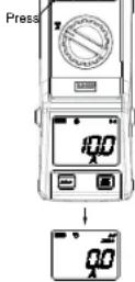
HOLD Function
Data Hold Function - Freezes the value on the display. Press the "HOLD" button to freeze the reading. The reading will be held regardless of subsequent variation in input. HOLD is displayed with the reading. To exit Data Hold mode, press the HOLD button again. Hold is not available when using the Inrush Function.
MIN/MAX Function

CAUTION Make a measurement press the MIN/MAX button after an appropriate range is selected by the auto-ting function.
The MIN/MAX recording mode captures the minimum and maximum input values.
Set the dial to to the desired measurement function. Make a measurement and press the MIN/MAX button. The meter will capture the MIN and MAX readings. Press the MIN/MAX button to toggle between the captured MIN, MAX and present readings. MAXMIN flashes when the present reading is displayed.
To exit and erase stored readings, press the MIN/MAX button for two seconds or change the dial.
If MIN/MAX is active, all function buttons are unavailable except HOLD.
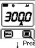
ZERO Function
(Cat. No. 2239-20 only)
AC Current A DC Current :A When the LCD doesn't read ZERO while the Jaws are closed press the ZERO Button to indicate ZERO before starting a measurement. With the jaws closed and without clamping them around a conductor, press the ZERO key to zero adjust the display.
The "ZERO" mark appears on the LCD to indicate the ZERO Function is activated.
°F / °C (Cat. No. 2238-20 only)
To switch between Fahrenheit or Celsius, press the °F / °C button.

DANGER To avoid electrical shock: r make measurement on a circuit in voltage over 1000V exists.
Inrush Function (Cat. No. 2239-20 only)
Inrush current measurement allows for measuring the sharp peak in current upon motor startups. Lasting only part of a second, MILWAUKEE's Inrush function captures and displays the first 100 milliseconds of current at motor startup.
Power off the system under test.1
Press the jaw opening trigger to open the jaws and clamp them onto the conductor under test.
NOTE: Do not clamp over 2 or more wires at the same time. Irregular results will occur.
Set the Rotary 3.
Dial to or
position. AC or DC
mark is displayed.
Press the INRUSH 4. button.
Power on the 5. system under te


Over-flow indication
Any time the input exceeds the measuring range "OL" or "-OL" is displayed.

Worklight LED ON/OFF
To turn the light on and off, pull the trigger.
Sleep Mode

CAUTION The Data Hold readings are set when the meter enters Sleep Mode.
The clamp meter is automatically powered off in about 20 min after the last Rotary Dial or button operation. To reset, rotate the Rotary Dial or pull the trigger. If the display is still blank when a new Rotary Dial setting is selected, charge the battery pack. To disable the sleep function, turn the tool off. Press and hold the HOLD button and turn on the meter. After the meter "beeps", release the HOLD button. The meter will beep again and the clock symbol will be removed from the display.
The clamp meter does use battery power in sleep mode. Be sure to switch the tool to OFF to conserve battery power.
MAINTENANCE

WARNING To reduce the risk of injury, you unplug the charger and remove the very pack from the charger or tool before forming any maintenance. Never disable the tool, battery pack or charger. Fact a MILWAUKEE service facility for repairs.
Maintaining Tool
Keep your tool, battery pack and charger in good repair by adopting a regular maintenance program. After six months to one year, depending on use, return the tool, battery pack and charger to a MILWAUKEE service facility service.
If the tool does not start or operate at full power with a fully charged battery pack, clean the contacts on the battery pack. If the tool still does not work properly, return the tool, charger and battery pack, to a MILWAUKEE service facility for repairs.

WARNING To reduce the risk of per-1 Injury and damage, never immerse your battery pack or charger in liquid or allow aid to flow inside them.
Cleaning
Clean dust and debris from charger and tool vents. Keep tool handles clean, dry and free of oil or grease. Use only mild soap and a damp cloth to clean the tool, battery pack and charger since certain cleaning agents and solvents are harmful to plastics and other insulated parts. Some of these include gasoline, turpentine, lacquer thinner, paint thinner, chlorinated cleaning solvents, ammonia and household detergents containing ammonia. Never use fl ammable or combustible solvents around tools.
Repairs
For repairs, return the tool, battery pack and charger to the nearest service center listed on the back cover of this operator's manual.
ACCESSORIES

WARNING Always remove battery before changing or removing accesses. Only use accessories specifically amended for this tool. Others may be wordous.
For a complete listing of accessories refer to your MILWAUKEE Electric Tool catalog or go online to www.milwaukeetool.com. To obtain a catalog, contact your local distributor or a service center listed on the back cover of this operator's manual.
FIVE YEAR TOOL
LIMITED WARRANTY
MILWAUKEE Test & Measurement Products (including bare tool, li-ion battery pack(s) and battery charger but excluding alkaline batteries) are warranted to the original purchaser only to be free from defects in material and workmanship. Subject to certain exceptions, MILWAUKEE will repair or replace any part on this product which, after examination, is determined by MILWAUKEE to be defective in material or workmanship for a period of five (5) years* after the date of purchase. Return the Test & Measurement tool and a copy of proof of purchase to the nearest Milwaukee Electric Tool Corporation - factory Service Center. This warranty does not apply to damage that MILWAUKEE determines to be from repairs made or attempted by anyone other than MILWAUKEE authorized personnel, misuse, alterations, abuse, normal wear and tear, lack of maintenance, or accidents.
*The warranty period for the LITHIUM-ION battery pack that ships with the Test & Measurement tool is two (2) years from the date of purchase. *Alkaline battery that ships with Test & Measurement tool is separately warranted by the battery manufacturer. *The warranty period for a NON-CONTACT VOLTAGE DETECTOR - 2201 20 is one (1) year from the date of purchase.
Warranty Registration is not necessary to obtain the applicable warranty on MILWAUKEE product. The manufacturing date of the product will be used to determine the warranty period if no proof of purchase is provided at the time warranty service is requested.
ACCEPTANCE OF THE EXCLUSIVE REPAIR AND REPLACEMENT REMEDIES DESCRIBED HEREIN IS A CONDITION OF THE CONTRACT FOR THE PURCHASE OF EVERY MILWAUKEE PRODUCT. IF YOU DO NOT AGREE TO THIS CONDITION, YOU SHOULD NOT PURCHASE THE PRODUCT. IN NO EVENT SHALL MILWAUKEE BE LIABLE FOR ANY INCIDENTAL, SPECIAL, CONSEQUENTIAL OR PUNITIVE DAMAGES, OR FOR ANY COSTS, ATTORNEY FEES, EXPENSES, LOSSES OR DELAYS ALLEGED TO BE AS A CONSEQUENCE OF ANY DAMAGE TO, FAILURE OF, OR DEFECT IN ANY PRODUCT INCLUDING, BUT NOT LIMITED TO, ANY CLAIMS FOR LOSS OF PROFITS. THIS WARRANTY IS EXCLUSIVE AND IN LIEU OF ALL OTHER WARRANTIES OR CONDITIONS, WRITTEN OR ORAL, EXPRESSED OR IMPLIED. WITHOUT LIMITING THE GENERALITY OF THE FOREGOING, MILWAUKEE DISCLAIMS ANY IMPLIED WARRANTY OF MERCHANTABILITY OR FITNESS FOR A PARTICULAR USE OR PURPOSE, AND ALL OTHER WARRANTIES.
This warranty applies to product sold in the U.S.A., Canada and Mexico only.
RÈGLES IMPORTANTES DE SÉCURITÉ

AVERTISSEMENT LIRE TOUS LES AVERTISSEMENTS ET TOUTES LES
Attestations .... cULus, CE
Tension : 12 V c.c. Li-Ion, MILWAUKEE No de Cat. 48-11-2401, 48-11-2402

UNITED STATES - MILWAUKEE Service
MILWAUKEE prides itself in producing a premium quality product that is NOTHING BUT HEAVY DUTY®. Your satisfaction with our products is very important to us! If you encounter any problems with the operation of this tool, or you would like to locate the factory Service/Sales Support Branch or authorized service station nearest you, please call...
1-800-SAWDUST
(1.800.729.3878)
Monday-Friday
7:00 AM - 6:30 PM
Central Time
or visit our website at
www.milwaukeetool.com
For service information, use the 'Service Center Search' icon found in the 'Parts & Service' section.
Additionally, we have a nationwide network of authorized Distributors ready to assist you with your tool and accessory needs. Check your "Yellow Pages" phone directory under "Tools-Electric" for the names & addresses of those nearest you or see the "Where To Buy" section of our website.
Contact our Corporate After Sales Service Technical Support about ...
•Technical Questions
•Service/Repair Questions
•Warranty
call: 1-800-SAWDUST
fax: 1.800.638.9582
email: metproductsupport@milwaukeeetool.com
Register your tool online at
www.milwaukeeetool.com and...
• receive important notifications regarding your purchase
- ensure that your tool is protected under the warranty
• become a HEAVY DUTY club member
Canada - Service MILWAUKEE
Milwaukee Electric Tool (Canada) Ltd
755 Progress Avenue
Scarborough, Ontario M1H 2W7
Dr. Andrade 140 Local B, Col. Doctores
MILWAUKEE ELECTRIC TOOL CORPORATION
13135 West Lisbon Road • Brookfi eld, Wisconsin, U.S.A. 53005
58-14-2238d2
8/09
Printed in China
- IMPORTANT SAFETY INSTRUCTIONS
- WARNING READ ALL SAFETY WARNINGS AND INSTRUCTIONS.
- DANGER
- WARNING
- CAUTION
- General Specifications
- Symbology
- FUNCTIONAL DESCRIPTION
- [Non-Text]
- Inserting/Removing the Battery
- OPERATION
- Before Use
- Making a Measurement
- AC Current
- AC Voltage
- DC Voltage
- Resistance/Continuity/Capacitance Measurements
- Resistance
- Continuity
- Capacitance
- DC Current (Cat. No. 2238-20 only)
- Frequency (Cat. No. 2239-20 only)
- Non-Contact Voltage Detection (NCVD)
- DANGER The LED may not be
- HOLD Function
- MIN/MAX Function
- ZERO Function
- (Cat. No. 2239-20 only)
- °F / °C (Cat. No. 2238-20 only)
- Inrush Function (Cat. No. 2239-20 only)
- Over-flow indication
- Worklight LED ON/OFF
- Sleep Mode
- MAINTENANCE
- Maintaining Tool
- Cleaning
- Repairs
- ACCESSORIES
- FIVE YEAR TOOL
- LIMITED WARRANTY
- RÈGLES IMPORTANTES DE SÉCURITÉ
- AVERTISSEMENT LIRE TOUS LES AVERTISSEMENTS ET TOUTES LES
- UNITED STATES - MILWAUKEE Service
- 1-800-SAWDUST
- Register your tool online at
- Canada - Service MILWAUKEE
- MILWAUKEE ELECTRIC TOOL CORPORATION
Brand : MILWAUKEE
Model : M12 223920NST
Category : Multimeter