
223720 - Multimeter MILWAUKEE - Free user manual and instructions
Find the device manual for free 223720 MILWAUKEE in PDF.

| Product Type | Clamp Multimeter |
| Brand | Milwaukee |
| Model | 223720 |
| Power Supply | 2 AA batteries (NEDA 15A, IEC LR6) |
| Battery Life | Approximately 30 hours with all indicators on |
| Measurement Category | CAT III 600 V |
| Maximum Measurable Voltage | 600 V AC/DC |
| Measurable AC Current | 0–600 A AC (clamp) |
| Measurable DC Current | 0–600 A DC (clamp, depending on model) |
| Measurable Resistance | Up to 6 kΩ |
| Measurable Capacitance | 0.01 nF – 4000 μF |
| Measurable Temperature | -40 °C to 400 °C (depending on model) |
| Measurable Frequency | Up to 10 kHz (depending on model) |
| Jaw Opening | Approximately 33 mm (1.3 inches) |
| Display | LCD with backlight |
| Special Functions | MIN/MAX, Zero, Hold, Non-contact voltage detection (NCVD) |
| Dimensions | Not specified, approximately 250 x 80 x 40 mm (estimate) |
| Weight | Approximately 400 g (estimate) |
| Operating Temperature | -10 °C to 50 °C |
| Maximum Altitude | 2000 m |
| Maintenance and Cleaning | Damp cloth with mild soap; do not immerse |
| Safety | UL/CSA 61010-1, POLLUTION DEGREE 2 |
| Spare Parts and Repairability | Entrust to an authorized MILWAUKEE service center; use MILWAUKEE test leads |
| Warranty | 5 years (parts and labor) except exceptions |
Frequently Asked Questions - 223720 MILWAUKEE
User questions about 223720 MILWAUKEE
0 question about this device. Answer the ones you know or ask your own.
Ask a new question about this device
Download the instructions for your Multimeter in PDF format for free! Find your manual 223720 - MILWAUKEE and take your electronic device back in hand. On this page are published all the documents necessary for the use of your device. 223720 by MILWAUKEE.
USER MANUAL 223720 MILWAUKEE
WARNING To reduce the risk of injury, user must read and understand operator's manual.
IMPORTANT SAFETY INSTRUCTIONS
WARNING
READ ALL SAFETY WARNINGS AND INSTRUCTIONS.
Failure to follow the warnings and instructions may result in electric shock, fire and/or serious injury, as well as instrument damage and/or damage to the equipment being tested.
Save these instructions - This operator's manual contains important safety and operating instructions for the MILWAUKEE Clamp Meters. Before using, read this operator's manual and all labels on the Clamp Meters.
DANGER
Never make measurement on a circuit in which voltage over AC600V exists. Use only leads rated 600V or better.
Do not attempt to make measurement in the presence of flammable gasses. Otherwise, the use of the instrument may cause sparking, which can lead to an explosion.
Transformer jaw tips are designed not to short the circuit under test. If equipment under test has exposed conductive parts, however, extra precaution should be taken to minimize the possibility of shorting.
Never attempt to use the instrument if its surface or your hand is wet.
Do not exceed the maximum allowable input of any measuring range.
Only test on unenergized circuits unless absolutely necessary.
Check tool functionality on a known circuit first. Never assume tool is working. Assume circuits are live until they can be proven de-energized.
Do not ground yourself while measuring. Avoid body contact with earthed or grounded surfaces such as pipes, radiators, ranges and refrigerators. Never open the Battery cover during a measurement. The instrument is to be used only in its intended applications or conditions. Otherwise, safety functions equipped with the instrument doesn't work, and instrument damage or serious personal injury may be caused.
To reduce the risk of injury from shock and arc blasts, always wear personal protective equipment where live conductors are exposed.
WARNING
Never attempt to make measurement if any abnormal conditions, such as broken case and exposed metal parts are found on the instrument.
Do not rotate the Rotary Dial while the test leads are being connected.
Verify proper operation on a known source before use or taking action as a result of the indication of the instrument.
Do not install substitute parts or make any modification to the instrument. For repair or re-calibration, return the tool to a factory Service/Sales Support Branch or authorized service station.
Do not try to replace the batteries if the surface of the instrument is wet.
Disconnect all the cords and cables from the object under test and power off the instrument before opening the Battery Cover for Battery replacement.
This tool is designed to be powered by 2-AA batteries properly inserted into the MILWAUKEE Clamp Meters. Do not attempt to use with any other voltage or power supply.
Install battery according to polarity (+ and −) diagrams. Do not leave batteries within the reach of children.
Do not mix new and used batteries. Do not mix brands (or types within brands) of batteries.
Properly dispose of used batteries.
Do not incinerate or dismantle batteries.
Under abusive conditions, liquid may be ejected from the battery, avoid contact. If contact accidentally occurs, flush with water. If liquid contacts eyes, additionally seek medical help. Liquid ejected from the battery may cause irritation or burns.
CAUTION
Set the Rotary Dial to an appropriate position before starting measurement.
Firmly insert the test leads.
Disconnect the test leads from the instrument for current measurement.
Do not expose the instrument to the direct sun, high temperature and humidity or dew fall.
Altitude 2000m or less. Appropriate operating temperature is within -10°C and 50°C.
This instrument isn't dust & water proofed. Keep away from dust and water.
fBe sure to power off the instrument after use. When the instrument will not be in use for a long period, place it in storage after removing the batteries.
Use a cloth dipped in water or neutral detergent for cleaning the instrument. Do not use abrasives or solvents.
GENERAL SPECIFICATIONS
Cat. No. 2236-20, 2237-20
Accuracy is specified for 1 year after calibration, at operating temperatures of 64^ F to 82^ F ( 18^ C to 28^ C), with relative humidity at 0 % to 85 %.
Maximum voltage between any terminal and earth ground 600 V
Jaw Opening ....approx. 1.3" (33 mm) (maximum conductor size)
Temperature
Operating .....14°F to 122°F (-10°C to 50°C)
Storage ...... -40°F to 140°F (-40°C to 60°C)
Temperature Coefficient ....0.1 x (specified accuracy)/°C (<18°C or >28°C)
Operating Altitude 2,000 meters
Drop Test 1 Meter
Battery 2 AA, NEDA 15 A, IEC LR6
Battery Life ....Approx. 30 Hours all lights on
Safety Compliances .....UL/CSA 61010-1 3rd Ed UL/CSA 61010-2-033 1st Ed (Meters)
UL/CSA/IEC/EN 61010-031 1st Ed + A1 (Probes)
UL/CSA 61010-2-032 1st Edition (Clamp Assemblies)
Measurement Category III, 600V
Pollution Degree 2, EMC EN61326-1
Certifications...... cULus
FUNCTIONS
| Dial Position | Range | Resolution | Accuracy | |
 | Voltage DC | 60/600V | 0.01V/0.1V | ±1.0%rdg±3dgt |
 | Voltage AC 0.0 | to 600.0V | 0.1V | ±1.5%rdg±4dgt (50/60Hz) ±3.5%rdg±5dgt (40~400Hz) |
 | Current AC | 0 to 600.0A Peak 1500A CF=2.5@600A CF=3.0@500A | 0.1A | ±2.0%rdg±5dgt(50/60Hz) ±3.5%rdg±5dgt(40 ~ 400Hz) * Add 2% at CF>2 * ≤ 5A, add 3dgt |
 | Current DC (2237-20) | 0-600.0A | 0.1A | ±1.5%rdg±5dgt |
 | Resistance | 600Ω/6kΩ | 0.1Ω/0.001kΩ | ±1.0%rdg±5dgt |
 | Capacitance | 0.01nF - 4000μF Auto-ranging | 0.01nF/0.1nF/ 0.001μF/0.01μF/ 0.1μF/1μF | 0.01nF-39.99nF ±2.5%±2nF 40.00nF-1000uF ±2.5%±20dgt 1000uF> ±5%±20dgt |
 | Continuity | Cont Buzzer 0-600.0Ω | Buzzer sounds at 35Ω ±10Ω or 25Ω or less | |
 | uA Current DC uA (2236-20) | 0-600.0uA | 0.1uA | ±1.5%rdg±5dgt |
 | Temperature (2236-20) | -40C - 400C -40F - 32.0F 32.1F - 752F | 0.1C 0.1F | ±1.0%C ±2.0C -40.0F to 20.0F; ±1.5%F ±4F 20.1F to 752F; ±1.5%F ±2F |
 | Hertz (2237-20) | ACA: 40-400Hz, ACV: 1Hz-10kHz | 0.001/0.01/0.1Hz 0.001/0.01kHz | ACA: 40-400Hz ±0.5%rdg±5dgt ACV:1Hz-10kHz ±0.5%rdg±5dgt * Minimum Measurable inputs are: 70 Vrms for VAC or 50 Arms for ACA |
* These instruments are True-RMS sensing. All voltage and current readings are True-RMS values.
SYMBOLOGY
FUNCTIONAL DESCRIPTION


d Operator's Manual
Indicates that this instrument can clamp on bare conductors when measuring a voltage corresponding to the applicable measurement category, which is marked next to this symbol.

th (Ground)

er, Warning, or Caution- Consult the operator's manual for onal safety information.

Battery compartment

UL Listing for Canada and U.S
Cat III
Classification of transient overvoltages, based on nominal line voltage to earth.

not dispose of this product as unsorted municipal waste.
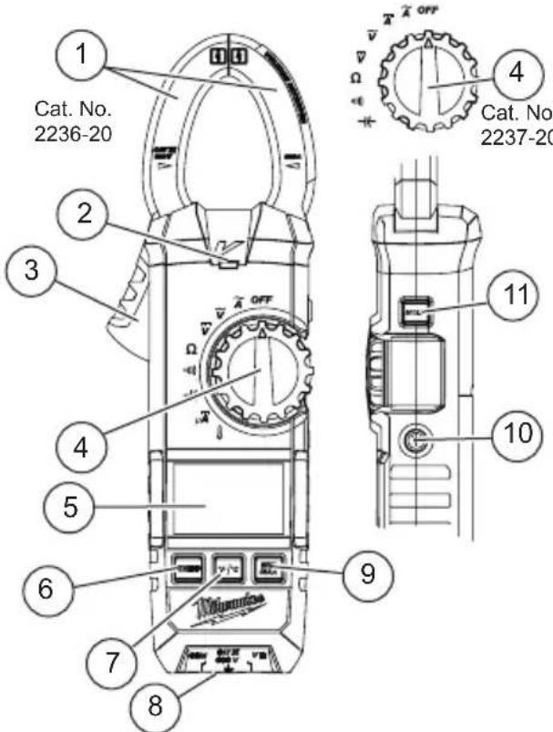
- Current sensing jaws
- NCVD indicator
- Jaw opening trigger
- Rotary Dial
- Display
-
Zero button
-
°F/°C button (2236-20) Hz button (2237-20)
- Terminal inputs
- Min/Max button
- Worklight LED
- Hold button
ASSEMBLY
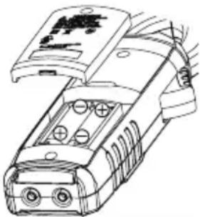
⚠ WARNING To avoid an electrical hazard, turn the Rotary Dial to OFF and disconnect the test leads before replacing batteries.
Loading/Changing the Batteries
Replace batteries when the Low Battery indicator is displayed.
- Turn Rotary Dial to OFF and disconnect the test leads.
- Unscrew and remove battery door.
- Insert two (2) AA batteries, according to the polarity marked in the battery compartment
- Close the battery door and tighten screw securely.
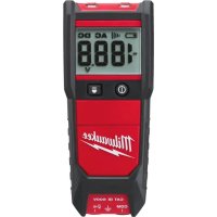
natural_image
Line drawing of a mobile phone casing with buttons and display panel (no text or symbols)OPERATION
⚠ WARNING Only use MILWAUKEE test leads with the MILWAUKEE Clamp Meters.
Inspect test leads before each use. Use clamp meter to run a continuity test.
Before Use
Confirm the Rotary Dial is set to the correct position, the instrument is set to the correct measurement mode, and the Data hold function is disabled. Otherwise, desired measurement cannot be made.
LCD Backlight
The LCD backlight will turn off after about 3 minutes of inactivity. Push any button or turn the rotary dial to turn the backlight on.
Making a Measurement
AC Current
ADANGER To avoid electrical shock:
ADANGER Never make measurement on a circuit in which voltage over AC600V exists. Clamp tips are designed not to short the circuit under test. If equipment under test has exposed conductive parts, however, extra precaution should be taken to minimize the possibility of shorting. Do not use with the Battery Cover removed. Disconnect the test leads from the instrument for current measurement.
- Set the Rotary Dial to position. AC mark is displayed.
- Press the jaw opening trigger to open the jaws and clamp them onto the conductor under test. The reading is displayed.
Cat. No. 2237-20 only: Pressing the "Hz" Key toggles the reading between AC Current and Hz.
NOTE: Hz Function requires 50A or more.
NOTE: Do not clamp over 2 or more wires at the same time. Irregular results will occur.
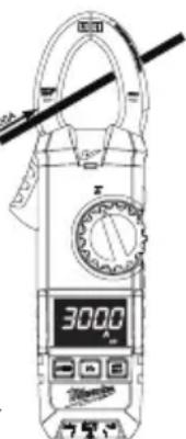
⚠️CAUTION Maximum conductor size is about 1.3" diameter. During measurement, keep the jaws fully closed to ensure accurate measurements.

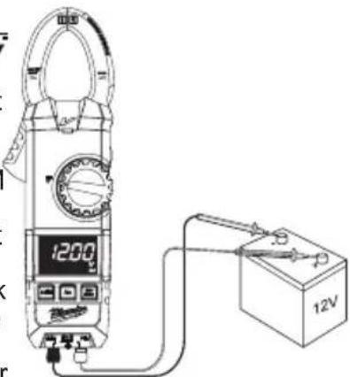
DC Current
(Cat. No. 2237-20 only)
⚠️DANGER To avoid electrical shock: Never make measurement on a circuit in which voltage over AC600V exists. Do not use with the Battery Cover removed.
- Set the Rotary Dial to Position. DC mark is displayed.
- With the jaws closed and without clamping them around a conductor, press the ZERO key to zero adjust the display.
- Press the jaw opening trigger to open the jaws and clamp them around the conductor under test. The reading is displayed.
NOTE: Do not clamp over 2 or more wires at the same time. Irregular results will occur.
- Set the Rotary Dial to an appropriate position according to current under test.
- Press the ZERO key again to release the ZERO function.
⚠️CAUTION When current flows from the display side to the underside of the meter, the polarity is positive; flow from underside to display side, the polarity is negative.

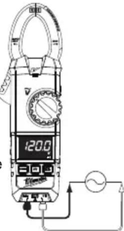
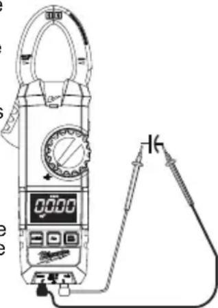
AC Voltage
A DANGER To avoid electrical shock:
Never make measurement on a circuit in which voltage over AC600V exists.
Do not use with the Battery Cover removed. Keep fingers away from jaws during measurements.
- Set the Rotary Dial to V position.
- Connect the red test lead to the VΩ terminal and the black test lead to the COM terminal.
- Connect the test leads to the circuit under test. The reading is displayed.
Cat. No. 2237-20 only: Pressing the Hz Key toggles the reading between AC Voltage and Hz. NOTE: Hz Function requires 70V or more.
CAUTION Readings of frequency may fluctuate or be influenced in noisy envi-
ronments.

DC Voltage
ADANGER To avoid electrical shock:
- DANCEIN Never make measurement on a circuit in which voltage over DC600V exists.
Do not use with the Battery Cover removed.
Keep fingers away from jaws during measurements.
-
Set the Rotary Dial to position.
-
Connect the red test lead to the VΩ terminal and the black test lead to the COM terminal.
-
Connect the red test lead to the positive (+) side and black test leads to the negative (-) side of the circuit under
test. The reading is displayed. A reversed connection is indicated as a negative value.
Resistance/Continuity/Capacitance Measurements
DANGER
To reduce the risk of electric shock for Resistance, Continuity, and
Capacitance measurements, never use the meter on an energized circuit. Make sure a capacitor is fully discharged before touching or attempting to make a measurement.
Do not use with the Battery Cover removed.

Resistance
-
Set the Rotary Dial to position.
-
Connect the red test lead to the VΩ terminal and the black test lead to the COM terminal.
Confirm "OL" is indicated on the display, and then short-circuit the tips of test leads to make the indication zero.
-
Connect the test leads to both ends of the resistor under test.
-
The reading is displayed.
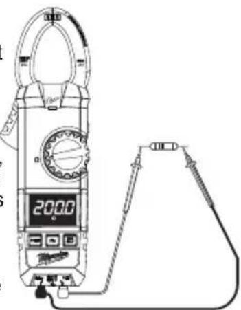
⚠️CAUTION After shorting the test leads, the displayed value may not be zero due to the resistance of test leads themselves.

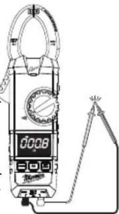
Continuity
-
Set the Rotary Dial to position.
-
Connect the red test lead to the VΩ terminal and the black test lead to the COM terminal.
Confirm "OL" is indicated on the display, and then short-circuit the tips of test leads to make the indication zero. A buzzer will sound.
- Connect the test leads to both ends of the conductor under test. If the resistance under test is 35 ± 10 or 25 or less, the buzzer will sound.

Capacitance
-
Set the Rotary Dial to position.
-
Connect the red test lead to the VΩ terminal and the black test lead to the COM terminal.
-
Discharge capacitor.
-
Connect the test leads to both ends of the capacitor under test.
-
The reading is displayed.

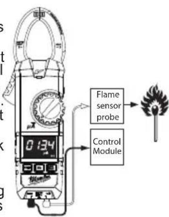
DC Current
(Cat. No. 2236-20 only)
To avoid electrical shock:
DANGER
Never make measurement on a ch voltage over AC600V exists. with the Battery Cover removed.
-
Set the Rotary Dial to A position. DC mark is displayed.
-
Connect the red test lead to the VΩ terminal and the black test lead to the COM terminal. Contact the red test lead to the flame sensor probe and the black test lead to the control module.
-
Turn on the heating unit. The reading is displayed.

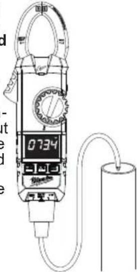
Temperature
(Cat. No. 2236-20 only)
WARNING
Never connect the Tempera-
ture Probe to an energized circuit.
-
Set the Rotary Dial to position.
-
Connect the K-type Temperature Probe to the input terminal. The positive (+) side of Probe should be connected to VΩ.
-
Place the probe sensor in the desired location.
-
The reading is displayed.
CAUTION
When the Rotary Dial is set to 🖼,
The room temperature should be displayed. If anything else is displayed, something may be wrong with the meter. Stop using the meter immediately.

Worklight LED ON/OFF
To turn the light on and off, press the button.
HOLD Key
Data Hold Function - Freezes the value on the display. Press the "HOLD" button to freeze the reading. The reading will be held regardless of subsequent variation in input. HOLD is displayed with the reading. To exit Data Hold mode, press the HOLD button again.
CAUTION
The Data Hold readings are released when the meter enters Sleep
Mode.
Sleep Mode
The clamp meter is automatically powered off in about 20 min after the last Rotary Dial or button operation. To reset, rotate the Rotary Dial to OFF. If the display is still blank when a new Rotary Dial setting is selected, replace the batteries.
The sleep mode is disabled when the MIN/MAX function is selected.
The clamp meter does use battery power in sleep mode. Be sure to switch the tool to OFF to conserve battery power.

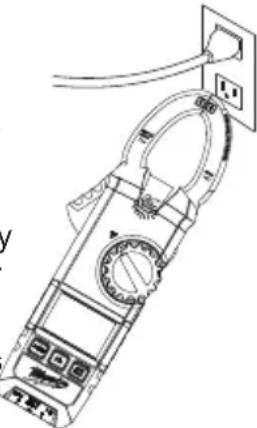
Non-Contact Voltage Detection (NCVD)
DANGER
The LED may not be displayed due to installation condition of electri-
cal circuit or equipment. Never touch the circuit under test to avoid possible danger even if the LED for NCVD is not displayed.
Check the functionality of LED on a well-known
power supply prior to measurement. When the LED doesn't light up, do not make measurement.
NCVD indication is affected by external voltage, and how the meter is held or placed.
When the meter is on in any function, the non-contact voltage detector will indicate with a Red LED on the display when an electric field exceeding 90V is detected. Place the edge of the jaw labeled "Voltage Detector" near the electric field.
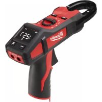
natural_image
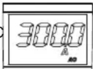
Technical line drawing of a handheld electrical meter with attached power outlet (no text or symbols)Over-flow indication
Any time the input exceeds the measuring range "OL" or "-OL" is displayed.
CAUTION
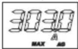
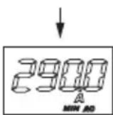
Clamp the jaws around the conductor under test and press the MIN/
MAX button after an appropriate range is selected by Auto-ranging function. ZERO and Hz keys are disabled while MIN/MAX Function is active.
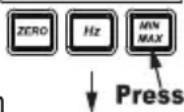
MIN/MAX Function
The MIN/MAX function can be used during measurements of AC or DC current, AC or DC voltage, Temperature (2236-20 only), uA DC (2236-20 only), and Resistance. The MIN/MAX function does not work in the Capacitance or Continuity measurements.
To measure the minimum or maximum of the function, set the dial to the appropriate dial position and then press the MIN/MAX button to capture the maximum reading. Press the MIN/MAX button again to capture the minimum reading.
Press the MIN/MAX button to toggle between minimum or maximum. The minimum or maximum reading is displayed and held until the MIN/MAX by holding in the MIN/MAX button for 2 Kchanging the Rotary Dial position.
CAUTION
Auto-Ranging and MIN/MAX button are disabled when ZERO function ZERO function operates only in AC Current and Capacitance.
ZERO Function
AC Current / DC Current
doesn't read ZERO while the Jaws are closed, press the ZERO Button to indicate ZERO before starting a measurement. In this case, the "ZERO" mark appears on the LCD to indicate the ZERO Function is activated.
Capacitance - Effective at 40nF Range only. Press the ZERO Button with the Test leads opened before measuring capacitances to indicate ZERO before starting a measurement.
When the LCD
MAINTENANCE
WARNING
To reduce the risk of injury, always remove the batteries from the tool before performing any maintenance. Never disassemble the tool. Contact a MILWAUKEE service facility for ALL repairs.
Maintaining Tool
Keep your tool in good repair by adopting a regular maintenance program. After one year, it is recommended to return the tool to a MILWAUKEE service -facility for calibration.
If the tool does not start or operate at full power with fully charged batteries, clean the contacts on the battery door. If the tool still does not work properly, return the tool to a MILWAUKEE service facility for repair.
WARNING
To reduce the risk of personal in-jury and damage, never immerse your tool, battery pack or charger in liquid or allow a liquid to flow inside them.
Cleaning
Clean dust and debris from vents. Keep handles clean, dry and free of oil or grease. Use only mild soap and a damp cloth to clean, since certain cleaning agents and solvents are harmful to plastics and other insulated parts. Some of these include gasoline, turpentine, lacquer thinner, paint thinner, chlorinated cleaning solvents, ammonia and household detergents containing ammonia. Never use flammable or combustible solvents around tools.
Repairs
For repairs, return the tool, battery pack and charger to the nearest service center.
ACCESSORIES
⚠ WARNING Use only recommended accessories. Others may be hazardous.
For a complete listing of accessories, go online to www.milwaukeeetool.com or contact a distributor.
SERVICE - UNITED STATES
1-800-SAWDUST (1.800.729.3878)
Monday-Friday, 7:00 AM - 6:30 PM CST
or visit www.milwaukeeetool.com
Contact Corporate After Sales Service Technical Support with technical, service/repair, or warranty questions.
Email: metproductsupport@milwaukeeetool.com
Become a Heavy Duty Club Member at www.milwaukeeetool.com to receive important notifications regarding your tool purchases.
SERVICE - CANADA
Milwaukee Tool (Canada) Ltd 1.800.268.4015
Monday-Friday, 7:00 AM - 4:30 PM CST or visit www.milwaukeetool.ca
FIVE YEAR TOOL LIMITED WARRANTY
MILWAUKEE Test & Measurement Product (including bare tool M12™ battery pack(s) and battery charger) is warranted to the original purchaser only to be free from defects in material and workmanship. Subject to certain exceptions, MILWAUKEE will repair or replace any part on this product which, after examination, is determined by MILWAUKEE to be defective in material or workmanship for a period of five (5) years* after the date of purchase. Return of the Test & Measurement tool to the nearest Milwaukee Electric Tool Corporation - factory Service Center, freight prepaid and insured is required. A copy of the proof of purchase should be included with the return product. This warranty does not apply to damage that MILWAUKEE determines to be from repairs made or attempted by anyone other than MILWAUKEE authorized personnel, misuse, alterations, abuse, normal wear and tear, lack of maintenance, or accidents.
* See separate & distinct CORDLESS BATTERY PACK LIMITED WARRANTY statement for the warranty period of the LITHIUM-ION battery pack that ships with Test & Measurement Product. *Alkaline battery that ships with Test & Measurement Product is separately warranted by the alkaline battery manufacturer.
*The warranty period for a Voltage Detector with Work Light – 2201 20, Voltage Detector with LED – 2202-20 or M12™ 2-Beam Plumb Laser – 2230 20 is one (1) year from the date of purchase.
Warranty Registration is not necessary to obtain the applicable warranty on MILWAUKEE product. The manufacturing date of the product will be used to determine the warranty period if no proof of purchase is provided at the time warranty service is requested.
ACCEPTANCE OF THE EXCLUSIVE REPAIR AND REPLACEMENT REMEDIES DESCRIBED HEREIN IS A CONDITION OF THE CONTRACT FOR THE PURCHASE OF EVERY MILWAUKEE PRODUCT. IF YOU DO NOT AGREE TO THIS CONDITION, YOU SHOULD NOT PURCHASE THE PRODUCT. IN NO EVENT SHALL MILWAUKEE BE LIABLE FOR ANY INCIDENTAL, SPECIAL, CONSEQUENTIAL OR PUNITIVE DAMAGES, OR FOR ANY COSTS, ATTORNEY FEES, EXPENSES, LOSSES OR DELAYS ALLEGED TO BE AS A CONSEQUENCE OF ANY DAMAGE TO, FAILURE OF, OR DEFECT IN ANY PRODUCT INCLUDING, BUT NOT LIMITED TO, ANY CLAIMS FOR LOSS OF PROFITS. SOME STATES DO NOT ALLOW THE EXCLUSION OR LIMITATION OF INCIDENTAL OR CONSEQUENTIAL DAMAGES, SO THE ABOVE LIMITATION OR EXCLUSION MAY NOT APPLY TO YOU. THIS WARRANTY IS EXCLUSIVE AND IN LIEU OF ALL OTHER WARRANTIES, WRITTEN OR ORAL. TO THE EXTENT PERMITTED BY LAW, MILWAUKEE DISCLAIMS ANY IMPLIED WARRANTIES, INCLUDING WITHOUT LIMITATION ANY IMPLIED WARRANTY OF MERCHANTABILITY OR FITNESS FOR A PARTICULAR USE OR PURPOSE; TO THE EXTENT SUCH DISCLAIMER IS NOT PERMITTED BY LAW, SUCH IMPLIED WARRANTIES ARE LIMITED TO THE DURATION OF THE APPLICABLE EXPRESS WARRANTY AS DESCRIBED ABOVE. SOME STATES DO NOT ALLOW LIMITATIONS ON HOW LONG AN IMPLIED WARRANTY LASTS, SO THE ABOVE LIMITATION MAY NOT APPLY TO YOU, THIS WARRANTY GIVES YOU SPECIFIC LEGAL RIGHTS, AND YOU MAY ALSO HAVE OTHER RIGHTS WHICH VARY FROM STATE TO STATE.
This warranty applies to product sold in the U.S.A. and Canada only.
LIMITED WARRANTY - MEXICO, CENTRAL AMERICA & CARIBBEAN
TECHTRONIC INDUSTRIES' warranty is for 5 years since the original purchase date.
This warranty card covers any defect in material and workmanship on this Product.
To make this warranty valid, present this warranty card, sealed/ stamped by the distributor or store where you purchased the product, to the Authorized Service Center (ASC). Or, if this card has not been sealed/stamped, present the original proof of purchase to the ASC. Call toll-free1 01 (800) 030-7777 to find the nearest ASC, for service, parts, accessories or components.
Procedure to make this warranty valid
Take the product to the ASC, along with the warranty card sealed/ stamped by the distributor or store where you purchased the product, and any faulty piece or component will be replaced without cost for you. We will cover all freight costs relative with this warranty process.
Exceptions
This warranty is not valid in the following situations
a) When the product is used in a different manner from the end-user guide or instruction manual.
b) When the conditions of use are not normal.
c) When the product was modified or repaired by people not authorized by TECHTRONIC INDUSTRIES.
Note: If cord set is damaged, it should be replaced by an Authorized Service Center to avoid electric risks.
SERVICE AND ATTENTION CENTER
Call to 01 (800) 030-7777
IMPORTED AND COMMERCIALIZED BY
TECHTRONIC INDUSTRIES MEXICO, SA DE CV
Av President Masarik #29 piso 7, Col. Polanco V Sección
CP 11560, Deleg. Miguel Hidalgo, CDMX
Model:
Date of Purchase:
Distributor or Store Stamp:
RÈGLES IMPORTANTES DE SÉCURITÉ
AVERTISSEMENT
LIRE TOUS LES AVERTISSEMENTS ET TOUTES LES INSTRUCTIONS.
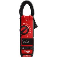
natural_image
Technical line drawing of a handheld electronic device with visible circuitry and wiring (no text or symbols)UTILISATION
AVERTISSEMENT
ATTENTION
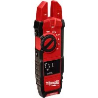
natural_image
Line drawing of a handheld electrical clamp with power outlet (no text or symbols)Milwaukee Tool (Canada) Ltd 1.800.268.4015
Monday-Friday, 7:00 AM - 4:30 PM CST www.milwaukeeetool.ca
GARANTIE LIMITÉE - AUX ÉTATS-UNIS ET AU CANADA
natural_image
Technical line drawing of a handheld electronic device with multiple ports and wiring (no text or symbols)FUNCIONAMIENTO
ADVERTENCIA
natural_image
Line drawing of a digital clamp meter with a digital display and connected tubing (no text or symbols)PRECAUCIÓN
natural_image
Technical line drawing of a handheld device with attached power outlet (no text or symbols)MANTENIMIENTO
ADVERTENCIA
Lunes a Viernes (9am a 6pm)
13135 West Lisbon Road
Brookfield, WI 53005 USA
- IMPORTANT SAFETY INSTRUCTIONS
- WARNING
- READ ALL SAFETY WARNINGS AND INSTRUCTIONS.
- DANGER
- CAUTION
- GENERAL SPECIFICATIONS
- SYMBOLOGY
- FUNCTIONAL DESCRIPTION
- ASSEMBLY
- ⚠ WARNING To avoid an electrical hazard, turn the Rotary Dial to OFF and disconnect the test leads before replacing batteries.
- Loading/Changing the Batteries
- OPERATION
- ⚠ WARNING Only use MILWAUKEE test leads with the MILWAUKEE Clamp Meters.
- Before Use
- LCD Backlight
- Making a Measurement
- A AC Current
- ADANGER To avoid electrical shock:
- DC Current
- ⚠️DANGER To avoid electrical shock: Never make measurement on a circuit in which voltage over AC600V exists. Do not use with the Battery Cover removed.
- ⚠️CAUTION When current flows from the display side to the underside of the meter, the polarity is positive; flow from underside to display side, the polarity is negative.
- AC Voltage
- A DANGER To avoid electrical shock:
- CAUTION Readings of frequency may fluctuate or be influenced in noisy envi-
- DC Voltage
- Resistance/Continuity/Capacitance Measurements
- Resistance
- ⚠️CAUTION After shorting the test leads, the displayed value may not be zero due to the resistance of test leads themselves.
- Continuity
- Capacitance
- Temperature
- Worklight LED ON/OFF
- HOLD Key
- The Data Hold readings are released when the meter enters Sleep
- Mode.
- Sleep Mode
- Non-Contact Voltage Detection (NCVD)
- Over-flow indication
- MIN/MAX Function
- Auto-Ranging and MIN/MAX button are disabled when ZERO function ZERO function operates only in AC Current and Capacitance.
- ZERO Function
- MAINTENANCE
- Maintaining Tool
- Cleaning
- Repairs
- ACCESSORIES
- ⚠ WARNING Use only recommended accessories. Others may be hazardous.
- SERVICE - UNITED STATES
- 1-800-SAWDUST (1.800.729.3878)
- SERVICE - CANADA
- Milwaukee Tool (Canada) Ltd 1.800.268.4015
- FIVE YEAR TOOL LIMITED WARRANTY
- LIMITED WARRANTY - MEXICO, CENTRAL AMERICA & CARIBBEAN
- Procedure to make this warranty valid
- Exceptions
- RÈGLES IMPORTANTES DE SÉCURITÉ
- AVERTISSEMENT
- LIRE TOUS LES AVERTISSEMENTS ET TOUTES LES INSTRUCTIONS.
- UTILISATION
- ATTENTION
- GARANTIE LIMITÉE - AUX ÉTATS-UNIS ET AU CANADA
- FUNCIONAMIENTO
- ADVERTENCIA
- PRECAUCIÓN
- MANTENIMIENTO
Brand : MILWAUKEE
Model : 223720
Category : Multimeter